Table of Contents
Advertisement
Quick Links
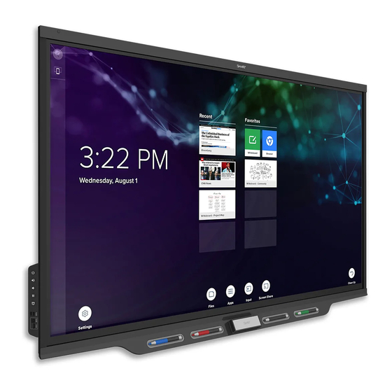
SMART Board® 7000 and
7000 Pro series
interactive displays
INSTALLATION AND MAINTENANCE GUIDE
SBID-7275-V2
|
SBID-7286-V2
SBID-7075-V2
|
SBID-7086-V2
SBID-7375
|
SBID-7386
|
SBID-7275
SBID-7375P
|
SBID-7386P
|
SBID-7275P
ID7075-2
|
ID7086-2
|
ID7075-1
Was this document helpful?
smarttech.com/docfeedback/171164
|
SBID-7275P-V2
|
SBID-7286P-V2
|
SBID-7075P-V2
|
SBID-7086P-V2
|
SBID-7286
|
SBID-7075
|
SBID-7286P
|
SBID-7075P
|
ID7086-1
|
SBID-7086
|
SBID-7086P
Advertisement
Table of Contents
Troubleshooting

Subscribe to Our Youtube Channel
Related Manuals for Smart Technologies Board 7000 Series


Summary of Contents for Smart Technologies Board 7000 Series
- Page 1 SMART Board® 7000 and 7000 Pro series interactive displays INSTALLATION AND MAINTENANCE GUIDE SBID-7275-V2 SBID-7286-V2 SBID-7275P-V2 SBID-7286P-V2 SBID-7075-V2 SBID-7086-V2 SBID-7075P-V2 SBID-7086P-V2 SBID-7375 SBID-7386 SBID-7275 SBID-7286 SBID-7075 SBID-7086 SBID-7375P SBID-7386P SBID-7275P SBID-7286P SBID-7075P SBID-7086P ID7075-2 ID7086-2 ID7075-1 ID7086-1 Was this document helpful? smarttech.com/docfeedback/171164...
- Page 2 Learn more This guide and other resources for SMART Board 7000 and 7000 Pro series interactive displays are available in the Support section of the SMART website (smarttech.com/support). Scan this QR code to view these resources on your mobile device. Licenses The terms HDMI and HDMI High-Definition Multimedia Interface, and the HDMI logo are trademarks or registered trademarks of HDMI Licensing LLC in the United States and other countries.
-
Page 3: Important Information
Important information Objects fall into the display WARNING The display is dropped Failure to follow the installation instructions included with Structural damage, such as cracking, occurs the display could result in injury and product damage The display behaves unexpectedly when you which may not be covered by the warranty. - Page 4 Important information IMPORTANT Model Power requirements The following are the normal operating power SBID-7275P 100V to 240V AC, 50 Hz to 60 requirements for the display: Hz, 141 W Model Power requirements SBID-7286P 100V to 240V AC, 50 Hz to 60 Hz, 165 W SBID-7000-V2 models SBID-7375P...
- Page 5 47 CFR § 2.1077 Compliance Information Unique Identifier: SBID-7075, ID7075-1, ID7075-2, ID7086- 1, ID7086-2 Responsible Party – U.S. Contact Information SMART Technologies Inc. 1505 Westlake Ave N, Suite 700 Seattle, WA 98109 compliance@smarttech.com This device complies with Part 15 of the FCC Rules. Operation is subject to the following two conditions: 1.
- Page 6 Important information Innovation, Science and Economic (iii) le gain maximal d’antenne permis (pour les dispositifs utilisant la bande 5 725-5 825 MHz) doit se conformer à la limite Development Canada statement de p.i.r.e. spécifiée pour l’exploitation point à point et non point à This device complies with RSS-247 of the Innovation, Science and point, selon le cas.
- Page 7 Important information EU declaration of conformity United Arab Emirates – TRA registration details Hereby, SMART Technologies ULC declares that the radio equipment type Interactive Display SBID-7075, SBID-7075P, Pen – Regulatory models SBID-7000-Pen and SBID-7000P-PEN SBID-7086, SBID-7086P, ID7075-1, ID7086-1, SBID-7075-V2, SBID-7075P-V2, SBID-7086-V2, SBID-7086P-V2, ID7075-2, ID7086-2 and the interactive pen SBID-7000-PEN, SBID-7000P- PEN are in compliance with Directive 2014/53/EU.
-
Page 8: Table Of Contents
Contents Important information Chapter 1: Welcome About this guide Identifying your specific model Features Components Accessories More information Chapter 2: Installing the display Moving the display to the installation site Installing the display on a wall Installing the display on a stand Chapter 3: Connecting power and devices Connecting power Connecting to a network... - Page 9 Contents Removing and transporting the display Updating system software Chapter 6: Troubleshooting Resolving issues with power Resolving issues with the occupancy sensors Resolving issues with video Resolving issues with image quality Resolving issues with audio Resolving issues with touch and digital ink Resolving issues with the iQ experience Resolving issues with the Intel Compute Card Resolving issues with the SMART OPS PC module...
-
Page 10: Chapter 1: Welcome
Chapter 1 Welcome About this guide Identifying your specific model Identifying your SMART Board 7000 or 7000 Pro series interactive display model Identifying your appliance model Features Components Screen IR and occupancy sensors Home button Pens and eraser Convenience panel Accessory slot Internal speakers Accessories SBA-100 projection audio system... -
Page 11: Identifying Your Specific Model
Chapter 1 Welcome In addition, this guide includes information on the display’s settings and remote management support. This guide is intended for those who install and maintain displays in their organizations. Other documentation and resources are available for those who use displays (see More information on page 19). Identifying your specific model SMART offers several different models of the SMART Board 7000 and 7000 Pro series interactive display and appliance. -
Page 12: Identifying Your Appliance Model
Chapter 1 Welcome Model Location of Frame style Screen size Embedded convenience and Windows 10 connector panels experience SBID-7086P Right side Black 86" White SBID-7275P Right side Black 75" White SBID-7286P Right side Black 86" White SBID-7375P Right side Black 75"... -
Page 13: Features
Chapter 1 Welcome Features The SMART Board 7000 or 7000 Pro series interactive display is the hub of your classroom or meeting room. PC-free embedded computing provides one-touch access to collaborative tools, including a whiteboard, wireless screen sharing and a web browser. There’s no need for wires, cables or manual software and firmware updates. -
Page 14: Components
Chapter 1 Welcome Components The display consists of the following components: Name More information Pictured Screen Page 15 IR and occupancy sensors Page 16 Home button Page 17 Eraser Page 17 Pen (×4) Page 17 Convenience panel Page 17 Accessory slot Page 17 Side connector panel Page 38 Not pictured Bottom connector panel Page 38... -
Page 15: Screen
Chapter 1 Welcome Screen The following are the dimensions of the screen: Model Diagonal Width Height SBID-7000-V2 models SBID-7075-V2 75" 65" (165.2 cm) 38 5/8" (93 cm) SBID-7086-V2 86" 74 7/8" (190.3 cm) 42" (107 cm) SBID-7275-V2 75" 65" (165.2 cm) 38 5/8"... -
Page 16: Ir And Occupancy Sensors
Chapter 1 Welcome IR and occupancy sensors SBID-7000-V2 models have an IR sensor (for an optional remote control) in the top-left corner of the frame and an occupancy sensor in the top-right corner. SBID-7000 models have occupancy sensors in the top-left and top-right corners of the frame. The occupancy sensors can detect people up to 16' (5 m) away when the display is in Standby mode. -
Page 17: Home Button
Chapter 1 Welcome Home button Tap the Home button to open the Home screen on models with the iQ experience. From the Home screen, you can open the iQ experience apps as well as the settings. Pens and eraser The display comes with black, red, blue and green pens. Each pen has an attached eraser and an indicator light. -
Page 18: Accessories
Chapter 1 Welcome Internal speakers The display includes two 10 W integrated speakers. You can also connect an external audio system (see Connecting an external audio system on page 36). Accessories Accessories for the display include: SBA-100 projection audio system SMART Audio 400 classroom amplification system Stands USB extenders Embedded Windows 10 experience hardware... -
Page 19: More Information
Chapter 1 Welcome Stands If you want to move the display from place to place, you can install it on a SMART mobile stand. Alternatively, if you are installing the display on a wall that cannot support the display’s full weight, you can install the display on a SMART floor stand. -
Page 20: Chapter 2: Installing The Display
Chapter 2 Installing the display Moving the display to the installation site Using transportation aides Accommodating doorways, hallways and elevators Dealing with cracked, chipped or shattered glass Saving the original packaging Installing the display on a wall Choosing a location Choosing a height Assessing the wall Selecting mounting hardware... -
Page 21: Using Transportation Aides
Chapter 2 Installing the display IMPORTANT Move the display at your own risk. SMART cannot accept liability for damages or injury that occur during the display’s transportation. When moving the display Follow local safety regulations and standards. Pack the display in its original packaging, including the pallet. Move the display so that its top frame faces up. -
Page 22: Installing The Display On A Wall
Chapter 2 Installing the display of the display. These foam pieces protect the display if you need to set it down during transportation. You might also need to rotate the display so that its top frame faces to the side. You can do this during transportation, but when you install the display, it must be in landscape orientation (with the top frame facing up). -
Page 23: Choosing A Location
Chapter 2 Installing the display Choosing a location A display is typically installed at the room’s focal point, such as at the front of a classroom or meeting space. Selecting an appropriate location for the display is crucial for ensuring the best possible experience with the product. - Page 24 Chapter 2 Installing the display Factor Considerations Visibility The display’s screen is clearly visible to all users in the room. SMART recommends users sit within a 178° viewing area: NOTE The viewing area depends on the display’s resolution and a variety of other factors.
-
Page 25: Choosing A Height
Chapter 2 Installing the display Choosing a height Consider the general height of the user community when you choose the height for the display. SMART recommends that you mount the display so that its top is 6' 5" (1.9 m) from the floor. NOTE If participants will be sitting at a steep angle (such as in a lecture hall), you may have to adjust the installation height or angle. -
Page 26: Mounting The Display
Chapter 2 Installing the display Contact your authorized SMART reseller (smarttech.com/where) for information on SMART’s mounting options. If you choose a third-party option rather than one of SMART’s mounting options, be sure the wall mount can accommodate the display’s dimensions and support the display’s weight as well as the weight of any attached accessories. - Page 27 Chapter 2 Installing the display Use M8 bolts (not included) to fasten the wall bracket. Bolt length 12 mm + x mm < M8 < 45 mm + x mm where x is the combined thickness of the wall bracket and washer 97.36–177.01 in-lb.
-
Page 28: Mounting Multiple Displays
Chapter 2 Installing the display Mounting multiple displays If you mount multiple displays side by side, you can connect them with RS-232 cables to turn on, turn off and otherwise operate all of the displays from the first display’s convenience panel: When connecting SBID-7000-V2 models, the leftmost display (when viewed from the front) is the first display. -
Page 29: Installing The Display On A Stand
Chapter 2 Installing the display NOTE For more information on using RS-232 cables for remote management, see Appendix B: Remotely managing the display on page 70. Installing the display on a stand If you want to move the display from place to place or if it’s not possible to install the display on a wall, you can install it on a stand. -
Page 30: Chapter 3: Connecting Power And Devices
Chapter 3 Connecting power and devices Connecting power Connecting to a network Connecting the Intel Compute Card or SMART OPS PC module Connecting cables for room computers, guest laptops and other input sources Connecting an external display Connecting an external audio system Connecting room control systems SBID-7000-V2 connectors reference SBID-7000 connectors reference... -
Page 31: Connecting Power
Chapter 3 Connecting power and devices Connecting power Connect the supplied power cable from the AC power inlet on the bottom of the display to a power outlet. SBID-7000-V2 SBID-7000 NOTE Refer to the display’s specifications for power requirements and power consumption information (see More information on page 19). -
Page 32: Connecting The Intel Compute Card Or Smart Ops Pc Module
Chapter 3 Connecting power and devices IMPORTANT Do not use the RJ45 jack on the appliance or the SMART OPS PC module to connect to a network. TIPS If you’re using one of the display’s RJ45 jacks to connect to a network, you can connect the other RJ45 jack to a computer to provide network access for the computer. -
Page 33: Connecting Cables For Room Computers, Guest Laptops And Other Input Sources
Chapter 3 Connecting power and devices You can connect peripherals, such as a keyboard or mouse, to the embedded Windows 10 experience using the USB receptacles on the AM50 appliance or the OPS PC module. Connecting cables for room computers, guest laptops and other input sources You can connect cables to the display so that users can connect and use room computers, guest laptops or other devices, such as Blu-ray™... - Page 34 Chapter 3 Connecting power and devices Input Video/audio Touch HDMI 3 HDMI 2.0 USB 3.0 VGA (video) USB 3.0 Stereo 3.5 mm (audio) There is limited space between the side connector panel and the back of the convenience panel. When making connections within the limited space, use flexible, high-quality cables that do not include a larger strain relief feature.
- Page 35 Chapter 3 Connecting power and devices IMPORTANT Do not connect computers or other devices to the connectors on the appliance. SMART Board 7000 series and 7000 Pro series interactive displays do not support the use of these connectors. SMART recommends the following varieties of cable: Cable type Maximum length Recommendation...
-
Page 36: Connecting An External Display
Chapter 3 Connecting power and devices Connecting an external display You can connect an external display to an SBID-7000-V2 model using the HDMI 2.0 out connector on the side connector panel (pictured). The external display will show the same image as the SBID-7000-V2 model. This is useful when you’re using the SBID-7000-V2 model in an auditorium or other large space where it would be beneficial to have a second display. -
Page 37: Connecting Room Control Systems
Chapter 3 Connecting power and devices You can connect an external audio system to the display using the stereo 3.5 mm out connector (pictured). Alternatively, you can connect an external audio system directly to a room computer. SBID-7000-V2 SBID-7000 In addition to the stereo 3.5 mm out connector, the display provides a Sony/Philips Digital Interface (S/PDIF) out connector. -
Page 38: Sbid-7000-V2 Connectors Reference
Chapter 3 Connecting power and devices NOTE Displays are not compatible with centralized remote control systems, such as a universal remote control. SBID-7000-V2 connectors reference The following diagrams and table present the connectors on SBID-7000-V2 models’ connector panels: Side connector panel Bottom connector panel Connector Connects to... - Page 39 Chapter 3 Connecting power and devices Connector Connects to Notes Stereo 3.5 mm out External audio system See page 36 and Analog audio cables and connectors. Stereo 3.5 mm in VGA input (audio) See page 33 and Analog audio cables and connectors. VGA in VGA input (video) See page 33 and...
-
Page 40: Sbid-7000 Connectors Reference
Chapter 3 Connecting power and devices SBID-7000 connectors reference The following diagram and table present the connectors on SBID-7000 models’ connector panels: Connector Connects to Notes Stereo 3.5 mm out External audio system See page 36 and Analog audio cables and connectors. -
Page 41: Appliance Reference
Chapter 3 Connecting power and devices Connector Connects to Notes USB Type-A [N/A] This connector is a service port. RJ45 (×2) Network See page 31 and Ethernet (network) cables and connectors. The following diagram and table present the connectors on SBID-7000 models’ convenience panels: Connector Connects to Notes... - Page 42 Chapter 3 Connecting power and devices Connector Connects to Notes RJ45 Network Do not use this jack. Use the jacks on the display instead. See page 31. USB Type-A (×2) Supported peripherals [N/A] HDMI out External monitor This receptacle is HDCP-encrypted HDMI.
- Page 43 Chapter 3 Connecting power and devices Connector Connects to Notes Lock and Eject LEDs [N/A] The Lock LED lights when the iQ appliance (AM50) shouldn’t be removed from the display. The Eject LED lights when it is safe to remove the iQ appliance (AM50) from the display.
-
Page 44: Smart Ops Pc Module Reference
Chapter 3 Connecting power and devices SMART OPS PC module reference The following diagram and table present the connectors on the optional SMART OPS PC module: Connector Connects to Notes USB Type-C Supported USB drives, USB cables and connectors. peripherals, and other devices USB 2.0 Type-A (×2) Supported USB drives,... -
Page 45: Other Connectors
Chapter 3 Connecting power and devices Other connectors There are additional connectors on the bottom of the display (see Mounting multiple displays on page 28 and Appendix B: Remotely managing the display on page 70). smarttech.com/kb/171164... -
Page 46: Chapter 4: Turning On The Display For The First Time
Chapter 4 Turning on the display for the first time Turn on the display after mounting it and connecting power and devices. To turn on and set up the display for the first time 1. Flick the switch beside the AC power inlet to the ON (I) position. SBID-7000-V2 SBID-7000 2. - Page 47 Chapter 4 Turning on the display for the first time 9. Select the list of applications that will appear in the launcher, and then tap Next. For more information about the apps, see the SMART Board 7000 and 7000 Pro series interactive displays user guide (smarttech.com/kb/171163) 10.
-
Page 48: Chapter 5: Maintaining The Display
Chapter 5 Maintaining the display Checking the display installation Cleaning the screen Maintaining ventilation Preventing condensation Replacing the pens and eraser Turning the display off and back on Resetting the display Removing and transporting the display Updating system software Applying an automatic system software update manually Updating system software manually With proper maintenance, the display will provide years of use. -
Page 49: Maintaining Ventilation
Chapter 5 Maintaining the display Do not rub the screen with dense or rough material. Do not apply pressure to the screen. Do not use cleaning solutions or glass cleaners on the screen, because they can deteriorate or discolor the screen. To clean the screen 1. -
Page 50: Replacing The Pens And Eraser
Chapter 5 Maintaining the display If there is enough moisture between the layers to cause the moisture to drip and run, remove power immediately and contact SMART Support if the display is still under warranty. Replacing the pens and eraser To prevent damage to the display’s anti-glare coating, replace a pen if its nib or eraser pad become worn. -
Page 51: Resetting The Display
Chapter 5 Maintaining the display Resetting the display You can reset the display and the iQ appliance using the convenience panel. To reset the display Press and hold the Power button on the convenience panel for 10 seconds. The display and iQ appliance reset. Removing and transporting the display If the display is wall mounted, you might need to remove it from its current location and transport it to another location on occasion. -
Page 52: Updating System Software
Chapter 5 Maintaining the display 6. Lift the display from its mounting location. WARNING Do not place the display on a sloping or unstable cart, stand or table. The display could fall, resulting in injury and severe product damage. CAUTION Do not leave the display face up, face down or upside down for an extended period. -
Page 53: Updating System Software Manually
Chapter 5 Maintaining the display 3. Under Check for Updates Now, tap Apply Update Now. The display turns off and then turns back on. The display then applies the update. If there is an update for the pen firmware, the pen’s indicator light will flash green or amber. Leave the pen in the tray until the pen’s light is a solid color. - Page 54 Chapter 6 Troubleshooting Resolving issues with power Resolving issues with the occupancy sensors Resolving issues with video Resolving issues with image quality Resolving issues with audio Resolving issues with touch and digital ink Resolving issues with the iQ experience Resolving issues with the Intel Compute Card Resolving issues with the SMART OPS PC module Resolving issues with software Referring to the SMART knowledge base for additional troubleshooting information...
-
Page 55: Chapter 6 Troubleshooting
Chapter 6 Troubleshooting Resolving issues with power Issue Solutions The display doesn’t turn on and its Make sure the power cable is securely fastened to the power outlet and the display. power light isn’t lit. NOTE If the power cable is connected to a power bar, make sure the power bar is securely fastened to the power outlet and turned on. -
Page 56: Resolving Issues With Video
Chapter 6 Troubleshooting Resolving issues with video Issue Solutions You’re experiencing the following or Make sure any connected computers are on and not in Standby mode. similar issues with video: If the display has an appliance, make sure the appliance is securely installed in the accessory slot and its power light is on. -
Page 57: Resolving Issues With Audio
Chapter 6 Troubleshooting Issue Solutions Colors don’t appear correctly. Be aware that if two or more displays are mounted side-by-side, there could be minor differences in colors across the displays. This issue is not unique to SMART products. If you’re using a VGA video input, use a different cable or connect a different source to see if the issue is with the cable or input source. -
Page 58: Resolving Issues With Touch And Digital Ink
System Information and ensure there are no error messages in the display’s row. You’re experiencing issues with one Use only SMART Board 7000 series or 7000 Pro series interactive display pens with the or more of the display’s pens. display. Pens from other interactive displays aren’t compatible. -
Page 59: Resolving Issues With The Iq Experience
Chapter 6 Troubleshooting Resolving issues with the iQ experience For information on resolving issues with the iQ experience, including the Whiteboard, SMART Notebook® Player, Browser, Input and Screen Share apps, see Troubleshooting iQ system software. Resolving issues with the Intel Compute Card For information on resolving issues with the Intel Compute Card, including the drivers, see Troubleshooting Windows 10 on Intel Compute... -
Page 60: Referring To The Smart Knowledge Base For Additional Troubleshooting Information
Chapter 6 Troubleshooting Troubleshooting SMART TeamWorks™ Troubleshooting SMART Ink 5 Troubleshooting SMART Product Drivers 12 Referring to the SMART knowledge base for additional troubleshooting information Refer to the SMART knowledge base for additional troubleshooting information: community.smarttech.com/s/topic/0TO0P00000010RIWAY/7000-series Contacting your reseller for additional support If an issue you’re experiencing with the display persists or isn’t covered in this chapter or the knowledge base, contact your authorized SMART reseller (smarttech.com/where) for support. -
Page 61: Appendix A: Adjusting Settings
Appendix A Adjusting settings Network settings Personalization Application settings System settings You can access settings using the icon on the Home screen. NOTES Settings can apply to a user or to the entire system. User-level settings change depending on the user who is signed in. -
Page 62: Network Settings Personalization
Appendix A Adjusting settings Option Values Function Notes User or system setting SMART iQ Ethernet [N/A] Options available when an Ethernet [N/A] System Advanced options cable is connected Static IP (Use DHCP) Enables or disables DHCP to assign [N/A] User the display an IP address. Enables or disables a proxy server for [N/A] User... -
Page 63: Application Settings
Appendix A Adjusting settings Option Values Function Notes User or system setting [Wallpapers] Select the wallpaper that 1920 × 1080 images User Wallpaper appears in the work best background. The display supports .png and .jpg file formats Changing the display’s wallpaper. - Page 64 Appendix A Adjusting settings Option Values Function Notes User or system setting Enables or disables the Capture If this option is off, the User Saving Whiteboards function in the SMART kapp app. QR code is not visible. The SMART kapp app cannot connect to the display and your mobile device cannot save...
-
Page 65: System Settings
Appendix A Adjusting settings Option Values Function Notes User or system setting When enabled, the display SMART recommends System Miracast Connection disconnects from the network when enabling this setting Handling a device shares its screen using for areas with high Miracast. network saturation or busy networks. - Page 66 Appendix A Adjusting settings Option Values Function Notes User or system setting Disabled Sets the number of minutes of The default is 60 System Sleep inactivity before the display goes to minutes. 1 minute sleep. 5 minutes 30 minutes 60 minutes 90 minutes HDMI Output Default resolution...
- Page 67 Appendix A Adjusting settings Option Values Function Notes User or system setting Date & Time Sets the display’s date and time Configure the System Automatic Date & Time automatically. network to allow Network Time Protocol (NTP) requests to internet time servers.
- Page 68 Appendix A Adjusting settings Option Values Function Notes User or system setting Clean up Disabled Sets how often the display cleans up. [N/A] User Clean Up Policy Manually reset with the Clean Up button in the launcher 1 hour 2 hours 3 hours 1 day [N/A]...
- Page 69 Appendix A Adjusting settings Option Values Function Notes User or system setting Remote Management [N/A] Configure the display’s connection This option is only System Launch Remote settings with the Radix Viso server. enabled when Management Settings Remote Management is enabled. Enables or disables Remote [N/A] User...
-
Page 70: Appendix B: Remotely Managing The Display
Appendix B Remotely managing the display Connecting multiple displays Configuring the computer’s serial interface settings Power states Commands and responses Power state commands Input commands Brightness commands Freeze commands Screen shade commands Volume commands Mute commands Firmware version commands Serial number commands Part number commands Resolving issues with remote management You can connect an RS-232 cable from the computer’s serial output to the RS-232 IN connector on the... -
Page 71: Connecting Multiple Displays
Appendix B Remotely managing the display SBID-7000-V2 SBID-7000 IMPORTANT Use only a standard RS-232 cable. Do not use a null modem cable. Null modem cables typically have ends of the same type. Connecting multiple displays You can connect up to ten displays to a room control system by connecting a RS-232 cable from the computer’s serial output to the first display’s RS-232 IN connector and then connecting another RS-232 cable from that display’s RS-232 OUT connector to the next display’s RS-232 IN connector. - Page 72 Appendix B Remotely managing the display NOTES When connecting SBID-7000-V2 models, the leftmost display (when viewed from the front) is the first display in the chain, the display to the right of that display is the second display in the chain, and so on.
-
Page 73: Configuring The Computer's Serial Interface Settings
Appendix B Remotely managing the display When you connect displays in this manner, they behave as a single unit (see Mounting multiple displays on page 28). With the exception of the get input, set input, and get fwver, all remote management commands apply to all connected displays. Configuring the computer’s serial interface settings Configure the computer’s serial interface before sending commands to the display. -
Page 74: Commands And Responses
Appendix B Remotely managing the display Power state Description READY The screen is off, but the display is ready to turn on when the following occurs: A user presses the Power button on the convenience panel. A user picks up a pen or the eraser. You send the set powerstate=on command. - Page 75 Appendix B Remotely managing the display In the example below, the user used =-50 instead of -50. INCORRECT >set volume=-50 invalid cmd: setvolume=-50 > NOTES Use ASCII formatted commands. Commands aren’t case-sensitive and extra spacing is ignored. You can use the BACKSPACE key when typing commands. Review each entry carefully before you press ENTER.
- Page 76 Appendix B Remotely managing the display To increase or decrease the value of a setting Use the set command to increase or decrease the value by a designated number. This example increases the volume by 5: >set volume+5 volume=70 > This example decreases the volume by 15: >set volume-15 volume=55...
-
Page 77: Power State Commands
Appendix B Remotely managing the display Power state commands Get command Set command Response get powerstate set powerstate[Value] powerstate=[Value] Where [Value] is one of the following: Where [Value] is one of the following: =ready ready =standby standby =powersave powersave updateon NOTE updateready If the display is in UPDATEON or... -
Page 78: Brightness Commands
Appendix B Remotely managing the display Get command Set command Response If multiple displays are connected [Display],@ get input [Display],@ set input[Value] @,[Display] input=[Value] Where Where Where [Display] is the display’s label (A, B, and so on). [Display] is the display’s label (A, B, [Display] is the display’s label (A, B, and so on). -
Page 79: Screen Shade Commands
Appendix B Remotely managing the display Screen shade commands Get command Set command Response get screenshade set screenshade[Value] screenshade=[Value] Where [Value] is one of the following: Where [Value] is one of the following: =off NOTE Screen shade commands are available only for SMART Board 7000-V2 models. Volume commands Get command Set command... -
Page 80: Serial Number Commands
Appendix B Remotely managing the display Get command Response If multiple displays are connected [Display],@ get fwversion @,[Display] fwverversion=[Value] Where Where [Display] is the display’s label (A, B, and so on). [Display] is the display’s label (A, B, and so on). [Value] is the firmware version. - Page 81 Appendix B Remotely managing the display Issue Solutions You’re experiencing other issues with See Referring to the SMART knowledge base for additional troubleshooting information remote management, or the previous on page 60. solutions don’t resolve the issue. smarttech.com/kb/171164...
-
Page 82: Appendix C: Hardware Environmental Compliance
Appendix C Hardware environmental compliance SMART Technologies supports global efforts to ensure that electronic equipment is manufactured, sold and disposed of in a safe and environmentally friendly manner. Waste Electrical and Electronic Equipment (WEEE) Electrical and electronic equipment contain substances that can be harmful to the environment and to human health. - Page 83 SMART TECHNOLOGIES smarttech.com/support smarttech.com/contactsupport smarttech.com/kb/171164...
Need help?
Do you have a question about the Board 7000 Series and is the answer not in the manual?
Questions and answers