Table of Contents
Advertisement
Quick Links
Download this manual
See also:
Installation Manual
Advertisement
Chapters
Table of Contents
Troubleshooting

Related Manuals for Smart Technologies SMART Board MX100 Series


Summary of Contents for Smart Technologies SMART Board MX100 Series
- Page 1 SMART Board MX100 series interactive displays INSTALLATION AND MAINTENANCE SBID-MX165 SBID-MX175 SBID-MX186 Was this document helpful? smarttech.com/docfeedback/171288...
- Page 2 Learn more This guide and other resources for SMART Board MX100 series interactive displays are available in the Support section of the SMART website (smarttech.com/support). Scan this QR code to view these resources on your mobile device. Trademark notice SMART Board, smarttech, the SMART logo and all SMART taglines are trademarks or registered trademarks of SMART Technologies ULC in the U.S. and/or other countries.
-
Page 3: Important Information
Important information IMPORTANT There are critical software updates for the display that you need to install to ensure the display is fully functional and provides the best experience. Connect the display to a wired or wireless network with Internet access to automatically download and apply these updates as well as future updates. - Page 4 IMPORTANT INFORMATION If the glass is broken, do not touch the liquid crystal. To prevent injury, handle glass fragments with care when disposing of them. Do not move or mount the display by connecting rope or wire to its handles. The display is heavy, and failure of the rope, wire or handle could lead to injury.
-
Page 5: Federal Communication Commission Interference Statement
IMPORTANT INFORMATION You must connect the USB cable that came with the display to a computer that has a USB compliant interface and that bears the USB logo. In addition, the USB source computer must be compliant with IEC 60950-1 and/or IEC 62368-1. The source computer must be CE marked and carry safety certification marks for Canada and USA. -
Page 6: Compliance To Malaysia Specification
Cet émetteur ne doit pas être co- implantés ou exploités conjointement avec une autre antenne ou émetteur. Compliance to Malaysia specification The SMART Technologies ULC Interactive Display SBID-MX265, SBID-MX275, and SBID-MX285 meet the Malaysian requirements as defined by the Certifying Agency, SIRIM QAS International. -
Page 7: Table Of Contents
Contents Important information Federal Communication Commission interference statement Innovation, Science and Economic Development Canada statement Compliance to Malaysia specification United Arab Emirates – TRA registration details Chapter 1: Welcome About this guide Identifying your specific model Features Components Accessories More information Chapter 2: Installing the display Moving the display to the installation site Installing the display on a wall... - Page 8 CONTENTS Replacing the pens Turning the display off and back on Resetting the display Removing and transporting the display Updating the e³ experience Chapter 8: Troubleshooting Resolving general issues Resolving issues with power Resolving issues with image or video quality Resolving issues with audio Resolving issues with touch and digital ink Resolving issues with remote management...
- Page 9 CONTENTS Appendix E: Hardware environmental compliance Waste Electrical and Electronic Equipment and Battery regulations (WEEE and Battery Directives) Batteries More information smarttech.com/kb/171288...
-
Page 11: Chapter 1: Welcome
Chapter 1 Welcome About this guide Identifying your specific model Identifying your SMART Board MX100 series interactive display model Features Components Screen Pens Front connector panel Front control panel Remote control Status light Ambient light sensor Internal speakers Accessories SBA-100 projection audio system SMART Audio 400 classroom amplification system USB extenders More information... -
Page 12: Identifying Your Specific Model
CHAPTER 1 WELCOME In addition, this guide includes information on the display’s settings and remote management support. This guide is intended for those who install and maintain displays in their organizations. Other documentation and resources are available for those who use displays (see More information on page 7). -
Page 13: Components
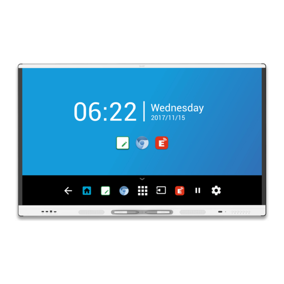
CHAPTER 1 WELCOME Feature Description Touch support You can do everything on the display that you can do at your computer— open and close applications, meet with others, create new documents or edit existing ones, visit websites, play and manipulate videos, and so on— by touching the display’s surface. -
Page 14: Screen
CHAPTER 1 WELCOME Name More information Screen Page 4 Front control panel Page 5 Light sensor Page 6 Remote control sensor / status light Page 3 Pen (×2) Page 4 Speakers Page 6 Page 5 Front connector panel Side connector panel Page 24 Not pictured AC switch Page 33 Bottom connector panel Page 25 Remote control... -
Page 15: Front Connector Panel
CHAPTER 1 WELCOME CAUTION When you return a pen to the magnetic holder, make sure it’s centered in its holder to keep it from falling and being damaged. Front connector panel The front connector panel includes connectors for USB peripherals and a computer or other input source. Name Procedure USB 2.0 Type-A connector... -
Page 16: Accessories
CHAPTER 1 WELCOME Ambient light sensor The ambient light sensor can detect the room brightness and adjust the display’s brightness. Make sure Auto is enabled in Brightness and volume in Settings. See Brightness and volume on page 63. Internal speakers The display includes two 10 W rms integrated speakers. You can also connect external speakers (see Connecting external speakers on page 23). -
Page 17: More Information
CHAPTER 1 WELCOME USB extenders As noted in Connecting cables for room computers, guest laptops and other input sources on page 21, the USB connection between the display and computer should be no longer than 16' (5 m). If you need to connect a computer that is more than 16' (5 m) from the display, use one of the following USB extenders: Extender Specifications... -
Page 19: Chapter 2: Installing The Display
Chapter 2 Installing the display Moving the display to the installation site Using transportation aides Accommodating doorways, hallways and elevators Dealing with cracked, chipped or shattered glass Saving the original packaging Installing the display on a wall Choosing a location Choosing a height Assessing the wall Selecting mounting hardware... -
Page 20: Using Transportation Aides
CHAPTER 2 INSTALLING THE DISPLAY IMPORTANT Move the display at your own risk. SMART cannot accept liability for damages or injury that occur during the display’s transportation. When moving the display Follow local safety regulations and standards. Keep the display in its original packaging. Move the display so that its top frame faces up. -
Page 21: Installing The Display On A Wall
CHAPTER 2 INSTALLING THE DISPLAY Dealing with cracked, chipped or shattered glass The display contains safety-tempered glass. Although this glass is heat-strengthened to help withstand impacts, the glass can crack, chip or shatter if struck with enough force. (Safety glass is designed to break into small pieces rather than sharp shards if it is broken.) Temperature changes can cause a minor crack or chip to become worse, possibly causing the glass to shatter. -
Page 22: Choosing A Location
CHAPTER 2 INSTALLING THE DISPLAY Choosing a location A display is typically installed at the room’s focal point, such as at the front of a classroom or meeting space. Selecting an appropriate location for the display is crucial for ensuring the best possible experience with the product. - Page 23 CHAPTER 2 INSTALLING THE DISPLAY Factor Considerations Visibility The display’s screen is clearly visible to all users in the room. SMART recommends users sit within a 178° viewing area: NOTE The viewing area depends on the display’s resolution and a variety of other factors.
-
Page 24: Choosing A Height
CHAPTER 2 INSTALLING THE DISPLAY Factor Considerations Environment and The location meets the environmental requirements in the display’s ventilation specifications (see More information on page 7). The display isn’t subjected to strong vibrations or dust. Ventilation systems don’t blow air directly on the display. There is adequate ventilation or air conditioning around the display so that heat can flow away from it and the mounting equipment. -
Page 25: Selecting Mounting Hardware
CHAPTER 2 INSTALLING THE DISPLAY NOTE Refer to the display’s specifications for its weight (see More information on page 7). In some situations, you may need to request an engineering analysis to determine if the wall can support the display. Selecting mounting hardware The mounting hardware required for installation varies according to the type of wall onto which the display is being mounted. - Page 26 CHAPTER 2 INSTALLING THE DISPLAY There are a number of potential hazards of mounting a display in a non-standard orientation or angle: Mounting a display horizontally (like a table top) can cause the glass to sag, damaging the display or interfering with the display’s touch system. Non-standard orientation can affect ventilation, creating hotpots in equipment, premature failures and, in displays that use projectors, exploding projector bulbs.
- Page 27 CHAPTER 2 INSTALLING THE DISPLAY If you’re not using the included bolts to fasten the wall mount to the display, see the following table. SMART Board Part number 14 mm + x mm MX165 1031028 where x is the combined thickness of the Minimum M6 wall mount and washer length...
-
Page 28: Installing The Display On A Stand
CHAPTER 2 INSTALLING THE DISPLAY SMART Board Minimum M8 14 mm + x mm MX186 length where x is the combined thickness of the wall mount and washer Maximum M8 bolt 30 mm + x mm length where x is the combined thickness of the wall mount and washer Fasten force 97.36–177.01 in-lb. -
Page 29: Chapter 3: Connecting Power, Cables And Devices
Chapter 3 Connecting power, cables and devices Connecting power Connecting to a network Connecting cables for room computers, guest laptops and other input sources Using recommended cables Connecting to the side connector panel Connecting to the bottom connector panel Connecting to the front connector panel Viewing a connected computer or other device’s input Connecting external speakers Connecting room control systems... -
Page 30: Connecting Power
CHAPTER 3 CONNECTING POWER, CABLES AND DEVICES Connecting power SBID-MX165 SBID-MX175 SBID-MX186 Connect the supplied power cable from the AC power inlet on the side of the display to a power outlet. NOTE Refer to the display’s specifications for power requirements and power consumption information (see More information on page 7). -
Page 31: Connecting Cables For Room Computers, Guest Laptops And Other Input Sources
CHAPTER 3 CONNECTING POWER, CABLES AND DEVICES Connecting cables for room computers, guest laptops and other input sources You can connect cables to the display so that users can connect and use room computers, guest laptops or other devices, such as Blu-ray™ disc players. Using recommended cables SMART recommends the following varieties of cable: Cable type... -
Page 32: Connecting To The Bottom Connector Panel
CHAPTER 3 CONNECTING POWER, CABLES AND DEVICES NOTES The USB Type-B connector for touch control is located on the bottom connector panel. See Connecting to the bottom connector panel below. You can connect a wireless USB keyboard and mouse to the two USB Type-A connectors. Connecting to the bottom connector panel The bottom connector panel includes a video connector and USB connector:... -
Page 33: Connecting External Speakers
CHAPTER 3 CONNECTING POWER, CABLES AND DEVICES Viewing a connected computer or other device’s input Users can use the Input app or tap the Input button to open the input selection menu. Tap an input source to view the computer or other device’s input on the display. For information about viewing a connected device’s input, see the SMART Board MX100 series interactive display user’s guide (smarttech.com/kb/171289). -
Page 34: Connector Reference
CHAPTER 3 CONNECTING POWER, CABLES AND DEVICES NOTE Displays are not compatible with centralized remote control systems, such as a universal remote control. Connector reference Side connector panel The following diagram and table present the connectors on the display’s connector panel: smarttech.com/kb/171288... -
Page 35: Bottom Connector Panel
CHAPTER 3 CONNECTING POWER, CABLES AND DEVICES Connector Connects to Notes HDMI 1.4 out (HDCP- External monitor This connector is HDCP- compliant) encrypted HDMI. NOTE HDMI out is an optional feature. Contact your authorized SMART reseller (smarttech.com/where) for further ordering instructions. USB 2.0 Type-A USB drives and other Connect USB drives and other... -
Page 36: Front Connector Panel
CHAPTER 3 CONNECTING POWER, CABLES AND DEVICES Connector Connects to Notes USB 2.0 Type-B HDMI 1, HDMI 2 or VGA See page 21. input (touch) RS-232 Room control system See page 67. Stereo 3.5 mm out External speakers or audio See page 23. system S/PDIF out Optical digital audio output... -
Page 37: Other Connectors
CHAPTER 3 CONNECTING POWER, CABLES AND DEVICES Other connectors There are additional connectors on the bottom of the display (see Installing the display on a wall on page 11 and Appendix B: Remotely managing the display on page 67). smarttech.com/kb/171288... -
Page 39: Chapter 4: Configuring The Display
Chapter 4 Configuring the display Connecting to a network Configuring the display’s network connection Connecting the display to a network After you have mounted the display and connected power and devices, you can start it for the first time. Connecting to a network You can connect the display to a network using either Wi-Fi or an Ethernet connection. - Page 40 CHAPTER 4 CONFIGURING THE DISPLAY To configure the network 1. Open the required TCP/UDP ports: Protocol Port range Feature e³ experience system software update 56789 EShare app 25123 EShare app 8121 EShare app 8000 EShare app 8001 EShare app 48689 EShare app 25123 EShare app...
- Page 41 CHAPTER 4 CONFIGURING THE DISPLAY To connect to a Wi-Fi network 1. On the display, tap the Home button on the screen to open the launcher. 2. Tap Settings. 3. Tap Network. 4. Ensure Wi-Fi is enabled and Ethernet is disabled. 5.
-
Page 43: Chapter 5: Turning On Your Display For The First Time
Chapter 5 Turning on your display for the first time Turn on the display after mounting it and connecting power and devices. To turn on and set up the display for the first time 1. Flick the switch beside the AC power inlet to the ON (I) position. SBID-MX165 SBID-MX175 SBID-MX186... - Page 44 CHAPTER 5 TURNING ON YOUR DISPLAY FOR THE FIRST TIME 7. Name the display, and then tap Next. 8. If the display isn’t using a wired network connection, select a wireless network, and then tap Next. 9. Tap Finish. The Welcome screen appears. 10.
-
Page 45: Chapter 6: Orienting The Display
Operating Procedure system Windows® 10 a. Select Start. b. Scroll to and select SMART Technologies > SMART Settings. Windows 8 a. Open the Apps screen. b. Scroll to and select SMART Technologies > SMART Settings. Windows 7 Select Start > All Programs > SMART Technologies >... - Page 46 CHAPTER 6 ORIENTING THE DISPLAY 4. Continue until you’ve pressed all the targets. The orientation window closes. smarttech.com/kb/171288...
-
Page 47: Chapter 7: Maintaining The Display
Chapter 7 Maintaining the display Checking the display installation Cleaning the screen Cleaning the touch sensors Maintaining ventilation Preventing condensation Replacing the pens Turning the display off and back on Resetting the display Removing and transporting the display Updating the e³ experience Applying an e³... -
Page 48: Cleaning The Screen
CHAPTER 7 MAINTAINING THE DISPLAY Cleaning the screen Follow these instructions to clean the screen without damaging its anti-glare coating or other product components. CAUTION Do not use permanent or dry-erase markers on the screen. If dry-erase markers are used on the screen, remove the ink as soon as possible with a lint-free, non-abrasive cloth. -
Page 49: Maintaining Ventilation
CHAPTER 7 MAINTAINING THE DISPLAY To clean the IR transmitters and sensors 1. With a clean lint-free, non-abrasive cloth, gently wipe the plastic between the screen and the frame around the perimeter of the display’s screen. 2. If dirt still remains, use 50% isopropyl alcohol (IPS) to clean the protective plastic between the screen and the frame. -
Page 50: Turning The Display Off And Back On
CHAPTER 7 MAINTAINING THE DISPLAY can purchase replacement pens from the Store for SMART Parts (see smarttech.com/Support/PartsStore). Turning the display off and back on In most situations, you can put the display to sleep when not using it following the instructions in the SMART Board MX100 series interactive displays user’s guide (smarttech.com/kb/171289). - Page 51 CHAPTER 7 MAINTAINING THE DISPLAY To remove the display safely, use two or more trained installers. WARNING Do not attempt to move the display by yourself. The display is very heavy. Do not move the display by connecting a rope or wire to the handles on the back. The display can fall and cause injury and product damage.
-
Page 52: Updating The E³ Experience
CHAPTER 7 MAINTAINING THE DISPLAY Updating the e³ experience The display checks for e³ experience system software updates automatically, provided the display’s date and time are set correctly (see Date and time on page 63) and the display is connected to the internet. The display notifies you when an e³ experience system software update is available. - Page 53 CHAPTER 7 MAINTAINING THE DISPLAY using a USB drive. NOTE This will erase all content on your display. Use a USB drive to copy any files you want to keep. 1. Go to smarttech.com/downloads and download the update file for your size of display. 2.
-
Page 55: Chapter 8: Troubleshooting
Chapter 8 Troubleshooting Resolving general issues Resolving issues with power Resolving issues with image or video quality Resolving issues with audio Resolving issues with touch and digital ink Resolving issues with remote management Resolving issues with software Referring to the SMART knowledge base for additional troubleshooting information Contacting your reseller for additional support Finding the display’s serial number The following information helps you resolve a variety of common issues with the display, including... -
Page 56: Resolving General Issues
CHAPTER 8 TROUBLESHOOTING Resolving general issues Issue Solutions You’ve forgotten the lock screen Contact SMART Support. password. You forgot the Settings security Contact SMART Support. password. The display can’t connect to a The wireless network may be operating on bands that the display doesn’t 5 GHz wireless network. -
Page 57: Resolving Issues With Image Or Video Quality
CHAPTER 8 TROUBLESHOOTING Resolving issues with image or video quality Issue Solutions You’re experiencing the following Make sure the display’s firmware is updated to 1.8.7 or later. The display may not or similar issues with image quality: work properly if the display’s firmware is not updated. See Updating the e³ experience on page 42. - Page 58 CHAPTER 8 TROUBLESHOOTING Issue Solutions Colors don’t appear correctly. Minor differences in colors across displays are common. This issue is not unique to SMART products. If you’re using a VGA video input, use a different cable or connect a different source to see if the issue is with the cable or input source.
- Page 59 No image or a low resolution image The SMART Board MX100 series interactive display supports only HDCP- appears on a device you’ve protected HDMI output. If a device you connect to the display’s HDMI out port connected to the display’s HDMI...
-
Page 60: Resolving Issues With Audio
CHAPTER 8 TROUBLESHOOTING Resolving issues with audio Issue Solutions You’re experiencing the following Turn up the computer’s volume. or similar issues with audio: If you’re using external speakers, make sure the speakers are turned on. Make sure the cables connecting the display to the computer are securely No sound is coming from the fastened. -
Page 61: Resolving Issues With Touch And Digital Ink
CHAPTER 8 TROUBLESHOOTING Resolving issues with touch and digital ink Issue Solutions You’re experiencing the following If you’re using two pens, make sure they’re at least 2" (5 cm) apart. or similar issues with touch and Make sure you are not holding the pen near its tip, and that the pen is at a right digital ink: angle (90°) to the screen. -
Page 62: Resolving Issues With Remote Management
CHAPTER 8 TROUBLESHOOTING Issue Solutions Remove any external infrared light sources such as sunlight, incandescent or arc lights, desk lamps and infrared audio devices or move the display to another location in the room. Remove the display from the wall, calibrate it and confirm if this resolves the issue. -
Page 63: Resolving Issues With Software
CHAPTER 8 TROUBLESHOOTING Issue Solutions The display doesn’t respond The display is in a Power Saving mode in which the RS-232 control system is not to a control command yet operating. Commands are not followed Ensure the display is in a power state in which the RS-232 control system is by a command prompt that ready to receive commands. -
Page 64: Finding The Display's Serial Number
CHAPTER 8 TROUBLESHOOTING Your reseller might ask you for the serial number for the display or the iQ appliance. Finding the display’s serial number The display’s serial number is located in the following places: On the bottom frame On the back of the display In the display and e³... -
Page 65: Chapter 9: Troubleshooting The E³ Experience
Chapter 9 Troubleshooting the e³ experience Resolving general issues Resolving issues with Whiteboard Resolving issues with Browser Resolving issues with Input Resolving issues with EShare Resolving issues with iMirror Resolving issues with File Manager This appendix explains how to troubleshoot the e³ experience. Resolving general issues Issue Solutions... -
Page 66: Resolving Issues With Whiteboard
CHAPTER 9 TROUBLESHOOTING THE E³ EXPERIENCE Resolving issues with Whiteboard Issue Solutions The pen isn’t working correctly. Select the pen tool before drawing. See SMART Board MX100 series interactive displays user’s guide (smarttech.com/kb/171288). The Whiteboard app doesn’t support writing with two pens. Use SMART software like SMART Notebook to draw with two pens. -
Page 67: Resolving Issues With Input
CHAPTER 9 TROUBLESHOOTING THE E³ EXPERIENCE Resolving issues with Input Issue Solutions There is an issue with the image. See Resolving issues with image or video quality on page 47for more information. No signal appears on the screen. Connect the computer to one of the display’s video input connectors. NOTE In the input source menu, video input connectors that have a device connected are blue. -
Page 68: Resolving Issues With Eshare
CHAPTER 9 TROUBLESHOOTING THE E³ EXPERIENCE Issue Solutions There is an issue with audio See Resolving issues with audio on page 50. Make sure the computer isn’t muted. Turn up the computer’s volume. Turn up the display’s volume. See Front control panel on page 5. Make sure the display isn’t muted. -
Page 69: Resolving Issues With Imirror
CHAPTER 9 TROUBLESHOOTING THE E³ EXPERIENCE Issue Solutions The EShare app on the display is Make sure the display is connected to a network that has Internet access. not activated. a. Restart the display. See SMART Board MX100 series interactive displays installation and maintenance guide (smarttech.com/kb/171288). - Page 70 CHAPTER 9 TROUBLESHOOTING THE E³ EXPERIENCE Issue Solutions There is an issue with the USB drive Connect to the USB port for the display. See Front connector panel on page 5. Make sure the USB drive is FAT formatted. Make sure the USB drive isn’t encrypted or partitioned. The USB drive is full.
-
Page 71: Appendix A: Adjusting Display And E³ Experience Settings
Appendix A Adjusting display and e³ experience settings Exiting the display’s settings Network Screen lock Advanced Update Recovery About You can access the display and e³ experience’s settings using the Menu button on the front control panel or using the Settings icon in the launcher. -
Page 72: Screen Lock
APPENDIX A ADJUSTING DISPLAY AND E³ EXPERIENCE SETTINGS Option Values Function Notes Get IP address Enable The display automatically acquires Enabling Wi-Fi hotspot allows you to an IP address from a DHCP server connect your mobile device to the automatically Disable on your network display using Wi-Fi for screen sharing. -
Page 73: Advanced
APPENDIX A ADJUSTING DISPLAY AND E³ EXPERIENCE SETTINGS Advanced Option Values Function Notes Display HDMI out 480p Select the output resolution Ensure the device that receives the display’s HDMI out signal matches 1080p the selected output resolution. For best results, make sure all devices from source to sync, use the same resolution settings. - Page 74 APPENDIX A ADJUSTING DISPLAY AND E³ EXPERIENCE SETTINGS Option Values Function Notes Manual [N/A] Sets the display’s brightness Disable Auto to set the brightness manually Volume [N/A] Sets the display’s volume [N/A] OTA server [OTA servers] Sets which server the display Default is Auto.
-
Page 75: Update
APPENDIX A ADJUSTING DISPLAY AND E³ EXPERIENCE SETTINGS Update Option Values Function Notes Firmware version [N/A] Shows technical information about To see the e³ experience system the display’s scalar firmware. software’s version use the About option (see About below). [N/A] Checks for updates to the system If an update is available, the text Update... - Page 76 APPENDIX A ADJUSTING DISPLAY AND E³ EXPERIENCE SETTINGS Option Values Function Notes Android [N/A] Shows the current version of the [N/A] Android operating system on the display MX system version [N/A] Shows the current version of the [N/A] display’s firmware and e³ experience [N/A] Shows the current version of the...
-
Page 77: Appendix B: Remotely Managing The Display
Appendix B Remotely managing the display Configuring the serial interface settings Communication structure Power states Commands You can connect a control system or terminal emulation program on your computer to the display's room control input and remotely select video inputs, change power and sleep states, and get information about the display’s current settings, such as current input source, contrast and power state. -
Page 78: Configuring The Serial Interface Settings
APPENDIX B REMOTELY MANAGING THE DISPLAY Configuring the serial interface settings Configure the control system or computer’s serial interface before sending commands to the display. To configure the serial interface settings 1. Turn on the display. 2. Turn on the control system or computer, and access the serial data communications settings. 3. - Page 79 APPENDIX B REMOTELY MANAGING THE DISPLAY NOTES The display won’t respond to RS-232 commands when it is in a low power state (soft off). Disable Power saving mode to prevent the display from entering a low power state. See Power saving mode on page 64. When you first turn on the display, the RS-232 connector operates in a special diagnostics mode instead of control mode, and the display won’t respond to control commands.
- Page 80 APPENDIX B REMOTELY MANAGING THE DISPLAY NOTES Use ASCII formatted commands. Commands aren’t case-sensitive. When manually entering commands into a terminal emulation program, review each entry carefully before you press ENTER to send a carriage return (0x0d) to terminate the command.
-
Page 81: Power States
APPENDIX B REMOTELY MANAGING THE DISPLAY To increase or decrease the value of a setting Use the set command to increase or decrease the value by a designated number. This example increases the volume by 5: >set volume+5 volume=70 > This example decreases the volume by 15: >set volume-15 volume=55... -
Page 82: Commands
APPENDIX B REMOTELY MANAGING THE DISPLAY With the exception of get powerstate and set powerstate, commands are available only when the display is in ON power state. Commands Get command Set command Response get powerstate set powerstate[Value] powerstate=[Value] Where [Value] is one of the following: Where [Value] is one of the following: = on = ready... - Page 83 APPENDIX B REMOTELY MANAGING THE DISPLAY Get command Set command Response get brightness set brightness[Value] brightness=[Value] Where [Value] is one of the following: Where [Value] is a number between 5 and 100 +[Value] -[Value] NOTE =[5–100] Enabling Auto Brightness overrides any brightness values set manually.
-
Page 85: Appendix C: Identifying The Display
Appendix C Identifying the display To identify your display 1. Press Input on the front control panel. A list of input sources appears. 2. If the input source includes OPS, the display is a SMART Board MX200 series interactive display. The display has an iQ appliance installed. If the input source includes Compute Card, the display is a SMART Board MX300 series interactive display. -
Page 87: Appendix D: Supported Resolutions
Appendix D Supported resolutions HDMI 1 in, HDMI 2 in and HDMI 3 in Resolution Input source aspect ratio Mode Refresh rate 3840 × 2160 16:9 UHD / 2160p 59.94 Hz / 60 Hz 50 Hz 29.97 Hz / 30 Hz 25 Hz 23.98 Hz / 24 Hz 1920 ×... - Page 88 APPENDIX D SUPPORTED RESOLUTIONS Resolution Input source aspect ratio Mode Refresh rate 1024 × 768 XGA 60 60.004 Hz XGA 70 70.069 Hz XGA 75 75.029 Hz 800 × 600 SVGA 60 60.317 Hz SVGA 72 72.188 Hz SVGA 75 75.000 Hz 640 ×...
-
Page 89: Appendix E: Hardware Environmental Compliance
Appendix E Hardware environmental compliance SMART Technologies supports global efforts to ensure that electronic equipment is manufactured, sold and disposed of in a safe and environmentally friendly manner. Waste Electrical and Electronic Equipment and Battery regulations (WEEE and Battery Directives) Electrical and electronic equipment and batteries contain substances that can be harmful to the environment and to human health.
Need help?
Do you have a question about the SMART Board MX100 Series and is the answer not in the manual?
Questions and answers