Table of Contents
Advertisement
Quick Links
Installation and maintenance guide
SBID-MX255-V3 / V3N
SBID-MX255-V3-PW / V3N-PW
SBID-MX055-V3 / V3N
SBID-MX055-V3-PW / V3N-PW
SBID-MX255-V2-C
SBID-MX255-V2-CPW
SBID-MX255-V2
SBID-MX255-V2-PW
SBID MX365
IDX55-3
Was this document helpful?
smarttech.com/docfeedback/171555
SMART Board
MX
|
MX Pro
series interactive displays
|
SBID-MX265-V3 / V3N
|
SBID-MX265-V3-PW / V3N-PW
|
SBID-MX065-V3 / V3N
|
SBID-MX065-V3-PW / V3N-PW
|
SBID-MX265-V2-C
|
SBID-MX265-V2-CPW
|
SBID-MX265-V2
|
SBID MX265-V2-PW
|
SBID-MX375
|
SBID-MX386
|
IDX65-3
|
IDX75-3
|
IDX86-3
®
|
SBID-MX275-V3 / V3N
|
SBID-MX286-V3 / V3N
|
SBID-MX275-V3-PW / V3N-PW
|
SBID-MX075-V3 / V3N
|
SBID-MX086-V3 / V3N
|
SBID-MX075-V3-PW / V3N-PW
|
SBID-MX275-V2-C
|
SBID-MX286-V2-C
|
SBID-MX275-V2-CPW
|
SBID-MX286-V2-CPW
|
SBID-MX275-V2
|
SBID-MX286-V2
|
SBID-MX275-V2-PW
|
SBID-MX286-V2-PW
|
SBID MX265
|
SBID-MX275
|
SBID-MX286
|
IDX55-2
|
IDX65-2
|
IDX75-2
|
IDX86-2
|
SBID-MX286-V3-PW / V3N-PW
|
SBID-MX086-V3-PW / V3N-PW
Advertisement
Chapters
Table of Contents
Troubleshooting

Related Manuals for Smart Technologies Smart Board MX Series


Summary of Contents for Smart Technologies Smart Board MX Series
- Page 1 SMART Board ® MX Pro series interactive displays Installation and maintenance guide SBID-MX255-V3 / V3N SBID-MX265-V3 / V3N SBID-MX275-V3 / V3N SBID-MX286-V3 / V3N SBID-MX255-V3-PW / V3N-PW SBID-MX265-V3-PW / V3N-PW SBID-MX275-V3-PW / V3N-PW SBID-MX286-V3-PW / V3N-PW SBID-MX055-V3 / V3N SBID-MX065-V3 / V3N SBID-MX075-V3 / V3N SBID-MX086-V3 / V3N SBID-MX055-V3-PW / V3N-PW...
- Page 2 Learn more This guide and other resources for SMART Board MX and MX Pro series interactive displays are available in the Support section of the SMART website (smarttech.com/support). Scan this QR code to view these resources on your mobile device. ENERGY STAR is the government-backed symbol for energy efficiency, providing simple, credible, and unbiased information that consumers and businesses rely on to make well-informed decisions.
-
Page 3: Important Information
Important information Important There are critical software updates for the display that you need to install to ensure the display is fully functional and provides the best experience. Connect the display to a wired or wireless network with Internet access to automatically download and apply these updates as well as future updates. Warning Failure to follow the installation instructions included with the display could result in injury and product damage which may not be covered by the warranty. - Page 4 Important information Do not move or mount the display by connecting rope or wire to its handles. The display is heavy, and failure of the rope, wire or handle could lead to injury. ® Use only VESA -approved mounts if using a mount other than the one supplied with the display.. Disconnect all of the display’s power cables from the wall outlet and seek assistance from qualified service personnel if any of the following occur: The power cable or plug is damaged...
- Page 5 Important information You must connect the USB cable that came with the display to a computer that has a USB compliant interface and that bears the USB logo. In addition, the USB source computer must be compliant with IEC 62368-1. The source computer must be CE marked and carry safety certification marks for Canada and USA.
- Page 6 Important information Important smarttech.com/kb/171555...
- Page 7 Important information The following are the normal operating power requirements for the display, including speakers: Model Power requirements SBID-MX255-V3 / SBID-MX255-V3- 100V to 240V AC, 50 Hz to 60 Hz, 90 W PW / SBID-MX055-V3 / SBID- MX055-V3-PW / SBID-MX255-V3N / SBID-MX255-V3N-PW / SBID- MX055-V3N / SBID-MX055-V3N-PW SBID-MX265-V3 / SBID-MX265-V3-...
- Page 8 Important information For additional requirements and other information, refer to the display’s specifications (see More information on page 19). smarttech.com/kb/171555...
-
Page 9: Table Of Contents
Contents Important information Chapter 1 Welcome About this guide About the display Identifying your specific model Accessories More information Chapter 2 Installing the display Moving the display to the installation site Installing the display on a wall Installing the display on a stand Installing the iQ appliance and Intel Compute Card Connecting to a network Connecting power and turning on the display for the first time... - Page 10 Contents The pens and erasers aren’t working as expected iQ apps aren’t working as expected SMART software on connected computers isn’t working as expected The SMART OPS PC module isn’t working as expected The Intel Compute Card isn’t working as expected Contacting your reseller for additional support Appendix A Adjusting iQ settings Network settings...
- Page 11 Contents Commands Appendix E Enrolling the display in SMART Remote Management Certification and compliance smarttech.com/kb/171555...
-
Page 12: About This Guide
Chapter 1 Welcome About this guide About the display Touch Writing, drawing, and erasing iQ experience Display Audio Network connectivity Room computers and guest laptops Accessory slot Front control panel Front connector panel Ambient light sensor Power status light Remote control and IR sensor Identifying your specific model Accessories SMART OPS PC module... -
Page 13: Chapter 1 Welcome
Chapter 1 Welcome This guide is intended for those who install and maintain displays in their organizations. Other documentation and resources are available for those who use displays (see More information on page 19). About the display ® The SMART Board MX or MX Pro interactive display with iQ is the hub of your classroom. -
Page 14: Iq Experience
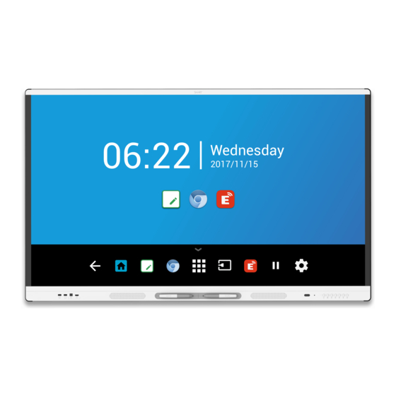
Chapter 1 Welcome iQ experience The display’s iQ experience provides one-touch access to collaborative tools, including a whiteboard, wireless screen sharing, and a web browser. With minimal network integration, there’s no need for wires, cables, or manual software and firmware updates. From the iQ experience Home screen, you can open the iQ apps, switch inputs, and adjust settings. -
Page 15: Room Computers And Guest Laptops
Chapter 1 Welcome You can connect to a network using Wi-Fi or the RJ45 LAN jack on the display: Wi-Fi supports both 2.4 and 5 GHz bands. The two RJ45 jacks allow you to connect the display and an external device, such as a computer, to a Ethernet network. -
Page 16: Front Control Panel
Chapter 1 Welcome Caution The accessory slot’s maximum available power is 60 W. The slot is not a limited power source. To reduce the risk of fire, make sure that accessories connecting to the slot satisfy the fire enclosure requirements of IEC 62368-1. Front control panel The front control panel contains buttons for turning the display on and off, controlling the volume, freezing and unfreezing the screen, and showing and hiding a screen shade. -
Page 17: Identifying Your Specific Model
Chapter 1 Welcome For more information about the remote control, see the SMART Board MX and MX Pro series interactive displays user guide (smarttech.com/kb/171554). Identifying your specific model There are several series of SMART Board MX and MX Pro series interactive displays: SMART Board MX (V3) SMART Board MX (V2- SMART ... -
Page 18: Smart Ops Pc Module
Chapter 1 Welcome SMART OPS PC module Stands USB extenders Note For more information about these and other accessories, see smarttech.com/accessories. SMART OPS PC module SMART Open Pluggable Specification (OPS) PC modules provide a hassle- ® ™ free Windows Pro installation based on Intel Core processors and are designed specifically to work with a SMART display. -
Page 19: More Information
Chapter 1 Welcome Notes To extend touch using the SMART CAT 5 USB extender (CAT5-XT-1100) use a touch USB connector associated with an HDMI 1, HDMI 2, or VGA input. The extender will not function correctly if used to extend touch associated with the HDMI 3 input on the front of the display. For more information about extending USB connections, see USB cable extenders. -
Page 20: Chapter 2 Installing The Display
Chapter 2 Installing the display Moving the display to the installation site Using transportation aides Accommodating doorways, hallways, and elevators Dealing with cracked, chipped, or shattered glass Saving the original packaging Installing the display on a wall Choosing a location Choosing a height Assessing the wall Selecting mounting hardware... -
Page 21: Using Transportation Aides
Chapter 2 Installing the display Important Move the display at your own risk. SMART cannot accept liability for damages or injury that occur during the display’s transportation. When moving the display: Follow local safety regulations and standards. Pack the display in its original packaging, including the pallet. Move the display so that its top frame faces up. -
Page 22: Installing The Display On A Wall
Chapter 2 Installing the display Dealing with cracked, chipped, or shattered glass The display contains safety-tempered glass. Although this glass is heat-strengthened to help withstand impacts, the glass can crack, chip or shatter if struck with enough force. (Safety glass is designed to break into small pieces rather than sharp shards if it is broken.) Temperature changes can cause a minor crack or chip to become worse, possibly causing the glass to shatter. -
Page 23: Choosing A Location
Chapter 2 Installing the display Choosing a location A display is typically installed at the room’s focal point, such as at the front of a classroom or meeting space. Selecting an appropriate location for the display is crucial for ensuring the best possible experience with the product. - Page 24 Chapter 2 Installing the display Factor Considerations Visibility The display’s screen is clearly visible to all users in the room. SMART recommends users sit within a 178° viewing area: Note The viewing area depends on the display’s resolution and a variety of other factors.
-
Page 25: Choosing A Height
Chapter 2 Installing the display Factor Considerations Environment and The location meets the environmental requirements in the display’s specifications (see More information on page 19). ventilation The display isn’t subjected to strong vibrations or dust. Ventilation systems don’t blow air directly on the display. There is adequate ventilation or air conditioning around the display so that heat can flow away from it and the mounting equipment. -
Page 26: Selecting Mounting Hardware
Chapter 2 Installing the display In some situations, you may need to request an engineering analysis to determine if the wall can support the display. Selecting mounting hardware The mounting hardware required for installation varies according to the type of wall onto which the display is being mounted. - Page 27 Chapter 2 Installing the display Mount the display vertically (90° relative to the floor plus or minus 2° for tolerance) and in landscape orientation. SMART doesn’t support mounting the display at other angles or in portrait orientation. Use the included wall mount. Optionally, use a VESA-approved mounting plate that is rated for the display’s weight and size.
-
Page 28: Installing The Display On A Stand
Installing the iQ appliance and Intel Compute Card For SMART Board MX series displays For more information about installing the iQ appliance in SMART Board MX series displays, see the SMART Board MX series interactive display installation instructions (smarttech.com/kb/171274). Caution Install the AM50 iQ appliance and Intel Compute Card before you turn on the display for the first time. -
Page 29: Connecting To A Network
Chapter 2 Installing the display Connecting the Intel Compute Card With the SBID-MX365, SBID-MX375, and SBID-MX386 models, you can insert an Intel Compute Card in the slot on the AM50 iQ appliance to access the card’s Windows 10 operating system from the display. Important Make sure the Intel Compute Card is inserted before you turn on the display. -
Page 30: Am50 Iq Appliance
Chapter 2 Installing the display If you’re using one of the display’s RJ45 jacks to connect to a network, you can connect a computer to the other RJ45 jack to provide network access for the computer (pictured). This is particularly useful if there is only one wired network connection in the room. -
Page 31: Connecting Power And Turning On The Display For The First Time
Chapter 2 Installing the display connect an Ethernet cable from a network outlet to the display’s RJ45 IN jack, and then connect another Ethernet cable from the display’s RJ45 OUT jack to the AM50 appliance’s RJ45 jack Connecting power and turning on the display for the first time The final step in installing and configuring the display is to connect power and turn it on. - Page 32 Chapter 2 Installing the display To turn on and set up the display for the first time Important Install the OPS PC module before you turn the display on. Notes Touch is not available right after waking up the display or turning it on. Wait a few seconds and then the display will respond to touch.
-
Page 33: About Energy Saving Modes
Chapter 2 Installing the display 9. If the display isn’t using a wired network connection, select a wireless network, and then tap Next. Important The display needs an internet connection for downloading and installing important updates. Ask the network administrator to confirm that the network has been correctly configured for the iQ experience. -
Page 34: Chapter 3 Connecting Computers And Other Devices
Chapter 3 Connecting computers and other devices Installing SMART software Connecting room computers and guest laptops Viewing a connected computer’s input Setting a connected computer’s resolution and refresh rate Connecting USB drives, peripherals, and other devices Troubleshooting connected computers Connecting a SMART OPS PC module Connecting other devices Connecting USB drives, peripherals, and other devices Connecting an external display... -
Page 35: Installing Smart Software
Chapter 3 Connecting computers and other devices Installing SMART software The display comes with the following software, which you can install on connected computers: Software Description Notes SMART Notebook basic Free software designed for use with a See Find out more about the version SMART Board interactive display. -
Page 36: Connecting Room Computers And Guest Laptops
Chapter 3 Connecting computers and other devices Contact your authorized SMART reseller (smarttech.com/where) for information about purchasing SMART software. You can download SMART software from smarttech.com/downloads and install it following the instructions in Installing and maintaining SMART Notebook, Installing SMART TeamWorks, or Installing and maintaining SMART ... - Page 37 Chapter 3 Connecting computers and other devices SMART Board MX (V2-C) series Side and bottom connector panels Front connector panel smarttech.com/kb/171555...
- Page 38 Chapter 3 Connecting computers and other devices SMART Board MX (V2) series Side and bottom connector panels Front connector panel HDMI 3 smarttech.com/kb/171555...
- Page 39 Chapter 3 Connecting computers and other devices SMART Board MX series Side and bottom connector panels Front connector panel HDMI 1 HDMI 3 HDMI 2 Notes Install SMART software on any computers you connect to the display (see Installing SMART software on page ...
-
Page 40: Viewing A Connected Computer's Input
Chapter 3 Connecting computers and other devices You can charge devices connected to the USB Type-C receptacle on the font connector panel of SMART Board MX (V2-C and V3) series interactive displays up to 15 W. You can charge devices connected to the USB Type-C receptacle on the side connector panel of SMART Board MX (V3) series interactive displays up to 65 W (if a module is not installed in the accessory slot) or up to 30 W (if a module is installed in the accessory slot). -
Page 41: Setting A Connected Computer's Resolution And Refresh Rate
Chapter 3 Connecting computers and other devices To view the input of a computer connected to a SMART Board MX series display 1. Connect the computer to the display. 2. Press the Input on the front control panel. The Input selection menu appears. Note Inputs with devices connected are blue, and inputs without a connection are black. -
Page 42: Connecting A Smart Ops Pc Module
Chapter 3 Connecting computers and other devices The following table presents the recommend resolutions and refresh rates for the display’s VGA input source: Resolution Input source Mode Refresh rate aspect ratio 1920 × 1080 16:9 [N/A] 60.000 Hz 1600 × 1200 [N/A] 60.000 Hz 1360 ×... -
Page 43: Connecting Other Devices
Chapter 3 Connecting computers and other devices Connecting other devices In addition to computers, you can connect the following devices to the display: USB drives, peripherals, and other devices External displays External audio systems Room control systems Connecting USB drives, peripherals, and other devices The display includes the following USB Type A receptacles. - Page 44 OPS PC (SuperSpeed) (Hi-Speed) Located on the side connector panels of SMART Board MX (V2 and V2-C) series displays Located on the front connector panels of all displays and on the side connector panel of SMART Board MX series displays smarttech.com/kb/171555...
-
Page 45: Connecting An External Display
SMART Board MX (V2 and V2- C) series SMART Board MX series In addition to the stereo 3.5 mm out connector, the display provides a Sony/Philips Digital Interface (S/PDIF) out connector (pictured). S/PDIF is a digital audio transmission medium. You need an audio system that has an S/PDIF input to decode this connection to analog. -
Page 46: Connecting Room Control Systems
Chapter 3 Connecting computers and other devices SMART Board MX (V3) series SMART Board MX (V2 and V2- SMART Board MX series C) series Note The S/PDIF audio is a fixed-volume output. Adjusting the display’s volume for its internal speakers does not affect the volume output of the S/PDIF port. -
Page 47: Connector Diagrams
Chapter 3 Connecting computers and other devices Connector diagrams SMART Board MX (V3) series Connector panel The following diagram and table present the connectors on the display’s connector panel: Side Bottom Connector Connects to Notes See page 36 and USB cables and USB Type-C USB Type-C 2 input connectors. -
Page 48: Front Connector Panel
Chapter 3 Connecting computers and other devices Connector Connects to Notes S/PDIF out Digital audio output See page 45 and Digital audio cables and connectors. HDMI 2.0 out External display See Connecting an external display on page 45 and HDMI cables and connectors. -
Page 49: Smart Board Mx (V2 And V2-C) Series
Chapter 3 Connecting computers and other devices Connector Connects to Notes USB 3.0 Type-B See page 36 and USB cables and HDMI 3 input (touch) connector connectors. USB 2.0 Type-A Supported USB drives, See page 43 and USB cables and peripherals, and other connectors. -
Page 50: Front Connector Panel
Chapter 3 Connecting computers and other devices Connector Connects to Notes HDMI 2.0 in HDMI 1 input See page 36 and HDMI cables and (video and audio) connectors. USB 3.0 Type-B HDMI 2 input (touch) See page 36 and USB cables and connectors. -
Page 51: Smart Board Mx Series
Chapter 3 Connecting computers and other devices Connector Connects to Notes USB 2.0 Type-A Supported USB drives Connect a USB drive to update the connector display’s firmware. USB 2.0 Type-B See page 36 and USB cables and HDMI 3 input (touch) connector connectors. - Page 52 Chapter 3 Connecting computers and other devices Connector Connects to Notes HDMI 1.4 out (HDCP- External monitor This connector is HDCP-encrypted compliant) HDMI. Note HDMI out is an optional feature. Contact your authorized SMART reseller (smarttech.com/where) for further ordering instructions. USB 2.0 Type-A Supported USB drives, Connect a USB ...
-
Page 53: Front Connector Panel
Chapter 3 Connecting computers and other devices Front connector panel The following diagram and table present the connectors on the display’s front connector panel: Connector Connects to Notes USB 2.0 Type-A Supported USB drives, See page 43 and USB cables and peripherals, and other connectors. -
Page 54: Turning Off, Turning On, And Resetting The Display
Turning off, turning on, and resetting the display Turning off, turning on, and resetting SMART Board MX (V3, V2 and V2-C) series displays Turning off, turning on, and resetting SMART Board MX series displays Cleaning and maintaining hardware Checking the display installation... -
Page 55: Chapter 4 Maintaining The Display
Chapter 4 Maintaining the display In most situations, you can put the display into Sleep or Standby when not using it following the instructions in the SMART Board MX and MX Pro series interactive displays user guide (smarttech.com/kb/171554). In some situations, such as when you transport the display or clean its screen, you need to turn the display off. -
Page 56: Cleaning And Maintaining Hardware
Chapter 4 Maintaining the display Turning off, turning on, and resetting SMART Board MX series displays To turn the display off Press the Power button on the front control panel for two seconds. To turn the display back on Press the Power button on the front control panel. -
Page 57: Cleaning The Touch Sensors
Chapter 4 Maintaining the display Do not use cleaning solutions or glass cleaners on the screen, because they can deteriorate or discolor the screen. To clean the screen 1. Turn off any connected computers. 2. Turn off the display (see Turning off, turning on, and resetting the display on page 54). 3. -
Page 58: Maintaining Ventilation
Chapter 4 Maintaining the display Maintaining ventilation The display requires proper ventilation. Dust buildup in the ventilation holes compromises cooling and can lead to product failure. Clean accessible ventilation holes monthly with a dry cloth. Use a vacuum cleaner with a narrow hose end fitting to clear the back ventilation holes regularly. You might have to remove the display from the wall. -
Page 59: Configuring Your Organization's Network For Smart Mirror
Chapter 4 Maintaining the display To remove the display safely, use two or more trained installers. Warning Do not attempt to move the display by yourself. The display is very heavy. Do not move the display by connecting a rope or wire to the handles on the back. The display can fall and cause injury and product damage. -
Page 60: Configuring The Network For Devices Sharing Their Screens Using Google Cast, Airplay, Or The Smart Mirror App
Chapter 4 Maintaining the display Network administrators need to configure the network so users can share their devices’ screens. Use the following information to configure the network. You’ll also need to configure the network so all features of the iQ experience function properly. See Configuring your organization’s network for a SMART Board display with iQ. - Page 61 Chapter 4 Maintaining the display 2. Enable the following ports for screen sharing using Google Cast or Airplay: Note Even if your network is open, the following ports need to be open for SMART Mirror. Protocol Port range Feature 1-65535 (Select from available ones) 1025-65535 5353...
-
Page 62: Smart Mirror Troubleshooting Wizards
Chapter 4 Maintaining the display 3. If Layer 7 filtering or a proxy with protocol filtering has been applied to the ports above, then administrators will need to allow the following protocols: HTTP HTTPS DTLS XMPP Bonjour protocols SRTP STUN TURN 4. -
Page 63: Configuring The Network For Smart Board Mx's Firmware Update
Chapter 4 Maintaining the display Advanced troubleshooting for SMART Mirror Issue Solutions Mobile devices and computers can’t Organizations often block a number of network ports. find the display when using AirPlay Ask the administrator to allow or Google Cast. TCP ports 7000, 8008, 8009, 47000, 7100, 49228, 50259 UDP ports 62572 and 54780 If using Google Cast, UDP port 1900 If using Windows computer or a Mac computer, UDP port 5353. -
Page 64: Updating The Display's Firmware
Chapter 4 Maintaining the display You can connect the display to a network using Wi-Fi or an Ethernet connection. Before connecting the display, your organization’s network administrators need to configure the network to allow users to update the display’s firmware automatically. To configure the network 1. -
Page 65: Updating Iq System Software
Chapter 4 Maintaining the display To make sure the network is configured properly for firmware updates, see Configuring the network for SMART Board MX’s firmware update on page 63. To update the display’s iQ system software, see Updating iQ system software below. Updating iQ system software When the display is connected to the Internet, it updates its system software automatically. -
Page 66: Orienting Your Smart Board Mx Series Display
Procedure system Windows ® a. Select Start. b. Scroll to and select SMART Technologies > SMART Settings. a. Open the Apps screen. Windows 8 b. Scroll to and select SMART Technologies > SMART Settings. Windows 7 Select Start > All Programs > SMART Technologies >... -
Page 67: Chapter 5 Troubleshooting
Chapter 5 Troubleshooting The display isn’t turning on The screen is blank or there’s a problem with the image on the screen There’s no sound or there’s a problem with the sound Touch isn’t working as expected The pens and erasers aren’t working as expected iQ apps aren’t working as expected SMART software on connected computers isn’t working as expected The SMART OPS PC module isn’t working as expected... -
Page 68: The Screen Is Blank Or There's A Problem With The Image On The Screen
Home screen. On SMART Board MX series displays, press Input on the front control panel or the remote control, and then select OPS to switch to the iQ experience and open the Home screen. - Page 69 The image if flickering or flashing. If the Home screen appears correctly, the issue is with the video input. On SMART Board MX series displays, make sure the iQ appliance is securely The image is dim. installed in the accessory slot and its power light is on.
- Page 70 Chapter 5 Troubleshooting Symptom Troubleshooting steps The image is cut off or shifted to the Adjust any connected computers’ video settings, particularly zoom, crop, and left or right. underscan. See the computer’s operating system documentation. If you’re using a VGA video input and any connected computers’ desktops are entirely black, change them to dark gray or a different color.
-
Page 71: There's No Sound Or There's A Problem With The Sound
Chapter 5 Troubleshooting There’s no sound or there’s a problem with the sound Symptom Troubleshooting steps There’s no sound. If you’re using an external audio system, make sure it is turned on. Make sure the cables connecting the display to the computer are securely fastened. There is sound, but the volume is low. -
Page 72: Touch Isn't Working As Expected
Chapter 5 Troubleshooting Touch isn’t working as expected Symptom Troubleshooting steps The display doesn’t respond to Touch is not available right after waking up the display or turning it on. Wait a few touch. seconds and then the display will respond to touch. Make sure SMART Product Drivers are installed and running on connected computers. -
Page 73: The Pens And Erasers Aren't Working As Expected
Chapter 5 Troubleshooting The pens and erasers aren’t working as expected Symptom Troubleshooting steps The display doesn’t respond to touch Make sure SMART Product Drivers are installed and running on connected or writing with a pen. computers. (SMART Board MX (V3) displays require SMART Product Drivers 12.18 or later, and SMART Board MX (V2-C) and (V2) displays require SMART Product Drivers 12.14 or later). -
Page 74: Smart Software On Connected Computers Isn't Working As Expected
Chapter 5 Troubleshooting SMART software on connected computers isn’t working as expected Symptom Troubleshooting steps SMART Notebook software isn’t See Troubleshooting SMART Notebook. working as expected. Lumio by SMART isn’t working as See Troubleshooting common issues in Lumio by SMART. expected. - Page 75 Scan the QR code on the label to view the SMART Board MX or MX Pro series interactive display support pages on the SMART website. For SMART Board MX series displays, the serial number is on labels located on the bottom frame and the back of the display.
-
Page 76: Appendix A Adjusting Iq Settings
Appendix A Adjusting iQ settings Network settings Personalization Application settings System settings SMART Mirror You can access settings using the icon on the Home screen. Notes Settings can apply to a user or to the entire system. User-level settings change depending on the user who is signed in. -
Page 77: Personalization
Appendix A Adjusting iQ settings Option Values Function Notes User or system setting SMART iQ Ethernet Advanced options [N/A] Options available when an Ethernet [N/A] System cable is connected Static IP (Use DHCP) Enables or disables DHCP to assign [N/A] User the display an IP address. -
Page 78: Application Settings
Appendix A Adjusting iQ settings Option Values Function Notes User or system setting Wallpaper [Wallpapers] Select the wallpaper that appears in 1920 × 1080 User the background. images work best The display supports .png and .jpg file formats See Changing the display’s wallpaper. - Page 79 Appendix A Adjusting iQ settings Option Values Function Notes User or system setting Allow OneDrive Enables or disables access to See Opening your User integration in Files OneDrive when you’re signed in Google Drive or Library to your SMART Account. OneDrive on the display.
- Page 80 Appendix A Adjusting iQ settings Option Values Function Notes User or system setting Miracast Enables or disables the Miracast Miracast is enabled by System protocol. default. Important Devices that use AirPlay and Google Cast can’t connect to the display while a Miracast device is connected.
-
Page 81: System Settings
Appendix A Adjusting iQ settings System settings Option Values Function Notes User or system setting System Access to USB mass Enables or disables access to a USB This option is not System storage devices drive. available for SMART Board MX series displays. - Page 82 Appendix A Adjusting iQ settings Option Values Function Notes User or system setting Go to energy saving Disabled Sets the number of minutes of The default is 60 System mode after inactivity before the display enters minutes. 1 min an energy saving mode. This option is not 5 mins available for...
- Page 83 Appendix A Adjusting iQ settings Option Values Function Notes User or system setting Apply power settings If enabled, the display will enter an This option is not System even when displaying an energy saving mode even when an available for external video source external video input is connected.
- Page 84 Appendix A Adjusting iQ settings Option Values Function Notes User or system setting Saturation 0–511 Sets the overall saturation of the This option is not System image. available for SMART Board MX series displays. 0–448 Sets the overall red of the image.. This option is not System available for...
- Page 85 Appendix A Adjusting iQ settings Option Values Function Notes User or system setting Advanced HDMI Settings HDMI 1.0 Sets the HDMI version, HDP pulse You can also System width, and MHL setup delay for each enable or disable HDMI 2.0 HDMI ...
- Page 86 Appendix A Adjusting iQ settings Option Values Function Notes User or system setting Built-in Speakers Enables or disables the display’s When analog System internal speakers. speakers are connected to the display, the display’s internal speakers are disabled automatically. This option is not available for SMART Board MX series...
- Page 87 Appendix A Adjusting iQ settings Option Values Function Notes User or system setting Date [N/A] Sets the display’s date. Disable System Automatic date & time to set the date manually. Time [N/A] Sets the display’s time. Disable System Automatic date &...
- Page 88 Appendix A Adjusting iQ settings Option Values Function Notes User or system setting Support ID [Support ID] Shows the support ID associated Enable this [N/A] with the display. option only on the advice of SMART Support, and only in combination with the board’s Support ID.
- Page 89 Appendix A Adjusting iQ settings Option Values Function Notes User or system setting Security Lock Down Settings [N/A] Lock down the display’s settings See Locking System using a security certificate on a USB down the drive. Settings app for more information.
- Page 90 Appendix A Adjusting iQ settings Option Values Function Notes User or system setting Software Update Updates Channel Stable Channel Sets which iQ system software When switching System updates the display receives. from the Beta Beta Channel channel to the Stable channel, a factory reset occurs.
-
Page 91: Smart Mirror
Appendix A Adjusting iQ settings Option Values Function Notes User or system setting Build Number [N/A] Shows the iQ system software’s [N/A] [N/A] version number. Serial Number [N/A] Shows the display’s serial number [N/A] [N/A] (SMART Board (V2 and V2-C) series displays). - Page 92 Appendix A Adjusting iQ settings Only available on MX (V3) displays. From the SMART Mirror home screen, select Settings General Values Function Notes User or system setting Room Name [N/A] Assign a name to this device for your It’s System network.
- Page 93 Appendix A Adjusting iQ settings Security Values Function Notes User or system setting Lock settings Enable Default is User disabled. Disable Settings can be locked to prevent unwanted changes. If enabled, you will be prompted to enter and confirm a 4-digit lock code to access settings on this device.
-
Page 94: Appendix B Adjusting Display Settings
Network Screen lock Advanced Update Recovery About You can access SMART Board MX series displays’ settings using the Menu button on the front control panel. Exiting the display’s settings Tap Exit press the Menu button on the front control panel... -
Page 95: Screen Lock
Appendix B Adjusting display settings Option Values Function Notes Static IP address Enable Enter a static IP address Use the on-screen keyboard or connect a USB keyboard to the Disable Display USB Type-A connector on the front connector panel to enter information. -
Page 96: Advanced
Appendix B Adjusting display settings Advanced Option Values Function Notes Display Walllpaper [N/A] Sets the background image on the Only .png, .jpg, .bmp files are display supported Save the wallpaper file to a USB drive and insert it into the USB port. -
Page 97: Update
Appendix B Adjusting display settings Option Values Function Notes Power saving mode Enable Enables or disables power saving Enabled by default. mode Disable When enabled, power saving mode activates after 90 minutes of inactivity. Enabling Power saving mode makes RS-232 control of the display unavailable until the display is turned on using the power button on the front control panel . -
Page 98: Recovery
Appendix B Adjusting display settings Recovery Option Values Function Notes Restore user settings [N/A] Resets any options the user may [N/A] have changed Restore factory settings [N/A] Resets all options to their default Only administrators should reset the values display. About Option Values... -
Page 99: Appendix C Managing Smart Board Mx (V3, V2, And V2-C) Series Displays Using
Appendix C Managing SMART Board MX (V3, V2, and V2-C) series displays using RS-232 For SMART Board MX (V3), MX (V3) Pro, MX (V2-C), MX (V2-C) Pro, MX (V2), MX (V2) Pro, and MX Pro series displays. Configuring the serial interface settings Commands and responses Power state commands Input commands... -
Page 100: Configuring The Serial Interface Settings
Appendix C Managing SMART Board MX (V3, V2, and V2-C) series displays using RS-232 MX (V3) and MX (V3) Pro series MX (V2-C), MX (V2-C) Pro, MX (V2), MX (V2) Pro series portant Use only a standard RS-232 cable. Do not use a null modem cable. Null modem cables typically have ends of the same type. - Page 101 Appendix C Managing SMART Board MX (V3, V2, and V2-C) series displays using RS-232 4. Send a carriage return character (<CR>) to the display. The display will show a command prompt (>) to indicate that the display can now accept commands. Note If you’re using a terminal application on a computer, pressing ENTER should send a carriage return character (<CR>) but may also send a line feed character (<LF>), depending on your...
-
Page 102: Commands And Responses
Appendix C Managing SMART Board MX (V3, V2, and V2-C) series displays using RS-232 When using a control system program instead of terminal program, all lines output from the display are preceded by a carriage return character (<CR>) and line feed character (<LF>) and then followed by a carriage return character (<CR>) and line feed character (<LF>), as shown in the example below. - Page 103 Appendix C Managing SMART Board MX (V3, V2, and V2-C) series displays using RS-232 In many terminal applications on a computer, you can use the BACKSPACE key when typing commands. Review each entry carefully before sending a command to the display. Don’t send another command until you receive the response and the next command prompt (>).
-
Page 104: Power State Commands
Appendix C Managing SMART Board MX (V3, V2, and V2-C) series displays using RS-232 To increase or decrease the value of a setting Use the set command to increase or decrease the value by a designated number. This example increases the volume by 5: >set volume+5 volume=70 >... -
Page 105: Power State Commands
Appendix C Managing SMART Board MX (V3, V2, and V2-C) series displays using RS-232 Power state Description READY The screen is off, but the display is ready to turn on when one of the following occurs: A user presses the Power button on the convenience panel or the remote control. -
Page 106: Input Commands
Appendix C Managing SMART Board MX (V3, V2, and V2-C) series displays using RS-232 Input commands Get command Set command Response get input set input[Value] input=[Value] Where [Value] is one of the following: Where [Value] is one of the following: =hdmi1 hdmi1 =hdmi2... -
Page 107: Screen Shade Commands
Appendix C Managing SMART Board MX (V3, V2, and V2-C) series displays using RS-232 Screen shade commands Get command Set command Response get screenshade set screenshade[Value] screenshade=[Value] Where [Value] is one of the following: Where [Value] is one of the following: =off Volume commands Get command... -
Page 108: Model Number Commands
Appendix C Managing SMART Board MX (V3, V2, and V2-C) series displays using RS-232 Model number commands Get command Response get modelnum modelnum=[Value] Where [Value] is one of the following: sbid-mx055-v2 sbid-mx065-v2 sbid-mx075-v2 sbid-mx086-v2 Serial number commands Get command Response get serialnum serialnum=[Value] Where [Value] is the serial number. - Page 109 Appendix C Managing SMART Board MX (V3, V2, and V2-C) series displays using RS-232 Change Asyncronous message Display power state #powerstate=[Value] Where [Value] is one of the following: ready standby powersave updateon updateready Input selection #input=[Value] Where [Value] is one of the following: hdmi1 hdmi2 hdmi3...
-
Page 110: Resolving Issues With Managing The Display Using
Appendix C Managing SMART Board MX (V3, V2, and V2-C) series displays using RS-232 Resolving issues with managing the display using RS-232 The following table presents common issues with managing the display using RS-232 and explains how to resolve them: Symptom Troubleshooting steps Managing the display using RS-232... -
Page 111: Appendix D Managing Smart Board Mx Series Displays Using
Appendix D Managing SMART Board MX series displays using RS-232 For SMART Board MX series displays Configuring the serial interface settings Communication structure Power states Commands You can connect a control system or terminal emulation program on your computer to the display's room control input and remotely select video inputs, change power and sleep states, and get information about the display’s current settings, such as current input source, contrast and power state. -
Page 112: Configuring The Serial Interface Settings
Appendix D Managing SMART Board MX series displays using RS-232 Configuring the serial interface settings Configure the control system or computer’s serial interface before sending commands to the display. To configure the serial interface settings 1. Turn on the display. 2. - Page 113 Appendix D Managing SMART Board MX series displays using RS-232 Notes The display won’t respond to RS-232 commands when it is in a low power state (soft off). Disable Power saving mode to prevent the display from entering a low power state. See Power saving mode on page ...
- Page 114 Appendix D Managing SMART Board MX series displays using RS-232 Notes Use ASCII formatted commands. Commands aren’t case-sensitive. When manually entering commands into a terminal emulation program, review each entry carefully before you press ENTER to send a carriage return (0x0d) to terminate the command. Don’t send another command until you receive the response and the next command prompt.
-
Page 115: Power States
Appendix D Managing SMART Board MX series displays using RS-232 Power states The display has the following power states: Power state Description The display is in normal operating mode. READY The screen is off, but the display is ready to turn on when: A user presses the Power button on the front control panel. - Page 116 Appendix D Managing SMART Board MX series displays using RS-232 Commands Get command Set command Response get powerstate set powerstate[Value] powerstate=[Value] Where [Value] is one of the following: Where [Value] is one of the following: = on = ready ready updateon Notes updateready...
- Page 117 Appendix D Managing SMART Board MX series displays using RS-232 Get command Set command Response get volume set volume[Value] volume=[Value] Where [Value] is one of the following: Where [Value] is a number between 0 and 100 +[Value] -[Value] =[0–100] get mute set mute[Value] mute=[Value] Where [Value] is one of the following:...
- Page 118 Appendix E Enrolling the display in SMART Remote Management Your SMART Board MX or MX Pro series interactive display has a built-in feature that enables you to enroll the display with your organization’s SMART Remote Management account. When you enroll one of these displays, you can use SMART Remote Management to centrally control features and settings for the display, such as: blocklists and allowlists...
- Page 119 Responsible Party – U.S. Contact Information iii. the maximum antenna gain permitted for devices in SMART Technologies Inc. the band 5725-5825 MHz shall comply with the e.i.r.p. 2401 4th Ave., 3rd Floor limits specified for point-to-point and non point-to- Seattle, WA 98121 point operation as appropriate.
- Page 120 The remote control contains alkaline batteries. Recycle or dispose of batteries properly. EU declaration of conformity Hereby SMART Technologies ULC declares that the radio equipment type Interactive displays model IDX55-2, IDX55-3, IDX65-1, IDX65-2, IDX-65-3, IDX75-1, IDX75-2, IDX75-3, IDX86- 1, IDX86-2, IDX86-3, and the OPS AM40, AM50 are in compliance with Directive 2014/53/EU.
- Page 121 SMART Technologies smarttech.com/support smarttech.com/contactsupport smarttech.com/kb/171555...
Need help?
Do you have a question about the Smart Board MX Series and is the answer not in the manual?
Questions and answers