Table of Contents
Advertisement
Quick Links
IMPORTANT INFORMATION:
• A copy of our "Safe Operating Practices" Manuals are always available free of charge either by downloading it from our
Technical Publications website @ www.airwinch.com or by contacting the Factory at (800) 866-5457 for North America and
(206) 624-0466 for International. The Safe Operating Practices manual must be read prior to anyone operating a
Ingersoll-Rand winch or hoist. The manual form numbers are as follows:
"Safe Operating Practices Non-Man Rider™ Winches" Manual, Form No. MHD56250
"Safe Operating Practices for Man Rider™ Winches" Manual, Form No. MHD56251
"Safe Operating Practices for Pneumatic, Hydraulic and Electric Hoists" Manual, Form No. MHD56295
• Available winch options may require additional supplements to the basic winch manual.
• For Man Rider™ winches ensure a copy of the Man Rider™ supplement is made available to the operator prior to winch
operation.
Winch Man Rider
™
Model:
FA2, FA2.5,
FH2, FH2.5
FA5
FA10
FA2.5A
FA2B and
HU40A
FH10MR
Fulcrum Electric
LS500HLP/
LS1000HLP
• We strongly recommend that ALL maintenance on Ingersoll-Rand equipment be carried out by personnel certified by
Ingersoll-Rand, or by Ingersoll-Rand Authorized Service Centers.
• Contact the Factory if in doubt about installation, operation, inspection and maintenance instructions.
• Use only Genuine Ingersoll-Rand parts when maintaining or repairing a winch, hoist or any component of a winch or hoist.
• ANSI / ASME recommends that a winch or hoist (or any components of a winch or hoist) that has been repaired be tested
prior to being placed into service:
*
Winches - ANSI / ASME B30.7 (BASE MOUNTED DRUM HOISTS) Refer to section 7.2.2 - Testing.
*
Hoists - ANSI / ASME B30.16 (OVERHEAD HOISTS - UNDERHUNG) Refer to section 16.2.2 - Testing.
Form MHD56298
Edition 2
November 2004
71441844
© 2004 Ingersoll-Rand Company
Supplements:
Publication No.
MHD56046
MHD56042 and
MHD56220
MHD56252
MHD56236
MHD56207
MHD56212
MHD56277
SAM0004
Model:
Publication No.
LS500RLP
LS1000RLP
LS150RLP
LS150RLP/500/
1000
LS150RLP and
LS150PLP-PH
LS500RLP-E
LS150RLP-
DP5M-F
LS150HLP
Form MHD56298
SAM0011
SAM0012
SAM0082
SAM0115
SAM0120
SAM0122
SAM0184
SAM0222
Advertisement
Chapters
Table of Contents

Related Manuals for Ingersoll-Rand FA2.5A Series


Summary of Contents for Ingersoll-Rand FA2.5A Series
- Page 1 Form MHD56298 IMPORTANT INFORMATION: • A copy of our “Safe Operating Practices” Manuals are always available free of charge either by downloading it from our Technical Publications website @ www.airwinch.com or by contacting the Factory at (800) 866-5457 for North America and (206) 624-0466 for International.
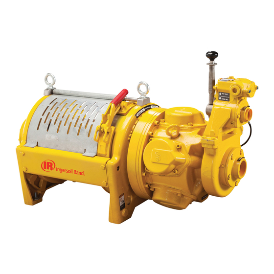
- Page 2 Form MHD56114 PARTS, OPERATION AND MAINTENANCE MANUAL THIRD GENERATION MODEL FA2.5A (Dwg. MHP2415) READ THIS MANUAL BEFORE USING THESE PRODUCTS. This manual contains important safety, installation, operation maintenance information. Make this manual available to all persons responsible for the installation, operation and maintenance of these products. WARNING Do not use this winch for lifting, supporting, or transporting people or lifting or supporting loads over people.
-
Page 3: Table Of Contents
CONTENTS Description Page No. Safety Information Danger, Warning, Caution and Notice .................................3 Safety Summary........................................3 Safe Operating Instructions ....................................4 Warning Labels and Tag ......................................5 Specifications Description...........................................8 Traceability ..........................................8 Installation Mounting..........................................9 Wire Rope ..........................................10 Air Supply..........................................12 Motor ..........................................13 Emergency Stop and Overload System................................13 Initial Winch Operating Checks..................................13 Operation Winch Controls ........................................14... -
Page 4: Safety Information
SAFETY INFORMATION This manual provides important information for all personnel The National Safety Council, Accident Prevention Manual for involved with the safe installation, operation and proper Industrial Operations, Eighth Edition and other recognized safety maintenance of this product. Even if you feel you are familiar sources make a common point: Employees who work near with this or similar equipment, you should read this manual suspended loads or assist in hooking on or arranging a load... -
Page 5: Safe Operating Instructions
SAFE OPERATING INSTRUCTIONS The following warnings and operating instructions have been Never lift a load greater than the rated capacity of the winch. adapted in part from American National (Safety) Standard ASME Refer to nameplate attached to winch and to B30.7 and are intended to avoid unsafe operating practices which “SPECIFICATIONS”... -
Page 6: Warning Labels And Tag
WARNING LABELS AND TAG Each winch is shipped from the factory with the warning labels and tag shown. If the labels or tag are not attached to your winch, WARNING WARNING order new labels and tag and install. Refer to the parts list for the part numbers. -
Page 7: Specifications
SPECIFICATIONS Model Code Explanation: (Example FA2.5A-LXK1G) Series = Force 5 Air Powered Capacity: (Based on wire rope at mid drum) = (2-1/2 tons (5,000 lbs [2,273 kg]) Generation: = Third Generation Drum Length: (Refer to drum length chart) = Short (7 inches [178 mm]) = Medium (13-1/2 inches [343 mm]) = Long (20 inches [508 mm]) = Extra Long (24 inches [610 mm]) - Page 8 General Specifications Rated Operating Pressure 90 psig (6.3 bar/630 kPa) Air System Air Consumption 700 scfm 20 cu.m/min (at rated pressure and load) Mid Drum Line Pull 5,000 lbs 2,273 kg Rated Performance (at rated pressure / volume) Mid Drum Line Speed 114 fpm 35 metres/min Air Motor Pipe Inlet Size...
-
Page 9: Description
Performance Curve 25.5 4082 9000 3626 8000 22.7 3175 7000 19.8 2722 6000 16.9 5000 2268 1814 4000 14.2 1361 3000 11.3 2000 1000 80 100 120 140 160 180 200 220 240 260 280 300 Line Speed - (ft/min) 61 67 Line Speed - (m/min) (Dwg. -
Page 10: Installation
INSTALLATION Prior to installing the winch, carefully inspect it for possible shipping damage. WARNING Winches are supplied fully lubricated from the factory. Check oil levels and adjust as necessary before operating winch. Refer to “LUBRICATION” section for recommended oils. CAUTION •... -
Page 11: Wire Rope
Wire Rope CAUTION • Maintain at least 3 tight wraps of wire rope on the drum at all times. Refer to Dwg. MHP0498 on page 11. Standard and Open Frame (Face) Winch Install the winch such that the wire rope, when at the take-off angle limits, does not contact the mounting surface. - Page 12 Wire Rope Installation Notes: Maintain a minimum of 3 tight wraps of wire rope on drum at all times. Refer to “Winch Wire Rope Storage Capacities” for additional information. Wire Rope Spooling Refer to Dwg. MHP2450 on page 11. To compensate for uneven spooling and the decrease in line pull capacity as the drum fills up, use as short a wire rope as practical.
-
Page 13: Air Supply
Air Supply Air Out Regulator The air supply must be clean, free from moisture and lubricated to ensure optimum motor performance. Foreign particles, moisture and lack of lubrication are the primary causes of premature motor wear and breakdown. Using an air filter, lubricator and moisture separator will improve overall winch performance and reduce Air In unscheduled down time. -
Page 14: Motor
When control valve senses a preset pressure difference between Mufflers ports, a pilot signal is sent to stop flow of air, all winch movement will stop. Make sure mufflers are installed in winch exhaust manifold and control valve exhaust port. An additional muffler is used on winches equipped with an emergency stop and overload device. -
Page 15: Operation
OPERATION It is recommended that the user and owner check all appropriate (counterclockwise) to haul-in wire rope. Avoid sudden movements and applicable regulations before placing this product into use. of control valve to ensure smooth operation of winch. When released, handle will return to neutral or center position. The four most important aspects of winch operation are: The sliding handle will drop down to engage and lock control Follow all safety instructions when operating the winch. - Page 16 Remote Pilot Pendant Control (optional feature) Underwound Operation (optional feature) Refer to Dwg. MHP2233 on page 15. Underwound operation is where wire rope haul-in or payout is off Provides for remote winch control at distances of up to 50* feet (15 the bottom of drum.
- Page 17 Emergency Stop Reset Overload Valve Adjustment (Dwg. MHP2048) (Dwg. MHP2216) Overload Device (optional feature) Checking Overload Valve Setting An overload device is available on winches with the emergency Attach load line to a load that is calibrated to maximum load shutoff option.
-
Page 18: Winch Brakes
Winch Brakes Automatic Drum Brake (optional feature) The automatic drum brake is a spring applied, air released, Automatic Disc Brake externally mounted brake which uses an air actuated, spring loaded cylinder to automatically disengage the brake when the The automatic disc brake is a spring applied, air released brake. motor is operated in either the haul-in or payout directions. -
Page 19: Free Spool (Optional Feature)
Free Spool Operation Free Spool (optional feature) Refer to Dwg. MHP2414 on page 63. Drum The Free Spool option allows wire rope to be spooled from the Engaged drum without operating winch motor. Position Step 1. During normal winch operations the free spool is in non-free spool position. -
Page 20: Inspection
INSPECTION Inspection information is based in part on American Society of Frequent Inspection Mechanical Engineers (ASME B30.7). On equipment in continuous service, frequent inspection should be made by operators at the beginning of each shift. In addition, WARNING visual inspections should be conducted during regular operation for indications of damage or evidence of malfunction (such as •... -
Page 21: Periodic Inspection
BRAKES. Individually test brakes installed to ensure proper Periodic Inspection operation. Brakes must hold a 125% rated load at mid drum without slipping. If indicated by poor operation or visual Periodic inspection intervals for winch use under various damage, disassemble and repair brake(s). Check all brake conditions is listed below: surfaces for wear, deformation or foreign deposits. -
Page 22: Inspection And Maintenance Report
INSPECTION AND MAINTENANCE REPORT Ingersoll-Rand Force 5 Series FA2.5A Air Winch Model Number: Date: Serial Number: Inspected by: Reason for Inspection: (Check Applicable Box) 1. Scheduled Periodic Inspection: (_____ Quarterly _____ Semiannually _____ Yearly) Operating Environment: 2. Discrepancy(s) noted during Frequent Inspection Normal: ___ Heavy: ___ Severe: ___ 3. -
Page 23: Troubleshooting
TROUBLESHOOTING This section provides basic troubleshooting information. Determination of specific causes to problems are best identified by thorough inspections performed by personnel instructed in safety, operation and maintenance of this equipment. The chart below provides a brief guide to common winch symptoms, probable causes and remedies. SYMPTOM CAUSE REMEDY... -
Page 24: Lubrication
LUBRICATION To ensure continued satisfactory operation of the winch, all points Recommended Lubricant requiring lubrication must be serviced with correct lubricant at the Temperature Type Oil proper time interval as indicated for each assembly. Below 32° F (0° C) ISO VG 68 (SAE 2 EP) Lubrication intervals recommended in this manual are based on 32°... -
Page 25: Wire Rope
Oil Fill and Drain Plug Locations Motor Lubrication Locations Reduction Disc Brake Gear Fill Fill Plug Plug (Breather) Disc Brake Level Plug Reduction Disc Brake Gear Drain Drain Plug Plug (Dwg. MHP2126) Viewed from Outboard Upright End Motor Fill and Drain Procedures (Dwg. -
Page 26: Maintenance
MAINTENANCE Manual Drum Band Brake (optional feature) WARNING Refer to Dwg. MHP1402 on page 47. WARNING • Never perform maintenance on the winch while it is Release wire rope tension on the drum. supporting a load. Raise handle (135) to free brake bands (136) and (137). •... -
Page 27: Disassembly
Disassembly Winch Disassembly Refer to Dwg. MHP0950 on page 40. General Disassembly Instructions Remove wire rope from the drum (62). Remove wire rope anchor (63) and store for reassembly. The following instructions provide the necessary information to Relieve pressure in the air lines and winch air components disassemble, inspect, repair, and assemble the winch. - Page 28 16. Stand drum on end with reduction gear on top. Remove CAUTION reduction gear assembly from drum (62) by removing six capscrews (32) attaching end cover (33) to drum. Screw two • There are a total of eight capscrews securing the brake cover 7/16 - 20 UNF x 1-1/2 inch capscrews into the threaded to the brake housing.
- Page 29 Remove the following items from housing poppet bore: Overload Valve Removal spring (905), poppet cap (906) and poppet seal (907). From poppet side, push piston (922) out of housing. Remove Remove cap (700). Remove and discard grommet (701). ‘O’ rings (921) and (923) and discard. Pull out plunger (702), remove and discard ‘O’...
- Page 30 Pull the crankshaft valve end (231) off the crankshaft. Disconnect brake bracket (106) from band assembly by Remove connecting rod rings (234), connecting rod bushing removing three capscrews (101), spacers (102) and spacer (233), sleeve (232) and connecting rods (206). Record the tubes (103).
-
Page 31: Cleaning, Inspection And Repair
Remove thrust washer (35) and output carrier assembly (36). Cleaning, Inspection and Repair Remove the input carrier assembly (42) by grasping the intermediate sun gear (39) and removing as an assembly. This Cleaning also removes the input sun gear (43). Ensure that thrust bearing (45) and thrust washers (44), located on the end of Clean all winch component parts in solvent (except the drum the input sun gear (43), are removed. - Page 32 18. Install cylinder head (201) over the cylinder and secure Motor Assembly cylinder head to motor housing (217) with four capscrews (200). Torque capscrews to 60 ft lbs (81 Nm). Refer to Dwg. MHP0690 on page 42. 19. Repeat Steps 15 through 18 with the remaining cylinders. Install two seal rings (251) on each end of rotary valve (250).
- Page 33 Lubricate ‘O’ rings (942) and place in grooves in exhaust Pilot Valve Assembly flange (955). Secure exhaust adapter with exhaust flange to valve housing with capscrews (721) and washers (902). NOTICE Insert ‘O’ ring (941) into seal bracket (939). Lubricate ‘O’ ring (942) and place into groove in seal bracket.
- Page 34 Install thrust washer (35) and output gear carrier (36) in located on each end of the bars. Once quantities are housing (48). Align with intermediate sun gear (39). Take determined, remove the side rails and reassembly as care not to damage teeth on either part while installing. described in step 8.a.
- Page 35 Brake Disc Assembly Manual Drum Band Brake Assembly Optional feature. Refer to Dwg. MHP1402 on page 47. Press bushings (143) into brake band pivot brackets. Bushing flanges must be to the motor upright side. Attach adapter plate (145) to upright (68) loosely with capscrews (133) (apply Loctite 242 to threads) and washers ®...
- Page 36 Assemble roller (116) in plunger (114) and secure using Freespool Assembly dowel pin (115). Heavily coat the plunger assembly with “LubriPlate” MO-LITH No. 2 or equivalent lubricant. Install Refer to Dwg. MHP2414 on page 63. spring (113) and plunger assembly in brake bracket (106). Assemble shaft support (503) to output shaft (28) and secure Align groove in plunger towards hole in motor end (68) with socket capscrews (504).
-
Page 37: Testing
Two Lever Pendant Assembly Testing Refer to Dwg. MHP2346 or MHP1677 on page 52. Operational Test Assemble protectors (451) and ‘O’ rings (443) and (449) on valves (452). Prior to initial use, all new, altered or repaired winches shall be Insert valve assemblies (262) into pendant handle (454). - Page 38 SERVICE NOTES MHD56114 - Edition 4...
-
Page 39: Winch Cross Section Drawing
WINCH CROSS SECTION DRAWING Motor Assembly Upright Upright Motor End Outboard End Control Valve Reduction Assembly Gear Assembly Disc Brake Drum Assembly Motor Adapter (Dwg. MHP1191) MHD56114 - Edition 4... -
Page 40: Winch Parts Drawings And Parts Lists Table Of Contents
WINCH DRAWINGS AND PARTS LISTS TABLE OF CONTENTS Page Winch Assembly Drawing (MHP0950) ................................40 Winch Assembly Parts List....................................41 Motor Assembly Drawing (MHP0690) ................................42 Motor Assembly Parts List ....................................43 Disc Brake Assembly Drawing (MHP0630)..............................44 Disc Brake Assembly Parts List ..................................45 Automatic Drum Band Brake Assembly Drawing (MHP2508) and Parts List ....................46 Manual Drum Band Brake Assembly Drawing (MHP1402) and Parts List.....................47 K5C2-X Control Valve Assembly Drawing (MHP2427) ..........................48 K5C2-X Control Valve Assembly Parts List ..............................49... -
Page 41: Winch Parts Drawings And Parts Lists
WINCH ASSEMBLY DRAWING (Dwg. MHP0950) MHD56114 - Edition 4... -
Page 42: Winch Assembly Parts List
WINCH ASSEMBLY PARTS LIST Item Description Total Part Item Description Total Part of Part Number of Part Number Capscrew (1) 71266613 Planetary Assembly Order item 31 End Cover (1) 21732 Input Sun Gear • 18 Gasket (1) 71262257 Retainer Ring 71408421 Upright, Outboard †... -
Page 43: Motor Assembly Drawing (Mhp0690)
MOTOR ASSEMBLY DRAWING (Dwg. MHP0690) MHD56114 - Edition 4... -
Page 44: Motor Assembly Parts List
MOTOR ASSEMBLY PARTS LIST Item Description Total Part Item Description Total Part of Part Number of Part Number Motor Assembly ** K5B-546LP Button Head Screw Lockwasher 71268213 Oil Slinger Capscrew 71268205 Crank Assembly Capscrew 52317 Sleeve K5B-519 Cylinder Head K5B-H505 Bushing K5B-511 Compression Ring... -
Page 45: Disc Brake Assembly Drawing (Mhp0630)
DISC BRAKE ASSEMBLY DRAWING (Dwg. MHP0630) Note: Standard winches may be provided with the brake cover release port located at either the 9 o’clock (left) or the 6 o’clock (bottom) position as viewed from the brake end of the winch. On Open Frame (Face) winches, the brake cover release port is located at the 3 o’clock (right) position as viewed from the brake end of the winch. -
Page 46: Disc Brake Assembly Parts List
DISC BRAKE ASSEMBLY PARTS LIST Item Description Total Part Item Description Total Part of Part Number of Part Number Disc Brake Assembly * 24140 Sprag Clutch *** 27724 Capscrew 71264717 Spring 71053730 End Cover ** 23605 • 18 Gasket 71262257 Diaphragm 22031 Support Plate... -
Page 47: Automatic Drum Band Brake Assembly Drawing (Mhp2508) And Parts List
AUTOMATIC DRUM BAND BRAKE ASSEMBLY DRAWING AND PARTS LIST (Dwg. MHP2508) Item Description Total Part Item Description Total Part of Part Number of Part Number Brake Assembly (1) 25155 Capscrew 71298939 Roll Pin 52332 Spring 71126643 Spacer 25391 Plunger 23886 Motor Adapter 25435 Pin, Dowel... -
Page 48: Manual Drum Band Brake Assembly Drawing (Mhp1402) And Parts List
MANUAL DRUM BAND BRAKE ASSEMBLY DRAWING AND PARTS LIST (Dwg. MHP1402) Item Description Total Part Item Description Total Part of Part Number of Part Number Brake Assembly (1) (3) 26360 Cotter Pin 51937 Washer 71334411 Brake Link Stud 2448 Capscrew 71334429 Washer 71334379... -
Page 49: K5C2-X Control Valve Assembly Drawing (Mhp2427)
K5C2-X CONTROL VALVE ASSEMBLY DRAWING Note: (956) Brake Fitting Optional (Dwg. MHP2427) MHD56114 - Edition 4... -
Page 50: K5C2-X Control Valve Assembly Parts List
K5C2-X CONTROL VALVE ASSEMBLY PARTS LIST Item Description Total Part Item Description Total Part of Part Number of Part Number Control Valve Assembly K5C2-X Buttonhead Screw 71394407 Pipe Plug 71263297 Seal Bracket (Note 2) 28733-S Capscrew 71342034 Tag, No FA2B 71392757 Washer 71303408... -
Page 51: Full Flow Remote Control Valve Assembly Drawing (Mhp2432) And Parts List
FULL FLOW REMOTE CONTROL VALVE ASSEMBLY DRAWING AND PARTS LIST To Brake (Dwg. MHP2432) Item Description Total Part of Part Number Gasket K5B-928 Exhaust Cover KK5B-276M Capscrew 51471 Fitting, Elbow 54270 Fitting Hose End 54738 Hose (bulk) 54737 Req’d Hose End 51029 Hose (bulk) 50923... -
Page 52: Pilot Air Control Valve (Optional) Assembly Drawing (Mhp2513) And Parts List
PILOT AIR CONTROL VALVE (OPTIONAL) ASSEMBLY DRAWING AND PARTS LIST (Dwg. MHP2513) Part Number Item Description Total of Part 510 size Valve Assembly (includes items 265 through 280) 20993 End Cap 71136725 Gasket 71136733 Valve Body Not sold separately, order item 355 End Cap Assembly (includes items 270 and 271) 25591 Capscrew... -
Page 53: Remote Pendant Assembly Drawings (Mhp2346 And Mhp1677)
REMOTE PENDANT ASSEMBLY DRAWINGS Pendant without Emergency Stop (Dwg. MHP2346) Pendant with Emergency Stop (Dwg. MHP1677) MHD56114 - Edition 4... -
Page 54: Remote Pendant Assembly Parts List
REMOTE PENDANT ASSEMBLY PARTS LIST Part Item Description Total Number of Part Without E-Stop With E-Stop Pendant Assembly* PHS2E PHS2E-U Lifting Eye 64222332 Emergency Stop Valve 95790108 Plug 95790106 • 443 ‘O’ Ring 2(5) 58209229 Plug 2(4) 54292 Spring 2(4) 69128541 Ball 2(5) -
Page 55: Emergency Stop And Overload K5C2-Ex Valve Assembly Drawing (Mhp2434)
EMERGENCY STOP AND OVERLOAD K5C2-EX VALVE ASSEMBLY DRAWING Note: Brake Fitting (Dwg. MHP2434) MHD56114 - Edition 4... -
Page 56: Emergency Stop And Overload K5C2-Ex Valve Parts List
EMERGENCY STOP AND OVERLOAD K5C2-EX VALVE PARTS LIST Item Description Total Part Item Description Total Part of Part Number of Part Number Control Valve Assembly K5C2-EX Cover, Piston 26998 Pipe Plug 71263297 I-R Pilot Valve Tool 28690 27491 ‘O’ Ring 52537 Grommet 71365779... -
Page 57: Remote Pilot Air Control Drawing (Mhp2444) And Parts List
REMOTE PILOT AIR CONTROL DRAWING AND PARTS LIST Remote Pilot Lever Throttle Remote Pilot Pendant (Dwg. MHP2444) Item Description Total Part Item Description Total Part of Part Number of Part Number Remote Pilot Pendant PHS2E Fitting, Hose 52179 Valve Assembly 20993 Fitting, Tee 52181... -
Page 58: Live Air Lever Control Valve Assembly Drawing (Mhp1397) And Parts List
LIVE AIR LEVER CONTROL VALVE ASSEMBLY DRAWING AND PARTS LIST (Dwg. MHP1397) Item Description Total Part Item Description Total Part of Part Number of Part Number Valve Assembly * Order K5C2-SBK-X Flange KK5B-276 Pipe Plug 71263297 Fitting, Elbow Swivel 71328561 Grease Fitting 53095 Capscrew... -
Page 59: Tensioning Manifold Assembly Drawing (Mhp2436)
TENSIONING MANIFOLD ASSEMBLY DRAWING To Disc Brake (Dwg. MHP2436) MHD56114 - Edition 4... -
Page 60: Tensioning Manifold Assembly Parts List
TENSIONING MANIFOLD ASSEMBLY PARTS LIST Item Description Total Part Item Description Total Part of Part Number of Part Number Rivet 50915 Fitting, Bushing 50934 Gasket K5B-547 Fitting, Nipple 71308258 Washer 71320964 Fitting, Elbow 50928 Capscrew 71127054 Fitting, Nipple 50933 Label, Tensioning Manifold 26217 Manifold, Control Valve 25874... -
Page 61: Open Frame (Face) Winch Assembly Drawing (Mhp1324) And Parts List
OPEN FRAME (FACE) WINCH ASSEMBLY DRAWING AND PARTS LIST Serial Numbers Earlier than MW1760897 Part Number 25670 Part Number 25668 (Dwg. MHP1324) Item Description Total Part Item Description Total Part of Part Number of Part Number Sideframe, Outboard End 26331 Capscrew 71306435 Capscrew... -
Page 62: Muffler Assembly Drawing (Mhp1189) And Parts List
MUFFLER ASSEMBLY DRAWING AND PARTS LIST (Dwg. MHP1189) Item Description Total Part of Part Number Motor Muffler and Fittings: Muffler 50594 Fitting, Elbow 71106439 Reducer 71057459 Control Valve Muffler and Fittings: Fitting, Elbow 71273676 Fitting, Nipple 71057483 Muffler 52472 MHD56114 - Edition 4... -
Page 63: Drum Guard Assembly Drawing (Mhp2512) And Parts List
DRUM GUARD ASSEMBLY DRAWING AND PARTS LIST Manual Drum Brake (Dwg. MHP2512) Part Number Item Description Total of Part with Manual Drum Brake All Other Options Drum Guard Short Drum (7 in.) Drum Guard Medium Drum (13-1/2 in) Not sold separately order entire assembly Drum Guard Long Drum (20 in.) Drum Guard Extra Long Drum (24 in.) -
Page 64: Free Spool Assembly Drawing (Mhp2414) And Parts List
FREE SPOOL ASSEMBLY DRAWING AND PARTS LIST (Dwg. MHP2414) Item Description Total Part Item Description Total Part of Part Number of Part Number Free Spool Assembly* 27361 71328173 Capscrew 71266613 Spring 71328181 Cover 21732 Plug 71069009 • Gasket 71262257 Plunger HU-566 Output Shaft 24817... -
Page 65: Press Roller Drawing (Mhp2505) And Parts List
PRESS ROLLER DRAWING AND PARTS LIST (Dwg. MHP2505) Item Description Total Part Item Description Total Part of Part Number of Part Number Press Roller Assembly * 29460 Spring, Right side 28805 Side Rail 29462 29456 Base Retainer Ring 71053581 Retainer Ring 53050 Bushing 71411490... -
Page 66: Air Preparation Assembly Drawing (Mhp0223) And Parts List
AIR PREPARATION ASSEMBLY DRAWING AND PARTS LIST Regulator Lubricator Filter (Dwg. MHP0223) Item Description Total Part of Part Number Filter (1-1/2 FNPT) F35-0B-C28 Regulator (1-1/2 FNPT) R40-0B-G00 Pipe Nipple (1-1/2 FNPT*) As Req’d Contact Factory Lubricator (1-1/2 FNPT) L40-0B-G00 Liquidator (2 FNPT) 8834-W1-000 Air preparation components for 1-1/2 inch FNPT system. -
Page 67: Winch Label/Tag Location Drawing (Mhp1192)
WINCH LABEL/TAG LOCATION DRAWING Install over wire rope anchor hole with arrow toward operator Level/Fill Label Level/Fill Label Drain Drain Label Label Level/Fill Label Viewed from end opposite motor Drain Label (Dwg. MHP1192) MHD56114 - Edition 4... -
Page 68: Winch Label/Tag Location Parts List
WINCH LABEL/TAG LOCATION PARTS LIST Part Number Item Description Total of Part standard -E Version Label 71306518 Cover, Anchor Pocket 71297824 Rivet 50915 Label Kit (7 inch Drum) *** 25272-2-S 25686-1-S Label Kit (13-1/2 inch Drum) *** 25272-1-S 25686-2-S Label Kit (20 inch Drum) *** 25272-3-S 25686-3-S Label Kit (24 inch Drum) ***... -
Page 69: Parts Ordering Information
PARTS ORDERING INFORMATION The use of other than Ingersoll-Rand replacement parts may Return Goods Policy adversely affect the safe operation and performance of this product. Ingersoll-Rand will not accept any returned goods for warranty or service work unless prior arrangements have been made and For your convenience and future reference it is recommended that written authorization has been provided from the location where the following information be recorded. - Page 70 SERVICE NOTES MHD56114 - Edition 4...
- Page 71 SERVICE NOTES MHD56114 - Edition 4...
-
Page 72: Warranty
WARRANTY HOIST AND WINCH LIMITED WARRANTY Ingersoll-Rand Company (I-R) warrants to the original user its I-R makes no other warranty, and all implied warranties Hoists and Winches (Products) to be free of defects in material including any warranty of merchantability or fitness for a par- and workmanship for a period of one year from the date of pur- ticular purpose are limited to the duration of the expressed chase. -
Page 73: Office Locations
United States Office Locations International Office Locations For Order Entry and Regional Sales Offices Offices and distributors in Europe, Middle East and Order Status principal cities throughout the Africa Annandale, NJ world. Contact the nearest Ingersoll-Rand Ingersoll-Rand P.O. Box 970 Ingersoll-Rand office for the Douai Operations Global Logistics...
Need help?
Do you have a question about the FA2.5A Series and is the answer not in the manual?
Questions and answers