Table of Contents

Related Manuals for REXROTH IndraDrive C


Summary of Contents for REXROTH IndraDrive C
- Page 1 Industrial Electric Drives Linear Motion and Service Mobile Hydraulics and Controls Assembly Technologies Pneumatics Automation Hydraulics Rexroth IndraControl VCP 20 Rexroth IndraDrive R911309636 Edition 02 Drive System Project Planning Manual...
- Page 2 11.2004 DOK-INDRV*-SYSTEM*****-PR02-EN-P 03.2005 Copyright 2004 2005 Bosch Rexroth AG Copying this document, giving it to others and the use or communication of the contents thereof without express authority, are forbidden. Offenders are liable for the payment of damages. All rights are reserved in the event of the grant of a patent or the registration of a utility model or design (DIN 34-1).
-
Page 3: Table Of Contents
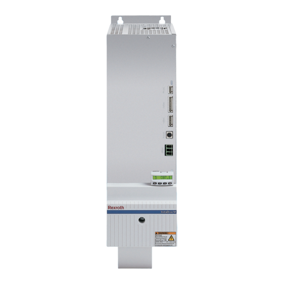
Box with Project Planning Manuals on Rexroth IndraDrive............. 1-4 Standards ..........................1-4 Your Feedback ........................1-4 Overview and Contents of the Documentations on the Drive System Rexroth IndraDrive ..1-5 Introducing the System ......................... 1-7 Drive System Rexroth IndraDrive C ..................1-7 Drive System Rexroth IndraDrive M .................. - Page 4 Configuration of the Drive System Rexroth IndraDrive Allowed Combination of Individual Components in Drive System Rexroth IndraDrive ....6-1 Allowed Combination of Range Components from IndraDrive M and IndraDrive C ....6-1 Allowed Combinations with Additional Components ............... 6-1 DOK-INDRV*-SYSTEM*****-PR02-EN-P...
- Page 5 Combinations of Firmware, Control Section and Drive Controller..........6-19 Combination with Other Rexroth Components ................6-21 Combination with Components of the Control Range Rexroth IndraControl V ..... 6-21 Combinations with Components of the Drive Range Diax04 ..........6-21 Selecting Connection Cables to Motor ..................6-22 Using Third-Party Motors in Drive System Rexroth IndraDrive ..........
- Page 6 Contents Rexroth IndraDrive Selecting the Mains Filter ......................8-6 Protecting Mains Filters Against Overload ................8-7 Limit Value Classes to be Achieved with Mains Filters ..............8-9 Mains Filters for Supply Modules HMV01.1E and HMV01.1R with HMS01/ HMD01 ..... 8-9 Mains Filters for Drive Controllers HCS02 ................
- Page 7 11.1 Control Circuits for the Mains Connection – General Information ..........11-1 Possibilities of Control ......................11-1 11.2 Control Circuits for Mains Connection of Drive Controllers Rexroth IndraDrive C ..... 11-3 Control via External Mains Contactor - HCS02 and HCS03 ..........11-3 Control Circuits HCS02 with DC Bus Resistor Unit HLB01.1C ..........
- Page 8 Contents Rexroth IndraDrive 14.5 Capacitor HAS04 ........................14-49 Type Code ........................... 14-49 Applications ......................... 14-49 Scope of Supply........................14-50 Capacitor ..........................14-51 Mounting the HAS04 Accessories ..................14-52 14.6 Accessories HAS05.1 ....................... 14-53 Type Code HAS05.1......................14-53 Applications ......................... 14-54 Scope of Supply........................
- Page 9 Rexroth IndraDrive Contents 16.1 General Information ........................16-1 16.2 How to Proceed When Replacing Devices................. 16-1 Replacing the Drive Controller....................16-1 Replacing the Motor ......................16-2 Replacing Cables ........................16-3 16.3 Fault Report ..........................16-4 17 Disposal and Environmental Protection 17-1 17.1 Disposal ............................
- Page 10 VIII Contents Rexroth IndraDrive DOK-INDRV*-SYSTEM*****-PR02-EN-P...
-
Page 11: Introduction
WARNING documentations into account. This documentation provides... Purpose of Documentation • overview information on the drive system Rexroth IndraDrive • a presentation of the documentations on the drive system Rexroth IndraDrive • help for selecting the system components of the drive system... - Page 12 Introduction Rexroth IndraDrive This documentation contains safety regulations, technical data and operating instructions for the drive system Rexroth IndraDrive. The individual chapters have the following main focuses: Main Focuses of the Chapters Chapter Title Content Introduction general information Important directions for use...
-
Page 13: Reference Documentations - Overview
Project Planning Manual DOK-INDRV*-HMV-*******-PRxx-EN-P Supply Units HMV01 Rexroth IndraDrive M Project Planning Manual DOK-INDRV*-HMS+HMD****-PRxx-EN-P Drive Controllers Power Sections HMx Rexroth IndraDrive C Project Planning Manual DOK-INDRV*-HCS02.1****-PRxx-EN-P Drive Controllers Power Sections HCS02.1 Rexroth IndraDrive C Project Planning Manual DOK-INDRV*-HCS03.1****-PRxx-EN-P Drive Controllers Power Sections HCS03.1... -
Page 14: Box With Project Planning Manuals On Rexroth Indradrive
German, European and international technical standards are mentioned in this documentation. Standard documents and sheets are subject to copyright protection and Rexroth mustn't pass them on. If required, contact the authorized sales agencies; in Germany directly contact: BEUTH Verlag GmbH... -
Page 15: Overview And Contents Of The Documentations On The Drive System Rexroth Indradrive
Overview and Contents of the Documentations on the Drive System Rexroth IndraDrive The drive system is composed of the individual components of the Rexroth IndraDrive Platform IndraDrive product range and established on the Rexroth IndraDrive platform. drive system control sections... - Page 16 Proj.Pl.Man. HMV Proj.Pl.Man. Proj.Pl.Man. Functional~ Proj.Pl.Man. HCS03 Parameter~ Proj.Pl.Man. HM* Troubleshooting Rexroth IndraDrive platform Fig. 1-5: Docu house Contents of Project Planning Contents of the Project Planning Manuals of components are all technical Manuals on Components data, such as •...
-
Page 17: Introducing The System
Rexroth IndraDrive Introduction Introducing the System The drive system Rexroth IndraDrive comprises all components from Drive System, Definition of Term mains supply to motor shaft. It consists of the components supply module with mains connection phase, power section with control section incl. -
Page 18: Drive System Rexroth Indradrive M
EMC requirements Fig. 1-7: Drive system Rexroth IndraDrive M System Elements - Components of the System The drive system Rexroth IndraDrive consists of the following system elements: System Types Characteristic... - Page 19 322 HLC01.1D output filter n.s. n.s. motor cable shielded motor rotary motors MSK, MBS, MBA etc. linear motors encoder cable n.s. accessories basic accessories HAS01.1 other accessories HAS02, HAS03 etc. Fig. 1-8: System elements Rexroth IndraDrive DOK-INDRV*-SYSTEM*****-PR02-EN-P...
-
Page 20: Differences Between Rexroth Indradrive C And Rexroth Indradrive M
Introduction Rexroth IndraDrive Differences between Rexroth IndraDrive C and Rexroth IndraDrive M The product ranges IndraDrive C and IndraDrive M were created on the IndraDrive platform. Rexroth IndraDrive C Rexroth IndraDrive C is the compact form of the product range. -
Page 21: Combination Of Rexroth Indradrive C And Rexroth Indradrive M
Combination of Rexroth IndraDrive C and Rexroth IndraDrive M On the common platform Rexroth IndraDrive it is possible to combine the components of the product ranges IndraDrive C and IndraDrive M to form drive systems of optimum costs and performance. For information on the allowed combinations see chapter. -
Page 22: Basic Design Of The Devices
1-12 Introduction Rexroth IndraDrive Basic Design of the Devices Basic Design of Drive Controllers lt_rtf2.fh7 power section control section Fig. 1-11: Basic design The drive controller consists of two essential parts: • power section • control section Power Section The power section incorporates the control section and has the following connections: •... - Page 23 1-13 Rexroth IndraDrive Introduction Control Section The control section is a separate component that is plugged into the power section; it consists of • the basic control section circuit board with interfaces • the optional modules in the case of configurable control sections The optional modules are included on the basic control section circuit board in optional slots.
-
Page 24: Available Type Currents And Performances
Available Type Currents and Performances To allow you selecting appropriate drive controllers for a multitude of applications the Rexroth IndraDrive product range provides a wide range of type currents and performances. The table below shows fundamental data of drive controllers and supply modules, for further details see the corresponding data sheets. -
Page 25: Selecting The Component For Mains Supply
1-15 Rexroth IndraDrive Introduction Selecting the Component for Mains Supply Order with ascending continuous power. Compact Modular Type Contin. Peak Contin. Max. converters mains current or power power braking braking supply power "ON" "ON" power power DC_cont DC_peak [kW] (1) - Page 26 1-16 Introduction Rexroth IndraDrive Notes DOK-INDRV*-SYSTEM*****-PR02-EN-P...
-
Page 27: Important Directions For Use
The user alone carries all responsibility of the risks. Before using Rexroth products, make sure that all the pre-requisites for an appropriate use of the products are satisfied: • Personnel that in any way, shape or form uses our products must first read and understand the relevant safety instructions and be familiar with appropriate use. -
Page 28: Areas Of Use And Application
Important Directions for Use Rexroth IndraDrive Areas of Use and Application Drive controllers made by Bosch Rexroth are designed to control electrical motors and monitor their operation. Control and monitoring of the motors may require additional sensors and actors. Note: The drive controllers may only be used with the accessories and parts specified in this document. -
Page 29: Safety Instructions For Electric Drives And Controls
Rexroth IndraDrive Safety Instructions for Electric Drives and Controls Safety Instructions for Electric Drives and Controls Introduction Read these instructions before the initial startup of the equipment in order to eliminate the risk of bodily harm or material damage. Follow these safety instructions at all times. -
Page 30: Hazards By Improper Use
Safety Instructions for Electric Drives and Controls Rexroth IndraDrive Hazards by Improper Use High voltage and high discharge current! Danger to life or severe bodily harm by electric shock! DANGER Dangerous movements! Danger to life, severe bodily harm or material damage by... -
Page 31: General Information
Rexroth IndraDrive Safety Instructions for Electric Drives and Controls General Information • Bosch Rexroth AG is not liable for damages resulting from failure to observe the warnings provided in this documentation. • Read the operating, maintenance and safety instructions in your language before starting up the machine. - Page 32 Safety Instructions for Electric Drives and Controls Rexroth IndraDrive • Operation is only permitted if the national EMC regulations for the application are met. The instructions for installation in accordance with EMC requirements can be found in the documentation "EMC in Drive and Control Systems".
-
Page 33: Protection Against Contact With Electrical Parts
Rexroth IndraDrive Safety Instructions for Electric Drives and Controls Protection Against Contact with Electrical Parts Note: This section refers to equipment and drive components with voltages above 50 Volts. Touching live parts with voltages of 50 Volts and more with bare hands or conductive tools or touching ungrounded housings can be dangerous and cause electric shock. -
Page 34: Protection Against Electric Shock By Protective Low Voltage (Pelv)
Protection Against Electric Shock by Protective Low Voltage (PELV) All connections and terminals with voltages between 0 and 50 Volts on Rexroth products are protective low voltages designed in accordance with international standards on electrical safety. High electrical voltage due to wrong... -
Page 35: Protection Against Dangerous Movements
Rexroth IndraDrive Safety Instructions for Electric Drives and Controls Protection Against Dangerous Movements Dangerous movements can be caused by faulty control of the connected motors. Some common examples are: • improper or wrong wiring of cable connections • incorrect operation of the equipment components •... - Page 36 Safety Instructions for Electric Drives and Controls Rexroth IndraDrive Dangerous movements! Danger to life, risk of injury, severe bodily harm or material damage! Ensure personal safety by means of qualified and ⇒ tested higher-level monitoring devices or measures DANGER integrated in the installation. Unintended machine motion is possible if monitoring devices are disabled, bypassed or not activated.
-
Page 37: Protection Against Magnetic And Electromagnetic Fields During Operation And Mounting
Rexroth IndraDrive Safety Instructions for Electric Drives and Controls ⇒ Disconnect electrical power to the equipment using a master switch and secure the switch against reconnection for: - maintenance and repair work - cleaning of equipment - long periods of discontinued equipment use ⇒... -
Page 38: Protection Against Contact With Hot Parts
3-10 Safety Instructions for Electric Drives and Controls Rexroth IndraDrive Protection Against Contact with Hot Parts Housing surfaces could be extremely hot! Danger of injury! Danger of burns! ⇒ Do not touch housing surfaces near sources of heat! Danger of burns! -
Page 39: 3.11 Battery Safety
3-11 Rexroth IndraDrive Safety Instructions for Electric Drives and Controls 3.11 Battery Safety Batteries contain reactive chemicals in a solid housing. Inappropriate handling may result in injuries or material damage. Risk of injury by incorrect handling! ⇒ Do not attempt to reactivate discharged batteries by heating or other methods (danger of explosion and cauterization). - Page 40 3-12 Safety Instructions for Electric Drives and Controls Rexroth IndraDrive Notes DOK-INDRV*-SYSTEM*****-PR02-EN-P...
-
Page 41: Brief Description, Applications
Applications of the Drive System Rexroth IndraDrive The digital intelligent automation system Rexroth IndraDrive is the cost- efficient solution with a high degree of functionality for single-axis and multi-axis drive and control tasks. -
Page 42: Mains Filters Hnf, Hnk, Nfe And Nfd
Brief Description, Applications Rexroth IndraDrive Mains Filters HNF, HNK, NFE and NFD Applications Mains filters are used to • reduce radio interference • reduce mains pollution The different mains filters can be used as follows: Device type Application NFE01.1 mains filter for interference suppression of supply units up to 230 V NFE02.1... -
Page 43: Supply Units Hmv01
Rexroth IndraDrive Brief Description, Applications Supply Units HMV01 Applications HMV supply modules are used to • supply modular devices HMS and HMD The different supply modules can be used as follows: Device type Application HMV01.1E infeeding The HMV01.1E supply modules are used to supply drive controllers HMS01 and HMD01. -
Page 44: Control Sections Csh01, Csb01, Cdb01
Brief Description, Applications Rexroth IndraDrive Control Sections CSH01, CSB01, CDB01 Applications Control sections CSH, CSB and CDB are used to • operate drive controllers HMS, HMD and HCS The different control sections can be used as follows: Device type Application... -
Page 45: Dc Bus Resistor Unit Hlb01
Applications HLB01.1C HLB01.1C DC bus resistor units - are used in drive systems with components of the product range Rexroth IndraDrive C. HLB01.1D HLB01.1D DC bus resistor units - are used in drive systems with components of the product range Rexroth IndraDrive M. -
Page 46: 4.10 Braking Resistor Hlr01
Application HLC01.1C DC bus capacitor units HLC01.1C - are used in drive systems of the product ranges Rexroth IndraDrive C and M. HLC01.1D DC bus capacitor units HLC01.1D - are used in drive systems of the product ranges Rexroth IndraDrive C and M. -
Page 47: 4.12 Motor Filters Hmf01
Motor filter HMF01 applications 4.13 Accessories HAS Applications HAS accessories are used to support the operation and combination of components in the drive system Rexroth IndraDrive. The different accessories and their use are described in chapter "Accessories". 4.14 Accessory HAC01... - Page 48 Brief Description, Applications Rexroth IndraDrive Notes DOK-INDRV*-SYSTEM*****-PR02-EN-P...
-
Page 49: Specifications For The Components Of The Drive System
• C-UL-US Listing according to UL 508 C The devices are listed under the term "Rexroth". Note: For using the devices in the scope of C-UL, take the C-UL limit values of the individual devices into account. In addition, take the following aspects into account: •... - Page 50 Specifications for the Components of the Drive System Rexroth IndraDrive Tests high-voltage test routine test according to EN50178 high voltage and insulation test routine test according to EN50178 separation between control and safe separation according to power voltage circuits EN50178...
-
Page 51: Transport And Storage
Rexroth IndraDrive Specifications for the Components of the Drive System Transport and Storage Transport of the Devices Conditions temperature -25 ... 70 °C relative humidity 5 ... 95%; climatic category 2K3 absolute humidity 1 ... 60 g/m climatic category 2K3... -
Page 52: Installation Conditions
Specifications for the Components of the Drive System Rexroth IndraDrive Installation Conditions Ambient and Operating Conditions The drive controllers and their additional components are designed for control cabinet mounting! Note: The user must check that the ambient conditions, in particular... -
Page 53: Capacity Utilization
Rexroth IndraDrive Specifications for the Components of the Drive System All Rexroth controls and drives are developed and tested according to the Compatibility with Foreign Matters state-of-the-art technology. As it is impossible to follow the continuing development of all materials (e.g. - Page 54 Specifications for the Components of the Drive System Rexroth IndraDrive 1000 2000 3000 4000 Installation altitude above sea level in meters DK000074v01_en Fig. 5-8: Capacity utilization at higher installation altitude DOK-INDRV*-SYSTEM*****-PR02-EN-P...
-
Page 55: Supply Voltages
Rexroth IndraDrive Specifications for the Components of the Drive System Supply Voltages Control Voltage 24V Supply For the devices of the IndraDrive range, the specifications for supply with control voltage contained in the table below are generally valid. Standard range and extended range of control voltage... -
Page 56: Power Voltage Supply
Specifications for the Components of the Drive System Rexroth IndraDrive Power Voltage Supply For the devices of the IndraDrive range, the specifications for supply with power voltage contained in the table below are generally valid. The indicated values represent the common standard range. -
Page 57: Limited Length Of Motor Power Cables
Rexroth IndraDrive Specifications for the Components of the Drive System Limited Length of Motor Power Cables The restrictions contained in the table below apply to the components HCS, HMS, HMD. To avoid overload of the drive controller the motor cable length is limited Data of Motor Power Cable depending on the switching frequency. - Page 58 5-10 Specifications for the Components of the Drive System Rexroth IndraDrive Notes DOK-INDRV*-SYSTEM*****-PR02-EN-P...
-
Page 59: Configuration Of The Drive System Rexroth Indradrive
Configuration of the Drive System Rexroth IndraDrive Configuration of the Drive System Rexroth IndraDrive Allowed Combination of Individual Components in Drive System Rexroth IndraDrive Within the product range Rexroth IndraDrive you may combine components subranges Rexroth IndraDrive C Rexroth IndraDrive M. -
Page 60: Allowed Components In Mains Connection Phase
Configuration of the Drive System Rexroth IndraDrive Rexroth IndraDrive Allowed Components in Mains Connection Phase Note: Operating supply units with regeneration back to the mains requires components appropriate for this purpose in the mains connection phase. Make sure the type code sections -R or -E are matching. - Page 61 Rexroth IndraDrive Configuration of the Drive System Rexroth IndraDrive Drive controller / Capacitance Additional capacitances against supply unit against housing ground required? [ nF ] HAS04 2 * 470 HMV01.1E 2 * 470 HMV01.1R 2 * 470 Fig. 6-4: Capacitances at L+ und L- The requirement of minimum capacitance is, for example, •...
-
Page 62: Combination Hmv01 With Hms/Hmd (Rexroth Indradrive M)
W0054 up to max. W0036 into DCext account HMV01.1R-W0045 up to max. W0150 up to max. W0036 HMV01.1R-W0065 up to max. W0210 up to max. W0036 Fig. 6-6: Allowed Rexroth IndraDrive M components at common DC bus DOK-INDRV*-SYSTEM*****-PR02-EN-P... - Page 63 Rexroth IndraDrive Configuration of the Drive System Rexroth IndraDrive Note: Take the maximum allowed peak power and continuous power data of the supply unit into account. Depending on the mains filter used and the mains choke, the number of axes is additionally restricted.
-
Page 64: Combination Hcs02 With Hcs02 (Rexroth Indradrive C)
Note: At the common DC bus means that the DC bus connections of the involved devices are interconnected. Type of mains connect. (1) Maximum number of IndraDrive C components at common DC bus HCS02.1E- HLB01.1 HLC01.1 group supply with DC bus... - Page 65 HCS02 to charge Y-capacitors. You may make replacements up to the maximum allowed sum of the type currents. Maximum number of IndraDrive C components at common DC bus (plus Type of mains connect. (1) supplying device in the case of central supply) max.
-
Page 66: Combination Hcs03 With Hcs03 (Rexroth Indradrive C)
Operating HAS accessories with capacitances against housing is allowed. Group Supply with DC Bus Connection HCS03 (Parallel Operation) Type of mains connect. (1) Maximum number of IndraDrive C components at common DC bus HCS03.1E- HLB01.1 HLC01.1 group supply with DC bus... -
Page 67: Combination Hcs02 With Hms / Hmd (Rexroth Indradrive C With Rexroth Indradrive M)
Rexroth IndraDrive Configuration of the Drive System Rexroth IndraDrive Combination HCS02 with HMS / HMD (Rexroth IndraDrive C with Rexroth IndraDrive M) Combining HCS02 drive controllers with HMS / HMD requires using • accessory HAS04 (capacitances at DC bus against ground) •... - Page 68 6-10 Configuration of the Drive System Rexroth IndraDrive Rexroth IndraDrive Example central supply via HCS02.1E-W0070 with assigned HNL01.1 mains choke: • 1 * HCS02.1E-W0070 (supplying device) • 1 * HMS01.1N-W0054 • 1 * HMS01.1N-W0036 • 1 * HMS01.1N-W0020 • 1 * HMD01.1N-W0036 •...
-
Page 69: Combination Hcs03 With Hms / Hmd
6-11 Rexroth IndraDrive Configuration of the Drive System Rexroth IndraDrive Combination HCS03 with HMS / HMD Note: For combinations HCS03 with HMD01 and HMS01 we recommend using brake chopper and braking resistor. Using external DC bus capacitances C is not required. -
Page 70: Combinations At Common Dc Bus That Are Not Allowed
Operating the following combinations at the common DC bus is not allowed • HCS02 with HMV • HCS03 with HMV • HCS02 with HCS03 Note: Operating components not mentioned in this documentation at the common DC bus with Rexroth IndraDrive components requires Rexroth's explicit confirmation. DOK-INDRV*-SYSTEM*****-PR02-EN-P... -
Page 71: Allowed Combinations In Mains Connection Phase With Mains Chokes Hnl, Mains Filters Hnf And Mains Chokes Hnk
Allowed Combinations in Mains Connection Phase with Mains Chokes HNL, Mains Filters HNF and Mains Chokes The modular structure of the Rexroth IndraDrive system allows a multitude of combinations for mains connection. The combinations of mains filters and mains chokes listed below are functionally allowed in the mains connection phase. -
Page 72: Mains Connection Phase For Hcs With Mains Chokes Hnl And Mains Filters Hnf Resp. Nfd
6-14 Configuration of the Drive System Rexroth IndraDrive Rexroth IndraDrive HMV01.1R Supply Units Supply unit Mains chokes Mains filters Explanation HMV01.1R-W0018 HNL01.1R-0980-C0026 HNF01.1A-F240-R0026 standard combination without HNF01.1A-F240-R0026 not allowed HNL01.1R-0980-C0026 HNF01.1A-M900-R0026 standard combination without HNF01.1A-M900-R0026 not allowed HNL01.1R-0980-C0026 with customer-side standard mains choke connected in HNL01.1R-4200-S0026... - Page 73 6-15 Rexroth IndraDrive Configuration of the Drive System Rexroth IndraDrive Note: For operation without mains choke take reduced performance data of the supply units or HCS into account. Observe performance data contained in the respective Project Planning Manual! HCS02 Drive Controllers...
- Page 74 6-16 Configuration of the Drive System Rexroth IndraDrive Rexroth IndraDrive HCS03 Drive Controllers Supply unit Mains chokes Mains filters Explanation integrated in HNK HNK01.1A-A075-E0050 standard for operating one drive controller at the mains filter HNL01.1E-0571-N0050 standard for operating one drive...
- Page 75 6-17 Rexroth IndraDrive Configuration of the Drive System Rexroth IndraDrive Supply unit Mains chokes Mains filters Explanation integrated in HNK HNK01.1A-A075-E0106 standard for operating one drive controller at the mains filter HNL01.1E-0240-N0106 without standard for operating one drive controller without mains filter without HNF01.1A-F240-E0125...
-
Page 76: Allowed Combinations With Motor Filters Hmf01
6-18 Configuration of the Drive System Rexroth IndraDrive Rexroth IndraDrive Allowed Combinations with Motor Filters HMF01 In conjunction with long motor cables, the steep switching edges at the motor output of the drive controllers cause transient overvoltages and high rise of voltage at the motor. -
Page 77: Combinations Of Firmware, Control Section And Drive Controller
The modular structure of the IndraDrive controllers allows a multitude of combinations of control sections and drive controllers. Depending on the firmware design, the firmware of the Rexroth IndraDrive product range supports the combinations of control section and power section listed below. - Page 78 Rexroth IndraDrive Required Equipment of Control Section for Motor Encoder System The control sections of the Rexroth IndraDrive product range support different encoder systems. For the assignment of encoder system to required equipment of control section with options see table below.
-
Page 79: Combination With Other Rexroth Components
Combination with Components of the Control Range Rexroth IndraControl V Small Operator Terminals VCP For comfortable operation of the Rexroth IndraDrive drive system with the IndraControl V control range there are small operator terminals of the VCP series available. The small operator terminals VCP 01, VCP 02, VCP 05, VCP 08, VCP 20 and VCP 25 are suited for control cabinet mounting and are operated via the serial interface RS232 (X2) of the control sections. -
Page 80: Selecting Connection Cables To Motor
The documentation "Rexroth Connection Cables; Selection Data" is available for selecting the motor power cables and other connections, such as encoder cables. Rexroth IndraDrive drive systems have to be equipped with shielded motor power cables of the RKL line. Requirements on third-party motor power cables:... -
Page 81: Arranging The Components In The Control Cabinet
G1: Normal mounting position. The natural convection supports the forced cooling air current. This avoids the generation of pockets of heat in the drive controller. G1 is the preferred mounting position for Rexroth IndraDrive components. • G2: 180° to normal mounting position •... - Page 82 Arranging the Components in the Control Cabinet Rexroth IndraDrive Allowed positions of normal use and mounting positions with reduction factor Component Mounting position / reduction factor Notes HCS02.1E 100% HCS03.1E 100% HMV01.1E 100% HMV01.1R 100% HMS01.1 100% HMD01.1 100% reduction of maximum allowed...
-
Page 83: Main Dimensions Of The System Components
Rexroth IndraDrive Arranging the Components in the Control Cabinet Main Dimensions of the System Components The main differences in the dimensions of the individual products of the range are contained in the figure and table below. Note: The mounting depths of the IndraDrive product range have been optimized for mounting in control cabinets with 300 mm or 400 mm. - Page 84 Arranging the Components in the Control Cabinet Rexroth IndraDrive Device Depths, Heights and Widths Min. moun- Device Device ting Device width C width height Device depth [mm] [mm] 1) [mm] 2) [mm] 3) HLC01.1C-01M0 HLC01.1C-02M4 HCS02.1E-W0012 for control cabinets with HCS02.1E-W0028...
-
Page 85: Distances For Drive Controllers
Rexroth IndraDrive Arranging the Components in the Control Cabinet Distances for Drive Controllers In addition to the mounting dimensions, the components of the Rexroth IndraDrive range require additional mounting clearance • to ventilate the components • to mount accessories and connections •... - Page 86 Arranging the Components in the Control Cabinet Rexroth IndraDrive Distances on Top and Bottom of Components Owing to power dissipation in the components, the temperature of the cooling air current at the device outlet is rising to values higher than ambient temperature at device inlet.
- Page 87 Rexroth IndraDrive Arranging the Components in the Control Cabinet The minimum distance for ventilation does not take the additional Minimum Distance to Mounting Parts dimensions of accessories (e.g. HAS02) into account; for these dimensions see the dimension sheets. For components with integrated braking resistor (supply modules, DC bus...
- Page 88 Arranging the Components in the Control Cabinet Rexroth IndraDrive bleeder_abstand.fh7 Fig. 7-8: Minimum distance at HMV supply units DOK-INDRV*-SYSTEM*****-PR02-EN-P...
-
Page 89: Boring Dimensions For The Mounting Plate
Rexroth IndraDrive Arranging the Components in the Control Cabinet Boring Dimensions for the Mounting Plate Individually Arranged Drive Controllers HNF_bohrbild.fh7 HNF_bohrbild.EPS Fig. 7-9: Boring dimensions Note: The figure shows the back of the devices. DOK-INDRV*-SYSTEM*****-PR02-EN-P... - Page 90 7-10 Arranging the Components in the Control Cabinet Rexroth IndraDrive Device Notes [mm] [mm] [mm] [mm] [mm] observe additional distance to lateral HCS02.1E-W0012 32,5 neighboring devices observe additional distance to lateral HCS02.1E-W0028 32,5 neighboring devices observe additional distance to lateral HCS02.1E-W0054...
- Page 91 Rexroth IndraDrive M components Note: prevailing grid fixing bores within Rexroth IndraDrive M product range is 25 mm. For performance-dependent arrangement of the components see Rexroth IndraDrive M Fig. 7-20: Example arrangement. The HAS02 accessories in the figure require additional mounting clearance. DOK-INDRV*-SYSTEM*****-PR02-EN-P...
- Page 92 7-12 Arranging the Components in the Control Cabinet Rexroth IndraDrive Dimension Z is significantly determined by the involved components. The table below contains the dimensions Z between the component arranged to the left and the component arranged to the right.
- Page 93 7-13 Rexroth IndraDrive Arranging the Components in the Control Cabinet Dimension Z Component left Component right [mm] HMV01.1E-W0030 HMV01.1E-W0075 HMV01.1E-W0120 HMV01.1R-W0018 HMV01.1R-W0045 HMV01.1R-W0065 HMS01.1N-W0020 HLC01.1C-01M0 HMS01.1N-W0036 57,5 HLC01.1C-02M4 HMS01.1N-W0070 HMS01.1N-W0150 HMS01.1N-W0210 HMD01.1N-W0012 HMD01.1N-W0020 HLC01.1D-05M0 HLB01.1D HLC01.1C-01M0 HLC01.1C-01M0 HLC01.1C-02M4 HLC01.1C-02M4 Fig. 7-12:...
- Page 94 Observe that using HAS04 accessory at the HCS02 arranged at the utmost left position requires another 30 mm. Rexroth IndraDrive components are arranged in line to the right starting from the supplying device. Arrange the drive controllers with high capacity as close to the supplying unit as possible.
- Page 95 7-15 Rexroth IndraDrive Arranging the Components in the Control Cabinet Dimension Z is significantly determined by the involved components. The table below contains the dimensions Z between the component arranged to the left and the component arranged to the right.
- Page 96 Observe that using HAS04 accessory at the HCS02 arranged at the utmost left position requires another 25 mm. Rexroth IndraDrive M components are arranged in line to the right starting from the supplying drive controller HCS. Dimension Z is significantly determined by the involved components. The table below contains the dimensions Z between the component arranged to the left and the component arranged to the right.
-
Page 97: Arranging Components In Control Cabinet From Mainly Thermal Point Of View
7-17 Rexroth IndraDrive Arranging the Components in the Control Cabinet Arranging Components in Control Cabinet from Mainly Thermal Point of View Multiple-Line Arrangement of Drive Controllers Control Cabinet with Multiple-Line Structure Note: Particular attention should be paid to the maximum allowed air intake temperature of components when they are arranged in multiple lines in the control cabinet. -
Page 98: Arrangement Of Cooling Units
7-18 Arranging the Components in the Control Cabinet Rexroth IndraDrive Arrangement of Cooling Units Possible damage to the drive controller Operational safety of the machine endangered Note the following instructions CAUTION Avoiding Dripping or Sprayed Due to the operating principle, condensation water is formed when cooling Water units are used. - Page 99 7-19 Rexroth IndraDrive Arranging the Components in the Control Cabinet incorrect correct control cabinet control cabinet air intake air intake air outlet duct cooling cooling unit unit electronic electronic equipment equipment Eb0002f1.fh7 Fig. 7-19: Arranging the cooling unit at the front of the control cabinet...
-
Page 100: Arranging Components In Control Cabinet From Mainly Electrical Point Of View
7-20 Arranging the Components in the Control Cabinet Rexroth IndraDrive Arranging Components in Control Cabinet from Mainly Electrical Point of View The section below contains information and recommendations on the arrangement of the components in the control cabinet from mainly electrical points of view. -
Page 101: Emc Measures For Design And Installation
Drive Controller them. Installation of Motor Power Preferably use the motor power cables with shield provided by Rexroth. If Cable you use other motor power cables, they have to be run in shielded form. Keep length of motor power cable as short as possible. -
Page 102: Emc-Optimal Installation In Facility And Control Cabinet
7-22 Arranging the Components in the Control Cabinet Rexroth IndraDrive Do not use any steel-shielded lines. The shield of the motor cable mustn't be interrupted by mounted components, such as output chokes, sine filters, motor filters. EMC-Optimal Installation in Facility and Control Cabinet... - Page 103 7-23 Rexroth IndraDrive Arranging the Components in the Control Cabinet area A area B area C signal lines control cabinet probes reference cams distance to bus cables motor power cable d5 = min. 100 mm LINE fuses drives auxiliary or...
- Page 104 7-24 Arranging the Components in the Control Cabinet Rexroth IndraDrive Design and Installation in Interference-Free Area of Control Cabinet (Area A) When arranging the components in the control cabinet, make sure that Arranging the Components in the Control Cabinet the components and electrical elements (switches, pushbuttons, fuses,...
- Page 105 7-25 Rexroth IndraDrive Arranging the Components in the Control Cabinet If there is a high degree of interference injection to the power input line Shielding Mains Supply Lines in Control Cabinet within the control cabinet, in spite of you having observed the above instructions (to be found out by standard EMC measurement), the lines in area A have to be routed in shielded form.
- Page 106 7-26 Arranging the Components in the Control Cabinet Rexroth IndraDrive Run the lines along grounded metal surfaces, in order to minimize Line Routing radiation of interference fields to area A (transmitting antenna effect). Design and Installation in Strongly Interference- Susceptible Area of Control Cabinet (Area C) Area C mainly concerns the motor cables.
- Page 107 7-27 Rexroth IndraDrive Arranging the Components in the Control Cabinet Area B drive controllers Area C parallel routing: length max. 300 mm cable duct 1: mains connection lines cable duct 2: motor cable motor cable: shield contact via clips at least at one...
-
Page 108: Connection Of Motor Cable To Drive Controller
7-28 Arranging the Components in the Control Cabinet Rexroth IndraDrive Connection of Motor Cable to Drive Controller There are the following minimum requirements for connecting the motor cables to the drive controller: • Connect the shield of the motor cable over the largest possible surface area (with low impedance) to the drive controller. - Page 109 • With a cable (6) (line cross section at least 10 mm2) connect ground bus (4) to ground connection at supplying device (Rexroth IndraDrive supply unit or Rexroth IndraDrive drive controller HCS). Connect cable shield to a ground bus. The cable length between device Alternative 2 and ground bus mustn't be more than a max.
- Page 110 10 mm2. • With a cable (6) (line cross section at least 10 mm2) connect ground bus (4) to ground connection at supplying device (Rexroth IndraDrive supply unit or Rexroth IndraDrive drive controller HCS). • Make sure there is sufficient strain relief for the motor power cable as near as possible to the drive-side cable end (7).
- Page 111 7-31 Rexroth IndraDrive Arranging the Components in the Control Cabinet Note: Do not remove the shield of the motor cable between ground bus and device. If the motor cables are routed to the control cabinet via flange boxes, the shield is directly connected to the wall of the control cabinet over a large surface area via the housing of the flange box.
-
Page 112: Ground Connections
7-32 Arranging the Components in the Control Cabinet Rexroth IndraDrive Ground Connections Housing and Mounting Plate By means of appropriate ground connections it is possible to avoid the emission of interference, because interference is discharged to earth on the shortest possible way. Ground connection of the metal housings of... -
Page 113: Installing Signal Lines And Cables
7-33 Rexroth IndraDrive Arranging the Components in the Control Cabinet Installing Signal Lines and Cables For measures to prevent interference see the Project Planning Manuals Line Routing respective device. addition, observe following recommendations: Signal and control lines have to be routed separately from the power cables with a minimum distance of d5 = 100 mm (see Fig. -
Page 114: Installing The 24V Supply
Installing the 24V Supply As a matter of principle, the 24V supply of the components of the drive system Rexroth IndraDrive has to be installed in star-shaped form, i.e. for each group of drive controllers or third-party components it is necessary to run separate supply lines. -
Page 115: General Measures Of Radio Interference Suppression For Relays, Contactors, Switches, Chokes, Inductive Loads
7-35 Rexroth IndraDrive Arranging the Components in the Control Cabinet General Measures of Radio Interference Suppression for Relays, Contactors, Switches, Chokes, Inductive Loads If, in conjunction with electronic devices and components, inductive loads, such as chokes, contactors, relays are switched by contacts or semiconductors, appropriate interference suppression has to be provided for them. - Page 116 7-36 Arranging the Components in the Control Cabinet Rexroth IndraDrive Notes DOK-INDRV*-SYSTEM*****-PR02-EN-P...
-
Page 117: Electromagnetic Compatibility (Emc)
1992-11-09. EMC Properties of Components Drive and control components by Rexroth are designed and built, in accordance with the present state-of-the-art of standardization, according to legal regulations of the EU directive 89/336/EWG and the German EMC law. -
Page 118: Noise Immunity In Drive System
Electromagnetic Compatibility (EMC) Rexroth IndraDrive Noise Immunity in Drive System The figure below illustrates the interfaces for definition of noise immunity requirements in the drive system. enclosure port 1 drive system/ machine Application Examples: enclosure port 2 • unit SERCOSinterface •... -
Page 119: Noise Emission Of Drive System
Rexroth IndraDrive Electromagnetic Compatibility (EMC) No Place of effect Pheno- Standard Conditions Coupling Test values Perfor- menom according mance standard EN level 61800-3 Signal Interface Burst IEC 61000-4-4 length > 3 m clamp IEC 61000-4-6 length > 3 m Clamp or CDN 10 V, 0,15 –... - Page 120 Electromagnetic Compatibility (EMC) Rexroth IndraDrive Limit Values for Line-Based Disturbances According to IEC EN 61800-3 or CISPR 11, the limit values in the table below are distinguished. For this documentation both standards are combined in the limit value classes A2.1 to B1.
- Page 121 EN 61800-3/ A11, section 6.3 has to be observed. Note: Components of the drive system Rexroth IndraDrive are products of restricted distribution according to IEC61800-3! In residential areas these products can cause radio interference.
-
Page 122: Selecting The Mains Filter
2. Check or determine max. occurring ambient temperature. 3. Determine max. applied mains voltage. Observe that not all Rexroth IndraDrive mains filters are suited for mains voltage of 3AC500V. 4. Determine kind of mains connection, such as central supply, group supply etc. -
Page 123: Protecting Mains Filters Against Overload
Within a mains filter line you can replace mains filters of lower type current by such ones with higher type current. For Rexroth drive systems there are the following mains filters for radio interference suppression available: • NFE01.1, NFE02.1, NFD03.1, HNF01.1, HNK01.1 These filters have been especially dimensioned for Rexroth drive systems. - Page 124 Electromagnetic Compatibility (EMC) Rexroth IndraDrive To connect the shield at the motor, a suitable PG gland with shield connection can be used (e.g. "SKINDICHT SHV/SRE/E" from the Lapp Company, Stuttgart). Make sure that the connection between the motor terminal box and the motor housing has a low impedance. If necessary, use an additional grounding strap between them.
-
Page 125: Limit Value Classes To Be Achieved With Mains Filters
Rexroth IndraDrive Electromagnetic Compatibility (EMC) Limit Value Classes to be Achieved with Mains Filters For explanations on the dimensioning criterion limit value class see chapter 8.3 "Noise Emission of Drive System" under "Limit Values for Line-Based Disturbances". calculation formulas determining... - Page 126 8-10 Electromagnetic Compatibility (EMC) Rexroth IndraDrive Limit Value Classes for HMV01.1R Supply Modules Note: Damage caused by missing mains choke! Always operate HMV01.1R supply units with the assigned mains choke HNL01.1R. Supply unit type Mains filter type Max. allowed Max. allowed...
-
Page 127: Mains Filters For Drive Controllers Hcs02
8-11 Rexroth IndraDrive Electromagnetic Compatibility (EMC) Mains Filters for Drive Controllers HCS02 Note: With HCS02.1E drive controllers the limit value class A2.1 (see 8.3 Noise Emission of Drive System) can already be achieved without mains filters. • Observe notes in chapter. - Page 128 8-12 Electromagnetic Compatibility (EMC) Rexroth IndraDrive Drive controller Mains filter type Max. Max. all. Max. all. Allowed leakage type allowed total frequ. leakage capacitance to comply number of length of [kHz] capac. 1) with limit value class drive contr. motor...
-
Page 129: Mains Filters For Drive Controllers Hcs03
8-13 Rexroth IndraDrive Electromagnetic Compatibility (EMC) Mains Filters for Drive Controllers HCS03 Note: At HCS03.1E drive controllers, do not operate any external additional capacitances at the DC bus. Exception: For drive controllers HCS03.1E-...-W0210 this is allowed. Limit Value Classes for HCS03 Drive Controllers with... - Page 130 8-14 Electromagnetic Compatibility (EMC) Rexroth IndraDrive Limit Value Classes for HCS03 Drive Controllers with HMS, HMD and HNF01 Drive Controllers Drive controller Mains filter type Max. Max. allowed Allowed leakage type allowed total length frequ. capacitance to comply number of...
-
Page 131: Types Of Mains Connection
Rexroth IndraDrive Types of Mains Connection Types of Mains Connection Drive systems with Rexroth IndraDrive controllers can be connected to the mains in different ways. We distinguish the following types of mains connection: • individual supply • group supply without DC bus DC bus connection •... -
Page 132: Individual Supply
Types of Mains Connection Rexroth IndraDrive Individual Supply The mains connection individual supply is the standard type of connection. It is characterized by one mains connection (mains circuit breaker, mains transformer, mains filter, mains choke) for each drive system. Individual Supply with HMV It is possible to connect further drive controllers and additional components to the supply module. - Page 133 Rexroth IndraDrive Types of Mains Connection Note: When using the component HCS03.1E with HNK01.1 connect the mains contactor electrically between the mains connection and the HNK. Note: DC bus connection of devices connected to the mains via different mains contactors is not allowed.
-
Page 134: Group Supply
Types of Mains Connection Rexroth IndraDrive Group Supply Group supply means that a component of the mains connection (mains circuit breaker, mains transformer, mains filter, mains choke) is used by several drive systems. Group Supply without DC Bus Connection of the Groups... - Page 135 Rexroth IndraDrive Types of Mains Connection Group Supply HMV without DC Bus Connection of the Groups Antriebsgruppe ohne Zwischenkreisverbindung HMV.EPS optionally required components are marked with gray background color Fig. 9-4: Group supply HMV without DC bus connection of the groups...
-
Page 136: Group Supply With Dc Bus Connection Of The Groups
Types of Mains Connection Rexroth IndraDrive Group Supply with DC Bus Connection of the Groups Group supply with DC bus connection increases the available regenerative power and continuous braking resistor power in the common DC bus of several drive controllers or drive systems. - Page 137 Rexroth IndraDrive Types of Mains Connection This type of mains connection is only allowed for HMV01.1E (not allowed Group Supply HMV with DC Bus Connection of the Groups for HMV01.1R). This mains connection is used for high-performance drive systems. Fuse...
-
Page 138: Central Supply
Central Supply HCS With the type of mains connection "central supply" the compact IndraDrive C line is similar to the modular IndraDrive M line. We speak of "central supply" when an HCS drive controller supplies other drive controllers HCS, HMS or HMD which are not connected to the mains. -
Page 139: Requirements To The Mains Connection
Requirements to the Mains Connection 10.1 General Information Note: A permanent connection to the supply mains is required for Rexroth IndraDrive controllers. 10.2 Mains Types The devices can be operated at the following mains systems. The requirements are indicated under the respective mains type. -
Page 140: It System
10-2 Requirements to the Mains Connection Rexroth IndraDrive IT System I = isolation of all active parts from ground or connection of one point to ground via an impedance T = exposed conductive parts directly grounded, independent of grounding of current source (station ground) Fig. -
Page 141: Mains With Grounded Outer Conductor (Corner Grounded Delta Mains)
10-3 Rexroth IndraDrive Requirements to the Mains Connection Mains with Grounded Outer Conductor (Corner Grounded Delta Mains) I = isolation of all active parts from ground, connection of one phase – generally phase v - to ground or via an impedance... - Page 142 10-4 Requirements to the Mains Connection Rexroth IndraDrive results in the case of a short circuit at the point of power supply connection. It is calculated as follows: system impedance mains voltage Fig. 10-7: Mains short-circuit current Mains Classes We basically distinguish the following mains, graded according to mains...
-
Page 143: Maximum Connected Load To A Mains
10-5 Rexroth IndraDrive Requirements to the Mains Connection Maximum Connected Load to a Mains The maximum connected load to a mains depends on the allowed distortion of the mains voltage due to the load current with harmonics (mains pollution). The distortion is described by the distortion factor or the total harmonic distortion (THD) of the mains current (see chapter "Calculations"). - Page 144 10-6 Requirements to the Mains Connection Rexroth IndraDrive Realizable Realizable Drive controller or supply Kind of drive distortion THD of mains unit with and without mains controller factor of current choke mains current HMV01.1E all devices THD>=50% K>=60% HCS03.1 without HCS02.1...
-
Page 145: 10.4 Limit Values For Interference-Free Operation At Mains
10-7 Rexroth IndraDrive Requirements to the Mains Connection Rsc=250 Rsc=200 Rsc=100 Rsc=50 Classification 800,00 1000,00 2000,00 4000,00 600,00 750,00 1500,00 3000,00 rigid mains 400,00 500,00 1000,00 2000,00 200,00 250,00 500,00 1000,00 160,00 200,00 400,00 800,00 120,00 150,00 300,00 600,00 80,00... -
Page 146: Commutation Drops
10-8 Requirements to the Mains Connection Rexroth IndraDrive Max. allowed voltage unbalance Standard reference IEC 61000-2-4, class 3 Fig. 10-14: Maximum allowed voltage unbalance Commutation Drops Drop on mains voltage Standard reference depth 40% of mains amplitude, total surface IEC 60146-1-1, class 3 250% x degrees (see diagram) Fig. -
Page 147: Maximum Allowed Mains Overvoltages
10-9 Rexroth IndraDrive Requirements to the Mains Connection Maximum Allowed Mains Overvoltages The devices were dimensioned only up to a certain level of mains over voltage. Higher overvoltage has to be limited by other measures, e.g. overvoltage protection on site. - Page 148 10-10 Requirements to the Mains Connection Rexroth IndraDrive The figure below illustrates the voltage pulse. DK000075v01_en.tif Fig. 10-19: Impulse withstand voltage 1,2/ 50µs and 8/ 20 µs according to EN 61000 If higher overvoltage values can occur in the application, measures for limitation of the values have to be taken in the electrical equipment of the machine or installation.
- Page 149 • due to inductive or capacitive coupling on lines. Use overvoltage limiters at the machine or installation when the overvoltage occurring at the Rexroth components is greater than the max. allowed overvoltage. Use the overvoltage limiters at long lines run through the building / the hall and run in parallel with power and mains cables.
-
Page 150: Power Factors And Emitted Mains Harmonics Of The Device
10-12 Requirements to the Mains Connection Rexroth IndraDrive 10.5 Power Factors and Emitted Mains Harmonics of the Device Due to their electric design, the drive controllers and supply units generate harmonics in the mains current and on the mains voltage during operation at the mains. -
Page 151: Harmonics Factors Thd And Distortion Factor K
10-13 Rexroth IndraDrive Requirements to the Mains Connection Harmonics Factors THD and Distortion Factor k The mains harmonics are decisively influenced by mains chokes. Type of drive controller Type of 3AC400V 3AC480V 3AC500V Notes or supply unit mains choke HCS02... -
Page 152: 10.6 Protection Systems For The Mains Connection
10-14 Requirements to the Mains Connection Rexroth IndraDrive These values, however, can temporally vary quite strongly, according to the switch status of the mains. The harmonics of the mains voltage thereby change, too. Rough estimated values of the mains data are not sufficient for pre- calculation of the harmonics, as mainly the resonance points always present in the mains have a strong influence on the harmonics content. - Page 153 10-15 Rexroth IndraDrive Requirements to the Mains Connection Fusing by Protective Grounding in TN-S Mains TN-S mains control cabinet HCS02 HCS02 HLB01. 1 HLB01. 1 HCS03 HLC01. 1 HCS03 HLC01. 1 error joint bar of equipment grounding conductors aim of protective measures: contact voltage < 50V at housing DC bus connection L+/L- DA000007_en.fh7...
- Page 154 10-16 Requirements to the Mains Connection Rexroth IndraDrive Fusing by Protective Grounding in TN-C Mains TN-C mains (grounded mains) control cabinet HCS02 HCS02 HLB01. 1 HLB01. 1 HCS03 HLC01. 1 HCS03 HLC01. 1 error joint bar of equipment grounding conductors aim of protective measures: contact voltage <...
- Page 155 10-17 Rexroth IndraDrive Requirements to the Mains Connection Fusing by Protective Grounding in IT Mains (Ungrounded Mains) IT mains (ungrounded mains) control cabinet HCS02 HCS02 HLB01. 1 HLB01. 1 HCS03 HLC01. 1 HCS03 HLC01. 1 error joint bar of equipment grounding conductors aim of protective measures: contact voltage <...
-
Page 156: Connecting Equipment Grounding Conductor
• RCM (Residual-Current Monitoring Device) Note: Rexroth IndraDrive drive systems can only be used with residual-current-operated circuit-breakers to a limited extent. If these circuit breakers are to be used, the company erecting the installation has to check the mutual compatibility of the residual-current-... - Page 157 10-19 Rexroth IndraDrive Requirements to the Mains Connection Cause of Leakage Currents For the purpose of stepless speed variation with a high degree of positioning accuracy and dynamic response, certain modulation procedures are indispensable for drive systems. For physical reasons, these modulation procedures give rise to inevitable leakage current produced during normal operation.
- Page 158 20 m max. in shielded design • use of a mains filter HNF01 or NFD03 • each residual-current-operated circuit-breaker only supplies one HCS02 drive controller • only Rexroth components and accessories including cables and filters are used DOK-INDRV*-SYSTEM*****-PR02-EN-P...
-
Page 159: Insulation Monitoring Devices
10-21 Rexroth IndraDrive Requirements to the Mains Connection Insulation Monitoring Devices Insulation monitoring devices are normally used in IT mains with insulated neutral point. The aim is to have a monitor triggered in the case of ground fault - i.e. in the case of error - without having to switch off the electrical equipment. - Page 160 10-22 Requirements to the Mains Connection Rexroth IndraDrive Notes DOK-INDRV*-SYSTEM*****-PR02-EN-P...
-
Page 161: Control Circuits For The Mains Connection
Rexroth IndraDrive Control Circuits for the Mains Connection Control Circuits for the Mains Connection The HMV01.1 supply units of the Rexroth IndraDrive M range have an Arranging the Mains Contactor integrated mains contactor. To supply HCS drive controllers of the Rexroth IndraDrive C product range with mains voltage, external mains contactors have to be provided. - Page 162 11-2 Control Circuits for the Mains Connection Rexroth IndraDrive Danger of damage! Make sure that the mains contactor opens, too, when ⇒ the Bb contact opens. CAUTION See Project Planning Manual for control section Switch States ⇒ See also Functional Description of firmware: "Power Supply"...
-
Page 163: Control Circuits For Mains Connection Of Drive Controllers Rexroth Indradrive C
Control Circuits for the Mains Connection 11.2 Control Circuits for Mains Connection of Drive Controllers Rexroth IndraDrive C The mains contactor connected in the incoming circuit controls the energy flow to the drive controller allowing separation from the mains in the case of error. - Page 164 11-4 Control Circuits for the Mains Connection Rexroth IndraDrive Design for HCS02 and HCS03 Drive Controllers with Integrated 24V Control Voltage Supply Drive controllers with integrated 24V control voltage supply are used, for example, to maintain signal processing for controlled return motion in case the external 24V control voltage supply fails.
-
Page 165: Control Circuits Hcs02 With Dc Bus Resistor Unit Hlb01.1C
11-5 Rexroth IndraDrive Control Circuits for the Mains Connection Note: Observe the allowed switching capacity of the Bb contact of the CSB01.1-FU control sections. Compared to other control sections, only the CSB01.1-FU control section has a Bb contact with allowed switching voltage of AC250V. - Page 166 11-6 Control Circuits for the Mains Connection Rexroth IndraDrive When the E-Stop pushbutton is actuated, the mains contactor drops out Operating Principle which activates the DC bus short circuit device in the HLB. ext. control voltage Emergency stop Safety limit switch...
-
Page 167: Control Circuits For Mains Connection Of Supply Units Rexroth Indradrive M
Control Circuits for the Mains Connection 11.3 Control Circuits for Mains Connection of Supply Units Rexroth IndraDrive M Deceleration in the Case of Disturbed Electronic System of Drive As a safety measure in addition to shutdown with deceleration of the drives in case the electronic system is disturbed, it is possible to short- circuit the DC bus voltage. - Page 168 ⇒ Provide additional monitors and protective devices on the installation side. Use the Integrated Safety Technology by Rexroth. ⇒ When the E-Stop pushbutton is actuated, the mains contactor in the Operating Principle supply unit drops out. The E-Stop relay or an auxiliary contact of the mains contactor switches off the drive enable signals.
- Page 169 11-9 Rexroth IndraDrive Control Circuits for the Mains Connection 24 V +/-5% X32/1 X32/9 X31/5 X31/6 braking resistor control X32/8 >1 X32/7 signal processing X32/6 DC bus enable short circuit X32/5 converter X32/4 & ON delay ready-to- approx. 1.5 seconds ... 4 minutes 3)
- Page 170 Designing the DC Bus Short Circuit To design the DC bus short circuit there are the HLB01.1 components available. Calculating the resulting braking distance when using the DC bus short circuit requires, apart from the Rexroth components, knowledge of the following application parameters: • velocities •...
- Page 171 11-11 Rexroth IndraDrive Control Circuits for the Mains Connection 24 V +/-5% X32/1 X31/5 for diagnostics X32/9 X31/6 braking resistor control X32/8 >1 X32/7 signal processing X32/6 DC bus enable short circuit X32/5 converter X32/4 & ON delay ready-to- approx. 1.5 seconds ... 4 minutes 3)
-
Page 172: Control By The Control Unit
11-12 Control Circuits for the Mains Connection Rexroth IndraDrive Control by the Control Unit If the mains contactor is controlled by the control unit, the drive, in the case of E-Stop or when the drive-internal monitor triggers, can be shut down in a position-controlled way by a control unit. - Page 173 11-13 Rexroth IndraDrive Control Circuits for the Mains Connection 24 V +/-5% X32/1 X31/5 for diagnostics X32/9 X31/6 braking resistor control X32/8 >1 X32/7 signal processing X32/6 DC bus enable short circuit X32/5 converter X32/4 & ON delay ready-to- approx. 1.5 seconds ... 4 minutes 3)
-
Page 174: Combination Of Supply Unit Hmv01.1 And Dc Bus Resistor Unit Hlb01.1D
11-14 Control Circuits for the Mains Connection Rexroth IndraDrive Combination of Supply Unit HMV01.1 and DC Bus Resistor Unit HLB01.1D Risk of damage to the device! If the connection of HMV_X32/8 and HLB_X32/7 is ⇒ missing and the DC bus short circuit function is used, the DC bus resistor unit can be damaged. - Page 175 11-15 Rexroth IndraDrive Control Circuits for the Mains Connection Preferred Wiring of E-Stop Circuit +24V +/- 5% X33/1 HMV01.1E/ X33/4 HMV01.1R X33/3 X33/2 X31/4 X31/3 hlb_notaus_kette.fh7 A10: E-Stop relay drive enable of drive controllers readiness for operation of drive controllers...
- Page 176 11-16 Control Circuits for the Mains Connection Rexroth IndraDrive Notes DOK-INDRV*-SYSTEM*****-PR02-EN-P...
-
Page 177: Connections Of The Components In The Drive System
Connections of the Components in the Drive System 12.1 System Connections of the Components To operate the drive system Rexroth IndraDrive the following electrical connections, for example, have to be established. In the system environment • connection PE of X3 to equipment grounding system •... -
Page 178: Position Of System Connections
12-2 Connections of the Components in the Drive System Rexroth IndraDrive Position of System Connections X1 out X1 in +24 V control voltage DC bus equipment grounding conductor hms0070_frontf2 Fig. 12-1: Connections at power section Ground Connection of Housing The ground connection of the housing is used to provide functional safety of the drive controllers and protection against contact in conjunction with the equipment grounding conductor. - Page 179 12-3 Rexroth IndraDrive Connections of the Components in the Drive System In the drive system Rexroth IndraDrive, the connection points of equipment grounding conductors of all drive controllers and additional components have to be connected to the equipment grounding system.
- Page 180 12-4 Connections of the Components in the Drive System Rexroth IndraDrive Connection to Equipment Grounding System in Control Cabinet erdungslasche_hmv 1: joint bar 2: connection point for connection to equipment grounding system in control cabinet Fig. 12-4: Equipment grounding connections...
-
Page 181: Dc Bus Connection (L+, L-)
12-5 Rexroth IndraDrive Connections of the Components in the Drive System DC Bus Connection (L+, L-) Property damage in case of error caused by too low line cross section! Observe the current carrying capacity of the ⇒ connection lines at the DC bus connections. - Page 182 12-6 Connections of the Components in the Drive System Rexroth IndraDrive Risk of damage! ⇒ If the total power of the lower row when using HMV supply units is more than 60 kW, the DC bus connection has to be realized to both sides (DC bus CAUTION connections both to the left and to the right).
- Page 183 12-7 Rexroth IndraDrive Connections of the Components in the Drive System Cable Routing to the Right Damage caused by voltage arcing! Insulate ring terminals and connecting lines with a ⇒ heat-shrinkable sleeve. Afterwards only strip the insulation of the contact surface of the ring terminal.
-
Page 184: Control Voltage Connection (0 V, + 24 V)
12-8 Connections of the Components in the Drive System Rexroth IndraDrive Control Voltage Connection (0 V, + 24 V) Note: The input 0 V is connected in conductive form with the housing potential. It is therefore impossible to use an insulation monitor at +24 V and 0 V against housing. - Page 185 12-9 Rexroth IndraDrive Connections of the Components in the Drive System Cable Routing to the Left device 1 (control voltage connection) device 2 (control voltage connection) device 1 (control voltage connection) device 2 (control voltage connection) correct incorrect steuerspg nach links Fig.
-
Page 186: Module Bus Connection X1
12-10 Connections of the Components in the Drive System Rexroth IndraDrive Module Bus Connection X1 The module bus connection is used for signal exchange within the drive system and has to be established via the supplied ribbon cables. Graphic Representation... -
Page 187: 12.2 Overall Connection Diagrams Of The System
12-11 Rexroth IndraDrive Connections of the Components in the Drive System 12.2 Overall Connection Diagrams of the System To draw up the overall connection diagrams there are ePlan macros of the components available. Please ask our sales representative. DOK-INDRV*-SYSTEM*****-PR02-EN-P... - Page 188 12-12 Connections of the Components in the Drive System Rexroth IndraDrive Notes DOK-INDRV*-SYSTEM*****-PR02-EN-P...
-
Page 189: Fusing And Selecting The Mains Contactor
13-1 Rexroth IndraDrive Fusing and Selecting the Mains Contactor Fusing and Selecting the Mains Contactor 13.1 Fusing and Selecting the Mains Contactor for Mains Connection The data below are recommended values applying under the conditions that • the listed devices are operated with individual supply. - Page 190 13-2 Fusing and Selecting the Mains Contactor Rexroth IndraDrive Fusing and Selecting the Mains Contactor Mains voltage 3 AC 400 V Device Mains Mains Min. nominal fuse Autom. Power Min. line Recom- Max. choke input current of characteristic circuit- circuit-...
- Page 191 13-3 Rexroth IndraDrive Fusing and Selecting the Mains Contactor Device Mains Mains Min. nominal fuse Autom. Power Min. line Recom- Max. choke input current of characteristic circuit- circuit- cross mended allowed contin. breaker breaker section@ mains switch- current Ta40° contactor...
- Page 192 13-4 Fusing and Selecting the Mains Contactor Rexroth IndraDrive Mains voltage 3 AC 480 V Device Mains Mains Min. nominal fuse Autom. Power Min. line Recom- Max. choke input current of characteristic circuit- circuit- cross mended allowed contin. breaker breaker...
- Page 193 13-5 Rexroth IndraDrive Fusing and Selecting the Mains Contactor Device Mains Mains Min. nominal fuse Autom. Power Min. line Recom- Max. choke input current of characteristic circuit- circuit- cross mended allowed contin. breaker breaker section@ mains switch- current Ta40° contactor...
- Page 194 13-6 Fusing and Selecting the Mains Contactor Rexroth IndraDrive Mains voltage 3 AC 500 V Device Mains Mains Min. nominal fuse Autom. Power Min. line Recom- Max. choke input current of characteristic circuit- circuit- cross mended allowed contin. breaker breaker...
-
Page 195: Fusing Branches Within The Control Cabinet
13-7 Rexroth IndraDrive Fusing and Selecting the Mains Contactor Fusing Branches within the Control Cabinet In the wiring of the drive system components there are branches run from main lines to short circuit protection devices. For example, a branch from the supply feeder has to be run from the Branch to Synchronization Input HMV01.1R... - Page 196 13-8 Fusing and Selecting the Mains Contactor Rexroth IndraDrive Notes DOK-INDRV*-SYSTEM*****-PR02-EN-P...
-
Page 197: Accessories In The Drive System Rexroth Indradrive
14-1 Rexroth IndraDrive Accessories in the Drive System Rexroth IndraDrive Accessories in the Drive System Rexroth IndraDrive 14.1 Overview of HAS Accessories A wide range of accessories is available in the Rexroth IndraDrive system. See overview below: DOK-INDRV*-SYSTEM*****-PR02-EN-P... - Page 198 14-2 Accessories in the Drive System Rexroth IndraDrive Rexroth IndraDrive DL000001v01_en.tif Fig. 14-1: Overview of accessories DOK-INDRV*-SYSTEM*****-PR02-EN-P...
-
Page 199: 14.2 Basic Accessories Has01
14-3 Rexroth IndraDrive Accessories in the Drive System Rexroth IndraDrive 14.2 Basic Accessories HAS01 Accessories for mounting and installation of drive controllers in combination, i.e. next to each other. Type Code Abbrev. Column 1 2 3 4 6 7 8 9... -
Page 200: Applications
14-4 Accessories in the Drive System Rexroth IndraDrive Rexroth IndraDrive As adjusted to the device widths, the basic accessories are supplied with or without contact bars. HAS01 without contact bars and HAS01 with contact bars. • Example 1: Without contact bars (-NNN). -
Page 201: Scope Of Supply
14-5 Rexroth IndraDrive Accessories in the Drive System Rexroth IndraDrive Scope of Supply The basic accessories HAS01 with contact bars is contained in the standard scope of supply of the HMS and HMD drive controllers. The basic accessories HAS01 without contact bars is contained in the standard scope of supply of the HCS02 drive controllers. - Page 202 14-6 Accessories in the Drive System Rexroth IndraDrive Rexroth IndraDrive Fig. 14-4: Accompanying note DOK-INDRV*-SYSTEM*****-PR02-EN-P...
- Page 203 14-7 Rexroth IndraDrive Accessories in the Drive System Rexroth IndraDrive Fig. 14-5: Accompanying note DOK-INDRV*-SYSTEM*****-PR02-EN-P...
- Page 204 14-8 Accessories in the Drive System Rexroth IndraDrive Rexroth IndraDrive Fig. 14-6: Accompanying note DOK-INDRV*-SYSTEM*****-PR02-EN-P...
- Page 205 14-9 Rexroth IndraDrive Accessories in the Drive System Rexroth IndraDrive Fig. 14-7: Accompanying note DOK-INDRV*-SYSTEM*****-PR02-EN-P...
- Page 206 14-10 Accessories in the Drive System Rexroth IndraDrive Rexroth IndraDrive Fig. 14-8: Accompanying note DOK-INDRV*-SYSTEM*****-PR02-EN-P...
- Page 207 14-11 Rexroth IndraDrive Accessories in the Drive System Rexroth IndraDrive Fig. 14-9: Accompanying note DOK-INDRV*-SYSTEM*****-PR02-EN-P...
- Page 208 14-12 Accessories in the Drive System Rexroth IndraDrive Rexroth IndraDrive Fig. 14-10: Accompanying note DOK-INDRV*-SYSTEM*****-PR02-EN-P...
- Page 209 14-13 Rexroth IndraDrive Accessories in the Drive System Rexroth IndraDrive Fig. 14-11: Accompanying note DOK-INDRV*-SYSTEM*****-PR02-EN-P...
- Page 210 14-14 Accessories in the Drive System Rexroth IndraDrive Rexroth IndraDrive Fig. 14-12: Accompanying note DOK-INDRV*-SYSTEM*****-PR02-EN-P...
- Page 211 14-15 Rexroth IndraDrive Accessories in the Drive System Rexroth IndraDrive Fig. 14-13: Accompanying note DOK-INDRV*-SYSTEM*****-PR02-EN-P...
- Page 212 14-16 Accessories in the Drive System Rexroth IndraDrive Rexroth IndraDrive Fig. 14-14: Accompanying note DOK-INDRV*-SYSTEM*****-PR02-EN-P...
- Page 213 14-17 Rexroth IndraDrive Accessories in the Drive System Rexroth IndraDrive Fig. 14-15: Accompanying note DOK-INDRV*-SYSTEM*****-PR02-EN-P...
- Page 214 14-18 Accessories in the Drive System Rexroth IndraDrive Rexroth IndraDrive Fig. 14-16: Accompanying note DOK-INDRV*-SYSTEM*****-PR02-EN-P...
- Page 215 14-19 Rexroth IndraDrive Accessories in the Drive System Rexroth IndraDrive Fig. 14-17: Accompanying note DOK-INDRV*-SYSTEM*****-PR02-EN-P...
- Page 216 14-20 Accessories in the Drive System Rexroth IndraDrive Rexroth IndraDrive Fig. 14-18: Accompanying note DOK-INDRV*-SYSTEM*****-PR02-EN-P...
- Page 217 14-21 Rexroth IndraDrive Accessories in the Drive System Rexroth IndraDrive Fig. 14-19: Accompanying note DOK-INDRV*-SYSTEM*****-PR02-EN-P...
- Page 218 14-22 Accessories in the Drive System Rexroth IndraDrive Rexroth IndraDrive Fig. 14-20: Accompanying note DOK-INDRV*-SYSTEM*****-PR02-EN-P...
- Page 219 14-23 Rexroth IndraDrive Accessories in the Drive System Rexroth IndraDrive Fig. 14-21: Accompanying note DOK-INDRV*-SYSTEM*****-PR02-EN-P...
- Page 220 14-24 Accessories in the Drive System Rexroth IndraDrive Rexroth IndraDrive Fig. 14-22: Accompanying note DOK-INDRV*-SYSTEM*****-PR02-EN-P...
- Page 221 14-25 Rexroth IndraDrive Accessories in the Drive System Rexroth IndraDrive Fig. 14-23: Accompanying note DOK-INDRV*-SYSTEM*****-PR02-EN-P...
- Page 222 14-26 Accessories in the Drive System Rexroth IndraDrive Rexroth IndraDrive Fig. 14-24: Accompanying note DOK-INDRV*-SYSTEM*****-PR02-EN-P...
-
Page 223: 14.3 Shield Connection Has02
14-27 Rexroth IndraDrive Accessories in the Drive System Rexroth IndraDrive 14.3 Shield Connection HAS02 Accessories for appropriate connection of the motor cable to the drive controller, especially the shield connection of the motor cable. There are appropriate HAS02 available for the different connection cross sections of the drive controllers. -
Page 224: Applications
14-28 Accessories in the Drive System Rexroth IndraDrive Rexroth IndraDrive Applications The HAS02 accessories are used to • provide the motor connection cables with a strain relief, • connect the shield of the motor connection cables to the drive controller. -
Page 225: Scope Of Supply
14-29 Rexroth IndraDrive Accessories in the Drive System Rexroth IndraDrive Scope of Supply The HAS02 accessories are available as an option, they are not part of the standard scope of supply. Fig. 14-26: Accompanying note DOK-INDRV*-SYSTEM*****-PR02-EN-P... - Page 226 14-30 Accessories in the Drive System Rexroth IndraDrive Rexroth IndraDrive Fig. 14-27: Accompanying note DOK-INDRV*-SYSTEM*****-PR02-EN-P...
- Page 227 14-31 Rexroth IndraDrive Accessories in the Drive System Rexroth IndraDrive Fig. 14-28: Accompanying note DOK-INDRV*-SYSTEM*****-PR02-EN-P...
- Page 228 14-32 Accessories in the Drive System Rexroth IndraDrive Rexroth IndraDrive Fig. 14-29: Accompanying note DOK-INDRV*-SYSTEM*****-PR02-EN-P...
- Page 229 14-33 Rexroth IndraDrive Accessories in the Drive System Rexroth IndraDrive Fig. 14-30: Accompanying note DOK-INDRV*-SYSTEM*****-PR02-EN-P...
- Page 230 14-34 Accessories in the Drive System Rexroth IndraDrive Rexroth IndraDrive Fig. 14-31: Accompanying note DOK-INDRV*-SYSTEM*****-PR02-EN-P...
- Page 231 14-35 Rexroth IndraDrive Accessories in the Drive System Rexroth IndraDrive Fig. 14-32: Accompanying note DOK-INDRV*-SYSTEM*****-PR02-EN-P...
- Page 232 14-36 Accessories in the Drive System Rexroth IndraDrive Rexroth IndraDrive Fig. 14-33: Accompanying note DOK-INDRV*-SYSTEM*****-PR02-EN-P...
- Page 233 14-37 Rexroth IndraDrive Accessories in the Drive System Rexroth IndraDrive Fig. 14-34: Accompanying note DOK-INDRV*-SYSTEM*****-PR02-EN-P...
-
Page 234: Mounting The Has02 Accessories
14-38 Accessories in the Drive System Rexroth IndraDrive Rexroth IndraDrive Mounting the HAS02 Accessories The sheet metal of the accessories is screwed to the bottom of the drive controller (see also figure below): • Unscrew bottom or bottom left fixing screw of drive controller. - Page 235 14-39 Rexroth IndraDrive Accessories in the Drive System Rexroth IndraDrive Mounting Shield Connection HAS02.1-004-NNN-NN to Drive Controller HCS03.1E-W0070 1. By means of supplied screws, fasten shield angle steel to bottom of drive controller. 2. Fix support to shield angle steel as required.
- Page 236 14-40 Accessories in the Drive System Rexroth IndraDrive Rexroth IndraDrive Mounting Shield Connection HAS02.1-005-NNN-NN to Drive Controller HCS03.1E-W0100 / 150 1. Hang up support at guide section at bottom of drive controller and fasten it by means of supplied screws.
- Page 237 14-41 Rexroth IndraDrive Accessories in the Drive System Rexroth IndraDrive Mounting Shield Connection HAS02.1-008-NNN-NN to Drive Controller HCS03.1E-W0210 1. By means of supplied screws, fasten support to bottom of drive controller. 2. Fasten shielding plate to support. According to required power supply cable and motor cable routing, it is possible to mount shielding plate for shield connection in different positions.
-
Page 238: Shield Connection Of Motor Cable Via Mains Filter
14-42 Accessories in the Drive System Rexroth IndraDrive Rexroth IndraDrive Shield Connection of Motor Cable via Mains Filter For shield connection of the motor cable at the drive controller via the mains filter, a special shielding plate is available: Note: Using the shielding plate guarantees optimum shield contact of the motor cable. - Page 239 14-43 Rexroth IndraDrive Accessories in the Drive System Rexroth IndraDrive 3. Fix shield of motor cable to shielding plate with a clip. Note: The shield terminals must not be used to provide strain relief. Shield Connection of Power Supply Cable HAS02.1-007- NNN-NN with Mains Filter Mounted 1.
- Page 240 14-44 Accessories in the Drive System Rexroth IndraDrive Rexroth IndraDrive Shield Connection of Power Supply Cable HAS02.1-009- NNN-NN with Mains Filter Mounted 1. Hang up support at bottom of mains filter and fasten it by means of supplied screws. 2. Screw shielding plate of power supply cable to support.
-
Page 241: 14.4 Control Cabinet Adapter Has03
14-45 Rexroth IndraDrive Accessories in the Drive System Rexroth IndraDrive 14.4 Control Cabinet Adapter HAS03 Type Code Abbrev. Column 1 2 3 4 6 7 8 9 1 2 3 4 6 7 8 9 H A S 0 3 . 1 - 0 0 2 - N N N - N N... -
Page 242: Applications
14-46 Accessories in the Drive System Rexroth IndraDrive Rexroth IndraDrive Applications The control cabinet adapter is used to • compensate different mounting depths of drive controllers HCS02.1E and HLC01.1C and HMS01 / HMD01 when mounted to a common mounting surface. - Page 243 14-47 Rexroth IndraDrive Accessories in the Drive System Rexroth IndraDrive Fig. 14-44: Accompanying note DOK-INDRV*-SYSTEM*****-PR02-EN-P...
- Page 244 14-48 Accessories in the Drive System Rexroth IndraDrive Rexroth IndraDrive Fig. 14-45: Accompanying note DOK-INDRV*-SYSTEM*****-PR02-EN-P...
- Page 245 14-49 Rexroth IndraDrive Accessories in the Drive System Rexroth IndraDrive 14.5 Capacitor HAS04 Capacitors from the DC bus connections L+ and L- against housing. Type Code Abbrev. Column 1 2 3 4 6 7 8 9 1 2 3 4...
- Page 246 14-50 Accessories in the Drive System Rexroth IndraDrive Rexroth IndraDrive Scope of Supply The HAS04 accessories are available as an option, they are not part of the standard scope of supply. Fig. 14-48: Accompanying note DOK-INDRV*-SYSTEM*****-PR02-EN-P...
- Page 247 14-51 Rexroth IndraDrive Accessories in the Drive System Rexroth IndraDrive Capacitor Connecting HAS04 device-external device-internal flat-pin threaded connector bolt mkv_kondensator.fh7 Fig. 14-49: Connecting HAS04 DOK-INDRV*-SYSTEM*****-PR02-EN-P...
- Page 248 14-52 Accessories in the Drive System Rexroth IndraDrive Rexroth IndraDrive Mounting the HAS04 Accessories Dangerous contact voltage at device housing! Lethal electric shock! ⇒ Connect HMx01 drive controllers to the HCS02 drive controller by means of bus bar 2 (see figure below).
- Page 249 14-53 Rexroth IndraDrive Accessories in the Drive System Rexroth IndraDrive 14.6 Accessories HAS05.1 Type Code HAS05.1 Abbrev. Column 1 2 3 4 6 7 8 9 1 2 3 4 6 7 8 9 1 2 3 4 6 7 8 9...
- Page 250 14-54 Accessories in the Drive System Rexroth IndraDrive Rexroth IndraDrive Applications The HAS05 accessories are used to • operate HMF01.1 motor filters at HCS03 drive controllers. • operate HNK01.1 mains filters at HCS03 drive controllers. HAS05 type Application HAS05.1-001-NNN-NN is used for electrical connection between motor filter HMF01.1A-D0K2-...
- Page 251 14-55 Rexroth IndraDrive Accessories in the Drive System Rexroth IndraDrive HCS03.1E-W0070 HAS05.1-001 HMF01.1A-D0K2-D0045 MZZU0016EN00.FH9 Fig. 14-55: Arrangement HCS / HAS / HMF When mounting the motor filter HMF01.1 to HCS03.1, connection from filter to drive controller is established via connector X5 of HAS05.1-001.
- Page 252 14-56 Accessories in the Drive System Rexroth IndraDrive Rexroth IndraDrive 14.7 Accessories for Connection Technique Fiber Optic Cable Connections There are accessories available to connect drive controllers to the peripherals via fiber optic cables. SERCOS interface ERROR ERROR ERROR ERROR AP5127F1.FH7...
- Page 253 14-57 Rexroth IndraDrive Accessories in the Drive System Rexroth IndraDrive Note: For ordering the fiber optic cable connection you have to generate the complete order code containing details on type and length. For the type designation please see the above table and add the required length to it.
- Page 254 14-58 Accessories in the Drive System Rexroth IndraDrive Rexroth IndraDrive Combination of HCS02 to the Right of HMS or HMD HCS02 ERROR ERROR lwl_hcs02_hms_l Fig. 14-61: HCS02 to the right of HMS or HMD Independent of the width of the devices, cable length is 0.15 m.
- Page 255 14-59 Rexroth IndraDrive Accessories in the Drive System Rexroth IndraDrive Combination of HCS03 to the Right of HMS or HMD HCS03 ERROR ERROR lwl_hcs03_hms_l Fig. 14-64: HCS03 to the right of HMS or HMD Combination of HCS03 to the Left of HMS or HMD...
- Page 256 14-60 Accessories in the Drive System Rexroth IndraDrive Rexroth IndraDrive Extension for Module Bus Connections Application The bus cable RKB0001 is used to extend module bus connections of HMV01.1E and HMV01.1R devices with HMS01 / HMD01 drive controllers. The extension is required, if the distance between the drive controllers is more than 5 mm.
- Page 257 14-61 Rexroth IndraDrive Accessories in the Drive System Rexroth IndraDrive Mounting RKB bus cable: How to Mount RKB Bus Cable 1. Mount housing to ground strap. 2. Unscrew cover and plug ribbon cable of right device into circuit board. 3. Close cover.
- Page 258 14-62 Accessories in the Drive System Rexroth IndraDrive Rexroth IndraDrive Notes DOK-INDRV*-SYSTEM*****-PR02-EN-P...
- Page 259 15.1 Determining the Appropriate Drive Controller Introduction Supply for the drive system Rexroth IndraDrive takes place by means of compact converters HCS or mains supply modules HMV. According to drive task, design of drive controller and operating conditions, you can in addition use chokes, additional capacitors, braking resistors, transformers etc.
- Page 260 15-2 Calculations Rexroth IndraDrive If the period during which the motor is run at constant speed is significantly greater than the run-up and braking time, the following applies: Average Speed with Run-Up and Braking Times not Taken into Account average motor speed [min ...
- Page 261 15-3 Rexroth IndraDrive Calculations DGmE.fh7 Fig. 15-5: Average speed; effects of run-up and braking times taken into account Mechanical Power for Servo Drives 9550 mechanical continuous power for servo drives [kW] effective motor torque [Nm] average motor speed [min Fig. 15-6: Mechanical power for servo drives...
- Page 262 15-4 Calculations Rexroth IndraDrive If several main drives are operated at one DC bus, the simultaneously DC Bus Continuous Power for Main Drives required DC bus continuous powers must be added: ZWHa mHan DC bus continuous power for main drives [kW] ZWHa ...
- Page 263 15-5 Rexroth IndraDrive Calculations ± 9550 1,25: constant for motor and controller efficiency acceleration torque in the drive [Nm] torque due to weight for vertical axes [Nm] speed at rapid traverse rate [min DC bus peak power [kW] Fig. 15-13: DC bus peak power per drive ∑...
- Page 264 15-6 Calculations Rexroth IndraDrive Calculation to Reduce Generated Power Dissipation - Additional External Capacitances at DC Bus When the drive brakes, the rotary energy present in the mechanical system is released as regenerative power in the DC bus of the drive controller or combination of drive controllers.
- Page 265 15-7 Rexroth IndraDrive Calculations The additional capacitor has to be dimensioned in such a way that it can store the rotary drive energy: ≥ − − DCext R_DC : braking resistor switch-on threshold R_DC On DC bus voltage rotary energy [Ws]...
- Page 266 15-8 Calculations Rexroth IndraDrive The figure below illustrates the characteristic of the storable energy in the DC bus versus mains voltage with fixed switch-on threshold U by the example of HCS02.1E devices. W0070 W0054 W0028 W0012 Fig. 15-20: Storable energy in DC bus...
- Page 267 15-9 Rexroth IndraDrive Calculations potential energy [Ws] load mass [kg] gravitational acceleration = 9,81 m/s² lowering height [m] number of lowering processes per cycle Fig. 15-22: Potential energy of non-balances masses ∑ ∑ ≤ potg rotg installati installati devices generated continuous regenerative power [kW]...
- Page 268 15-10 Calculations Rexroth IndraDrive 15.2 Calculations for Mains Connection Calculating Mains-Side Phase Current To select an appropriate mains contactor and the appropriate fusing of the power connection, the mains-side phase current I has to be calculated before. The mains-side phase current I...
- Page 269 15-11 Rexroth IndraDrive Calculations Note: For calculating the inrush current take all devices connected to mains voltage into account. Mains Contactor and Fusing To facilitate the selection of an appropriate mains contactor and fusing device for power connection there are selection tables available in chapter "Fusing and Selecting the Mains Contactor".
- Page 270 15-12 Calculations Rexroth IndraDrive Power Factor cos ϕ or TPF ( λ ) The power factor cosϕ or TPF is used for rating mains components (transformer, fuse etc.): Pnetz λ ϕ Snetz Pnetz: effective mains power Snetz: apparent mains power Fig.
- Page 271 By interconnecting the DC bus connections of several HCS02 and HLB01 drive controllers the regenerative power and continuous power generated in the common DC bus is equally distributed to all IndraDrive C components with braking resistor. Distribution to the involved components takes place with high balancing factor.
- Page 272 15-14 Calculations Rexroth IndraDrive 15.3 Using the Loop-Through Contacts for Control Voltage Supply steuerspg_durchschleif.fh7 Fig. 15-35: Looping through the control voltage Calculation for 3 drive controllers: = 3 x Fig. 15-36: Continuous current I = 3 x I EIN3 Fig. 15-37: Inrush current I...
- Page 273 15-15 Rexroth IndraDrive Calculations 15.4 Determining the Leakage Capacitance The leakage capacitance consists of the values of motor cable and motor of all individual drives operated at the mains filter. It is calculated as follows: _ab_ _ab_MG _ab_KG C_ab_G: total value of leakage capacitance...
- Page 274 15-16 Calculations Rexroth IndraDrive 15.5 Calculations for Determining the Allowed Operating Data of Mains Filters Reducing Allowed Operating Voltage Depending on Actual Temperature Rise due to Harmonics The mains filters may only be operated in the allowed mains voltage range. Harmonics (f ) at the system voltage cause additional temperature rise of the dielectric of the capacitors used in the filter.
- Page 275 Current Reduction in the Case of Overtemperature The mains filters recommended by Rexroth have been dimensioned for an ambient temperature of 45°C. For higher temperatures reduce the mains current according to the following formula: •...
- Page 276 15-18 Calculations Rexroth IndraDrive Nominal Voltage of 24V Supply The nominal voltage results from the intersection of the allowed voltage ranges of the components used. Continuous Current Capacity of 24V Supply The continuous current capacity of the control voltage supply has to correspond at least to the sum of continuous currents of the connected components.
- Page 277 16-1 Rexroth IndraDrive Replacing Devices Replacing Devices 16.1 General Information The diagnostic display enables aimed and effective troubleshooting in order to: • avoid production downtimes due to extensive searches in individual devices and repairs of devices in the installation. • start operating the installation again without extensive assembly and adjustments.
- Page 278 16-2 Replacing Devices Rexroth IndraDrive Replacing the Motor • open main switch • make sure main switch cannot be switched on again • disconnect plug-in connectors Note: When replacing the motor, cover the open mating sites of power lines with protective caps if sprinkling with cooling liquid/lubricant or soiling may occur (allowed degree of soiling according to EN50178: 2).
- Page 279 Note: When replacing cables, observe the instructions of the machine manufacturer. If you do not use ready-made Rexroth cables, check to ensure that the cables match the terminal diagram of the machine manufacturer! • open main switch • make sure main switch cannot be switched on again •...
- Page 280 16-4 Replacing Devices Rexroth IndraDrive 16.3 Fault Report Fault Report Date: for Drive Systems Report No.: This fault report is intended to help eliminate problems that might possibly be related to drive systems. Please fill it out carefully and send it, together with the parameter file with which the fault occurred, to Bosch Rexroth.
- Page 281 16-5 Rexroth IndraDrive Replacing Devices General conditions: Mode at time fault occurred: Parameterization mode Operating mode Switch phase Operating mode active at time fault occurred: Encoder 7-segment display..before fault occurred: ...after fault occurred: Fault status Causes Other defects occurs permanently...
- Page 282 16-6 Replacing Devices Rexroth IndraDrive Notes DOK-INDRV*-SYSTEM*****-PR02-EN-P...
- Page 283 In addition, when returned the products mustn't contain any undue foreign matter or foreign component. Please send the products free domicile to the following address: Bosch Rexroth AG Electric Drives and Controls Bürgermeister-Dr.-Nebel-Straße 2 D-97816 Lohr am Main Packaging Materials The packaging materials consist of cardboard, wood and polystyrene.
- Page 284 17-2 Disposal and Environmental Protection Rexroth IndraDrive 17.2 Environmental Protection No Release of Hazardous Substances Our products do not contain any hazardous substances that they can release in the case of appropriate use. Normally there aren't any negative effects on the environment to be expected.
- Page 285 18-1 Rexroth IndraDrive Service & Support Service & Support 18.1 Helpdesk Unser Kundendienst-Helpdesk im Hauptwerk Lohr Our service helpdesk at our headquarters in Lohr am am Main steht Ihnen mit Rat und Tat zur Seite. Main, Germany can assist you in all kinds of inquiries.
- Page 286 C A L L E N T R Y C E N T E R ERSATZTEILE / SPARES Rexroth Indramat GmbH H e l p d e s k H O T L I N E 2 4 / 7 / 3 6 5 verlängerte Ansprechzeit...
- Page 287 - Italien Netherlands - Niederlande/Holland Netherlands – Niederlande/Holland Bosch Rexroth S.p.A. Bosch Rexroth S.p.A. Bosch Rexroth Services B.V. Bosch Rexroth B.V. Via del Progresso, 16 (Zona Ind.) Via Isonzo, 61 Technical Services Kruisbroeksestraat 1 35020 Padova 40033 Casalecchio di Reno (Bo) Kruisbroeksestraat 1 (P.O.
- Page 288 - Tschechien Czech Republic - Tschechien Hungary - Ungarn Poland – Polen DEL a.s. Bosch -Rexroth, spol.s.r.o. Bosch Rexroth Kft. Bosch Rexroth Sp.zo.o. Strojírenská 38 Hviezdoslavova 5 Angol utca 34 ul. Staszica 1 591 01 Zdar nad Sázavou 627 00 Brno 1149 Budapest 05-800 Pruszków...
- Page 289 Australia - Australien Australia - Australien China China AIMS - Australian Industrial Bosch Rexroth Pty. Ltd. Shanghai Bosch Rexroth Shanghai Bosch Rexroth Machinery Services Pty. Ltd. No. 7, Endeavour Way Hydraulics & Automation Ltd. Hydraulics & Automation Ltd. 28 Westside Drive...
- Page 290 Canada West - Kanada West Mexico Mexico Bosch Rexroth Canada Corporation Bosch Rexroth Canada Corporation Bosch Rexroth Mexico S.A. de C.V. Bosch Rexroth S.A. de C.V. Burlington Division 5345 Goring St. Calle Neptuno 72 Calle Argentina No 3913 3426 Mainway Drive Burnaby, British Columbia Unidad Ind.
- Page 291 The indicated capacitance values help selecting appropriate mains filters of the HNF01 and NFD03 lines. Capacitance Data for Motors The Rexroth motors have the typical capacitance values listed below. The data refer to the total capacitance of the power connections U, V, W against the motor housing.
- Page 292 Capacitance Data for Power Cables The Rexroth motor cables of the RKL line have the capacitances listed below. The values refer to the sum of the single capacitances of power strands 1, 2 and 3 against the overall shield.
- Page 293 19-3 Rexroth IndraDrive Appendix 19.2 Short Designations of Products Short designation Type Description CZ 1.2 additional capacitor isolating transformer matching transformer HCS02.1 drive controller HCS03.1 drive controller HLB01.1C DC bus resistor unit HLB01.1D DC bus resistor unit HLC01.1C DC bus capacitor unit HLC01.1D...
- Page 294 19.3 Discharging of Capacitors Discharging of DC Bus Capacitors In the drive system Rexroth IndraDrive capacitors are used in the DC bus as energy stores. In the drive controllers and particularly in the supply units such capacitors have already been integrated.
- Page 295 19-5 Rexroth IndraDrive Appendix Discharging Device Operating Principle A contactor is installed to switch a resistor to the terminals L+ and L- of the DC bus connection to discharge the capacitors. The contactor is activated via a control input which is supplied with appropriate control voltage.
- Page 296 19-6 Appendix Rexroth IndraDrive Notes DOK-INDRV*-SYSTEM*****-PR02-EN-P...
- Page 297 20-1 Rexroth IndraDrive Index Index additional capacitors as energy store 15-6 additional recommendations on cable routing 7-27 allowed mounting positions 7-1 allowed operating data 8-7 allowed operating data of mains filters 15-16 ambient conditions 5-4 applications 4-1 applied-overvoltage withstand test 5-2...
- Page 298 20-2 Index Rexroth IndraDrive conditions ambient 5-4 storage 5-3 transport 5-3 connecting HAS04 14-51 connecting motor blowers 7-24 connection elements 7-32 connection of motor cable to drive controller 7-28, 7-32 connection point of equipment grounding conductor 12-2 connection technique 14-56...
- Page 299 20-3 Rexroth IndraDrive Index documentation purpose 1-1 documentations IndraDrive 1-3 overview 1-3 DPF 15-11 dripping or sprayed water 7-18 drive controller determining appropriate 15-1 replace 16-1 drive controllers HCS03 with HMF01 6-18 drive system 1-7 drive system overview 1-7 dust, steam 5-4...
- Page 300 20-4 Index Rexroth IndraDrive HCS02 with HNF01.1 6-14 HCS02 with residual-current-operated circuit-breaker 10-20 HCS03 with HNF01.1 6-15 HCS03 with HNK01.1 6-15 hierarchical levels 1-5 HMV with HLB01.1D 11-14 housing and mounting plate 7-32 how to proceed for selecting the mains filter 8-6...
- Page 301 20-5 Rexroth IndraDrive Index mains filters for AC drives 7-25 mains filters for drive controllers HCS02 8-11 mains filters for drive controllers HCS03 8-13 mains frequency tolerance 10-7 mains harmonics 15-11 mains short-circuit power 10-3 mains transformers 4-1 mains types 10-1...
- Page 302 16-3 drive controller 16-1 motor 16-2 requirements to the mains connection 10-1 restricted distribution 8-5 Rexroth IndraDrive platform 1-5 routing and connecting a neutral conductor (N) 7-24 routing the motor cables 7-26 Safety Instructions for electric drives and controls 3-1...
- Page 303 5-4 storage 5-3 transport 5-3 tests 5-2 THD 15-11 third-party motor power cables 6-22 third-party motors in drive system Rexroth IndraDrive 6-22 TN-C system 10-1 TN-S system 10-1 transport 5-3 TT system 10-2 UL 5-1 ungrounded mains 8-8...
- Page 304 20-8 Index Rexroth IndraDrive DOK-INDRV*-SYSTEM*****-PR02-EN-P...
- Page 306 Bosch Rexroth AG Electric Drives and Controls P.O. Box 13 57 97803 Lohr, Germany Bgm.-Dr.-Nebel-Str. 2 97816 Lohr, Germany Phone +49 (0)93 52-40-50 60 +49 (0)93 52-40-49 41 service.svc@boschrexroth.de www.boschrexroth.com Printed in Germany R911309636 DOK-INDRV*-SYSTEM*****-PR02-EN-P...
Need help?
Do you have a question about the IndraDrive C and is the answer not in the manual?
Questions and answers