Table of Contents
Advertisement
Advertisement
Table of Contents

Related Manuals for REXROTH IndraDrive M


Summary of Contents for REXROTH IndraDrive M
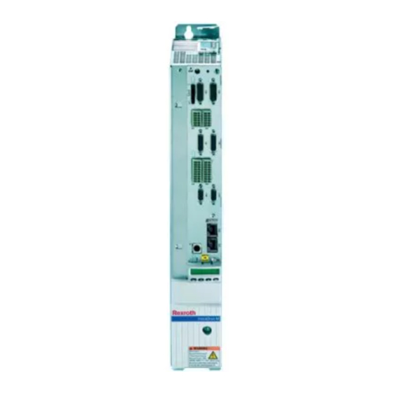
- Page 1 DATASHEET BOSCH REXROTH HNF01.1A-F240-R0026-A-480-NNNN OTHER SYMBOLS: RGB ELEKTRONIKA AGACIAK CIACIEK SPÓŁKA JAWNA Jana Dlugosza 2-6 Street 51-162 Wrocław www.rgbelektronika.pl Poland biuro@rgbelektronika.pl +48 71 325 15 05 www.rgbautomatyka.pl www.rgbautomatyka.pl www.rgbelektronika.pl...
- Page 2 YOUR PARTNER IN MAINTENANCE Repair this product with RGB ELEKTRONIKA ORDER A DIAGNOSIS LINEAR ENCODERS SYSTEMS INDUSTRIAL COMPUTERS ENCODERS CONTROLS SERVO AMPLIFIERS MOTORS MACHINES OUR SERVICES POWER SUPPLIERS OPERATOR SERVO PANELS DRIVERS At our premises in Wrocław, we have a fully equipped servicing facility. Here we perform all the repair works and test each later sold unit.
- Page 3 Industrial Electric Drives Linear Motion and Service Mobile Hydraulics and Controls Assembly Technologies Pneumatics Automation Hydraulics Rexroth IndraDrive M R911295014 Drive Controllers Edition 04 Power Sections Project Planning Manual...
- Page 4 About this Documentation Rexroth IndraDrive M IndraDrive M Title Drive Controllers Power Sections Project Planning Manual Type of Documentation DOK-INDRV*-HMS+HMD****-PR04-EN-P Document Typecode Document number 120-2400-B302-04/EN Internal File Reference Record of Revisions Description Release Notes Date DOK-INDRV*-HMS+HMD****-PR01-EN-P 11.2003 first edition DOK-INDRV*-HMS+HMD****-PR02-EN-P 04.2004...
-
Page 5: Table Of Contents
Rexroth IndraDrive M Contents Contents Introduction Documentation..........................1-1 Purpose of Documentation ...................... 1-1 Documentations - Overview ....................1-2 Basic Structure of a Drive Controller .................... 1-3 General Informations on Installing Drive Controllers ..............1-4 Important Directions for Use Appropriate Use..........................2-1 Introduction .......................... - Page 6 Contents Rexroth IndraDrive M Dimensional Drawing for HMD01.1N-W0012................5-1 Dimensional Drawing for HMD01.1N-W0020................5-2 Dimensional Drawing for HMD01.1N-W0036................5-3 Dimensional Drawing for HMS01.1N-W0020 and HMS01.1N-W0036 ........5-4 Dimensional Drawing for HMS01.1N-W0054 ................5-5 Dimensional Drawing for HMS01.1N-W0070 ................5-6 Dimensional Drawing for HMS01.1N-W0150 ................5-7 Dimensional Drawing for HMS01.1N-W0210 ................
- Page 7 Rexroth IndraDrive M Contents Helpdesk ............................9-1 Service-Hotline ..........................9-1 Internet............................9-1 Vor der Kontaktaufnahme... - Before contacting us..............9-1 Kundenbetreuungsstellen - Sales & Service Facilities ..............9-2 10 Index 10-1 DOK-INDRV*-HMS+HMD****-PR04-EN-P...
- Page 8 Contents Rexroth IndraDrive M DOK-INDRV*-HMS+HMD****-PR04-EN-P...
-
Page 9: Introduction
"Rexroth IndraDrive Drive System" (DOK-INDRV*- SYSTEM*****-PRxx-EN-P; part no. R911309636) into account. For complete project planning of a Rexroth IndraDrive drive system you need, in any case, the Project Planning Manual "Rexroth IndraDrive Drive System" (DOK-INDRV*-SYSTEM*****-PRxx-EN-P; part no. R911309636). This Project Planning Manual, among other things, contains: •... -
Page 10: Documentations - Overview
Introduction Rexroth IndraDrive M Documentations - Overview Title Type of Documentation Document Typecode Rexroth IndraDrive Project Planning Manual DOK-INDRV*-SYSTEM*****-PRxx-EN-P Drive System Rexroth IndraDrive Project Planning Manual DOK-INDRV*-CSH********-PRxx-EN-P Drive Controllers Control Sections Rexroth IndraDrive M Project Planning Manual DOK-INDRV*-HMS+HMD****-PRxx-EN-P Drive Controllers... -
Page 11: Basic Structure Of A Drive Controller
Rexroth IndraDrive M Introduction Basic Structure of a Drive Controller lt_rtf2.fh7 Power section Control section Fig. 1-2: Basic structure of a drive controller The drive controller consists of two essential parts: • Power section • Control section Power Section The following are connected to the power section: •... -
Page 12: General Informations On Installing Drive Controllers
This protects the electronic components (permitted in accordance with EN 60204-1). During their routine check test, Rexroth drive components are tested for high voltage and insulation in accordance with EN 50178. -
Page 13: Important Directions For Use
The user alone carries all responsibility of the risks. Before using Rexroth products, make sure that all the pre-requisites for an appropriate use of the products are satisfied: • Personnel that in any way, shape or form uses our products must first read and understand the relevant safety instructions and be familiar with appropriate use. -
Page 14: Areas Of Use And Application
Important Directions for Use Rexroth IndraDrive M Areas of Use and Application Drive controllers made by Bosch Rexroth are designed to control electrical motors and monitor their operation. Control and monitoring of the motors may require additional sensors and actors. -
Page 15: Safety Instructions For Electric Drives And Controls
Follow these safety instructions at all times. • Bosch Rexroth AG is not liable for damages resulting from failure to observe the warnings provided in this documentation. • Read the operating, maintenance and safety instructions in your language before starting up the machine. - Page 16 Safety Instructions for Electric Drives and Controls Rexroth IndraDrive M • The devices have been designed for installation in industrial machinery. • The ambient conditions given in the product documentation must be observed. • Only use safety-relevant applications that are clearly and explicitly approved in the Project Planning Manual.
-
Page 17: Explanation Of Warning Symbols And Degrees Of Hazard Seriousness
Rexroth IndraDrive M Safety Instructions for Electric Drives and Controls Explanation of Warning Symbols and Degrees of Hazard Seriousness The safety instructions describe the following degrees of hazard seriousness. The degree of hazard seriousness informs about the consequences resulting from non-compliance with the safety instructions:... -
Page 18: Hazards By Improper Use
Safety Instructions for Electric Drives and Controls Rexroth IndraDrive M Hazards by Improper Use High electric voltage and high working current! Risk of death or severe bodily injury by electric shock! DANGER Dangerous movements! Danger to life, severe bodily harm or material damage by... -
Page 19: Instructions With Regard To Specific Dangers
Rexroth IndraDrive M Safety Instructions for Electric Drives and Controls Instructions with Regard to Specific Dangers Protection Against Contact with Electrical Parts Note: This section only concerns devices and drive components with voltages of more than 50 Volt. Contact with parts conducting voltages above 50 Volts can cause personal danger and electric shock. -
Page 20: Protection Against Electric Shock By Protective Low Voltage (Pelv)
Protection Against Electric Shock by Protective Low Voltage (PELV) All connections and terminals with voltages between 5 and 50 Volt at Rexroth products are protective extra-low voltage systems which are provided with touch guard according to the product standards. High electric voltage by incorrect connection! Risk of death or bodily injury by electric shock! ⇒... -
Page 21: Protection Against Dangerous Movements
Rexroth IndraDrive M Safety Instructions for Electric Drives and Controls Protection Against Dangerous Movements Dangerous movements can be caused by faulty control of connected motors. Some common examples are: • improper or wrong wiring of cable connections • incorrect operation of the equipment components •... - Page 22 Safety Instructions for Electric Drives and Controls Rexroth IndraDrive M Dangerous movements! Danger to life, risk of injury, severe bodily harm or material damage! ⇒ For the above reasons, ensure personal safety by means of qualified and tested higher-level monitoring DANGER devices or measures integrated in the installation.
-
Page 23: Protection Against Magnetic And Electromagnetic Fields During Operation And Mounting
Rexroth IndraDrive M Safety Instructions for Electric Drives and Controls ⇒ Disconnect electrical power to the equipment using a master switch and secure the switch against reconnection for: maintenance and repair work cleaning of equipment - long periods of discontinued equipment use Prevent the operation of high-frequency, remote ⇒... -
Page 24: Protection Against Contact With Hot Parts
3-10 Safety Instructions for Electric Drives and Controls Rexroth IndraDrive M Protection Against Contact with Hot Parts Hot surfaces at motor housings, on drive controllers or chokes! Danger of injury! Danger of burns! ⇒ Do not touch surfaces of device housings and... -
Page 25: Protection During Handling And Mounting
3-11 Rexroth IndraDrive M Safety Instructions for Electric Drives and Controls Protection During Handling and Mounting In unfavorable conditions, handling and assembling certain parts and components in an improper way can cause injuries. Risk of injury by improper handling! Bodily injury by bruising, shearing, cutting, hitting! ⇒... -
Page 26: Protection Against Pressurized Systems
3-12 Safety Instructions for Electric Drives and Controls Rexroth IndraDrive M Protection Against Pressurized Systems According to the information given in the Project Planning Manuals, motors cooled with liquid and compressed air, as well as drive controllers, can be partially supplied with externally fed, pressurized media, such as compressed air, hydraulics oil, cooling liquids, and cooling lubricating agents. -
Page 27: Identifying And Checking The Delivered Components
Rexroth IndraDrive M Identifying and Checking the Delivered Components Identifying and Checking the Delivered Components Device Types Type Code Note: The following illustrates the basic structure of the type codes. Your sales representative will help with the current status of available versions. - Page 28 Identifying and Checking the Delivered Components Rexroth IndraDrive M Double-Axis Drive Controllers Abbrev. Column 1 2 3 4 6 7 8 9 1 2 3 4 6 7 8 9 1 2 3 4 6 7 8 9 1 2 3 4 6 7 8 9 H M D 0 1 .
-
Page 29: Type Plates On The Drive Controller
Rexroth IndraDrive M Identifying and Checking the Delivered Components Type Plates on the Drive Controller lt_rt_typenschilderf2.fh7 Power section type plate Control section type plate Fig. 4-3: Type plate arrangement DOK-INDRV*-HMS+HMD****-PR04-EN-P... -
Page 30: Scope Of Delivery
Identifying and Checking the Delivered Components Rexroth IndraDrive M Scope of Delivery Overview As standard Optional Power section Control section Touch guard Shielding plate for motor cable DC bus rails Control voltage rails MultiMediaCard (MMC) Grounding bracket Fig. 4-4: Scope of delivery... -
Page 31: Mechanical Data
Mechanical Data Dimensions Dimensional Drawing for HMD01.1N-W0012 minimum mounting clearance (plus space for motor cable) Note: Rexroth IndraDrive supply units require a greater minimum mounting clearance! view from the rear! dimension for accessories HAS02.1 (motor cable routing with 45°) dimension for accessories HAS02.1 (motor cable routing horizontal) Fig. -
Page 32: Dimensional Drawing For Hmd01.1N-W0020
Mechanical Data Rexroth IndraDrive M Dimensional Drawing for HMD01.1N-W0020 minimum mounting clearance (plus space for motor cable) Note: Rexroth IndraDrive supply units require a greater minimum mounting clearance! view from the rear! dimension for accessories HAS02.1 (motor cable routing with 45°) dimension for accessories HAS02.1 (motor cable routing horizontal) -
Page 33: Dimensional Drawing For Hmd01.1N-W0036
Rexroth IndraDrive M Mechanical Data Dimensional Drawing for HMD01.1N-W0036 minimum mounting clearance (plus space for motor cable) Note: Rexroth IndraDrive supply units require a greater minimum mounting clearance! view from the rear! dimension for accessories HAS02.1 (motor cable routing with 45°) dimension for accessories HAS02.1 (motor cable routing horizontal) -
Page 34: Dimensional Drawing For Hms01.1N-W0020 And Hms01.1N-W0036
Rexroth IndraDrive M Dimensional Drawing for HMS01.1N-W0020 and HMS01.1N-W0036 minimum mounting clearance (plus space for motor cable) Note: Rexroth IndraDrive supply units require a greater minimum mounting clearance! view from the rear! dimension for accessories HAS02.1 (motor cable routing with 45°) dimension for accessories HAS02.1 (motor cable routing horizontal) -
Page 35: Dimensional Drawing For Hms01.1N-W0054
Rexroth IndraDrive M Mechanical Data Dimensional Drawing for HMS01.1N-W0054 minimum mounting clearance (plus space for motor cable) Note: Rexroth IndraDrive supply units require a greater minimum mounting clearance! view from the rear! dimension for accessories HAS02.1 (motor cable routing with 45°) dimension for accessories HAS02.1 (motor cable routing horizontal) -
Page 36: Dimensional Drawing For Hms01.1N-W0070
Mechanical Data Rexroth IndraDrive M Dimensional Drawing for HMS01.1N-W0070 minimum mounting clearance (plus space for motor cable) Note: Rexroth IndraDrive supply units require a greater minimum mounting clearance! view from the rear! dimension for accessories HAS02.1 (motor cable routing with 45°) dimension for accessories HAS02.1 (motor cable routing horizontal) -
Page 37: Dimensional Drawing For Hms01.1N-W0150
Rexroth IndraDrive M Mechanical Data Dimensional Drawing for HMS01.1N-W0150 minimum mounting clearance (plus space for motor cable) Note: Rexroth IndraDrive supply units require a greater minimum mounting clearance! view from the rear! dimension for accessories HAS02.1 (motor cable routing horizontal) dimension for accessories HAS02.1 (motor cable routing with 45°) -
Page 38: Dimensional Drawing For Hms01.1N-W0210
Mechanical Data Rexroth IndraDrive M Dimensional Drawing for HMS01.1N-W0210 minimum mounting clearance (plus space for motor cable) Note: Rexroth IndraDrive supply units require a greater minimum mounting clearance! view from the rear! dimension for accessories HAS02.1 (motor cable routing horizontal) dimension for accessories HAS02.1 (motor cable routing with 45°) -
Page 39: Weight
Rexroth IndraDrive M Mechanical Data Weight Drive controller Weight [kg] HMD01.1N-W0012 5.52 HMD01.1N-W0020 5.66 HMD01.1N-W0036 7.52 HMS01.1N-W0020 5.27 HMS01.1N-W0036 5.27 HMS01.1N-W0054 6.68 HMS01.1N-W0070 7.94 HMS01.1N-W0150 12.74 HMS01.1N-W0210 18.44 Fig. 5-9: Weight of drive controllers (without control section and accessories) Note: Weight of control section: 0.4 kg. - Page 40 5-10 Mechanical Data Rexroth IndraDrive M Notes DOK-INDRV*-HMS+HMD****-PR04-EN-P...
-
Page 41: Electrical Data
Rexroth IndraDrive M Electrical Data Electrical Data Note: The adjustable pulse frequency (4, 8, 12 resp. 16 kHz) depends on the firmware and the control section. The capacity of the drive controllers is described below with examples of load profiles. The examples distinguish applications for servo operation (400 ms) and main spindle operation (2 s resp. -
Page 42: Power Section Hmd01.1N (W0012, W0020, W0036)
Especially when using standard motors, make sure that they can withstand the voltage load. Observe section "Using Third-Party Motors in Drive System Rexroth IndraDrive" of the Project Planning Manual "Rexroth IndraDrive Drive System". Note: Depending on the electric rotational frequency, the output current is reduced for thermal protection of the power section. -
Page 43: Power Dissipation
Rexroth IndraDrive M Electrical Data Power Dissipation The level of power dissipation occurring in power sections can be ascertained from the following. In the diagrams basic and current-related power dissipation are summarized. HMD01.1N-W0012 Verlustleistung HMD01.1N-W0012 4 kHz 8 kHz P 4kHz i out_4kHz... - Page 44 Electrical Data Rexroth IndraDrive M HMD01.1N-W0020 Verlustleistung HMD01.1N-W0020 4 kHz 8 kHz P 4kHz i out_4kHz P 8kHz i out_8kHz i out_4kHz i out_8kHz Power dissipation Current (r.m.s value) Fig. 6-3: Power dissipation HMD01.1N-W0020 DOK-INDRV*-HMS+HMD****-PR04-EN-P...
- Page 45 Rexroth IndraDrive M Electrical Data HMD01.1N-W0036 Verlustleistung HMD01.1N-W0036 4 kHz 8 kHz P 4kHz i out_4kHz P 8kHz i out_8kHz i out_4kHz i out_8kHz Power dissipation Current (r.m.s value) Fig. 6-4: Power dissipation HMD01.1N-W0036 DOK-INDRV*-HMS+HMD****-PR04-EN-P...
-
Page 46: Examples Of Allowed Load Profiles
Electrical Data Rexroth IndraDrive M Examples of Allowed Load Profiles Designation Symbol Unit HMD01.1N- HMD01.1N- HMD01.1N- W0012* W0020 W0036 Characteristic curve output current; operation at overload out_peak Peak load allowance: Iout_peak out_base Iout_base Maximum output 12,0 20,0 36,0 out_peak_1 (4 kHz) -
Page 47: Power Section Hms01.1N (W0020, W0036, W0054, W0070)
Especially when using standard motors, make sure that they can withstand the voltage load. Observe section "Using Third-Party Motors in Drive System Rexroth IndraDrive" of the Project Planning Manual "Rexroth IndraDrive Drive System". DOK-INDRV*-HMS+HMD****-PR04-EN-P... -
Page 48: Power Dissipation
Electrical Data Rexroth IndraDrive M Note: Depending on the electric rotational frequency, the output current is reduced for thermal protection of the power section. The output current is reduced when the value of the electric rotational frequency falls below 3 Hz. - Page 49 Rexroth IndraDrive M Electrical Data HMS01.1N-W0036 Verlustleistung HMS01.1N-W0036 10 kHz 16 kHz 12 kHz 8 kHz 4 kHz P 4kHz i out_4kHz P 8kHz i out_8kHz P 10kHz i out_10kHz P 12kHz i out_12kHz P 16kHz i out_16kHz i out_4kHz i out_8kHz...
- Page 50 6-10 Electrical Data Rexroth IndraDrive M HMS01.1N-W0054 Verlustleistung HMS01.1N-W0054 4 kHz 10 kHz 12 kHz 8 kHz 16 kHz P 4kHz i out_4kHz P 8kHz i out_8kHz P 10kHz i out_10kHz P 12kHz i out_12kHz P 16kHz i out_16kHz 12.5 17.5 20...
- Page 51 6-11 Rexroth IndraDrive M Electrical Data HMS01.1N-W0070 Verlustleistung HMS01.1N-W0070 16 kHz 4 kHz 12 kHz 10 kHz 8 kHz P 4kHz i out_4kHz P 8kHz i out_8kHz P 10kHz i out_10kHz P 12kHz i out_12kHz P 16kHz i out_16kHz i out_4kHz i out_8kHz...
- Page 52 6-12 Electrical Data Rexroth IndraDrive M Power Section - Examples of Allowed Load Profiles The capacity of the drive controllers is described below with examples of load profiles. Designation Symbol Unit HMS01.1N- HMS01.1N- HMS01.1N- HMS01.1N- W0020 W0036 W0054 W0070 Characteristic curve output current;...
- Page 53 6-13 Rexroth IndraDrive M Electrical Data Designation Symbol Unit HMS01.1N- HMS01.1N- HMS01.1N- HMS01.1N- W0020 W0036 W0054 W0070 12,4 21,9 37,7 44,1 Maximum output out_peak_5 (4 kHz) current 15,5 21,6 25,1 out_peak_5 (8 kHz) t=60s; T=10min; K=1,2 13,2 15,0 out_peak_5 (12 kHz)
-
Page 54: Power Section Hms01.1N- (W0150, W0210)
Especially when using standard motors, make sure that they can withstand the voltage load. Observe section "Using Third-Party Motors in Drive System Rexroth IndraDrive" of the Project Planning Manual "Rexroth IndraDrive Drive System". DOK-INDRV*-HMS+HMD****-PR04-EN-P... -
Page 55: Power Dissipation
6-15 Rexroth IndraDrive M Electrical Data Note: Depending on the electric rotational frequency, the output current is reduced for thermal protection of the power section. The output current is reduced when the value of the electric rotational frequency falls below 3 Hz. - Page 56 6-16 Electrical Data Rexroth IndraDrive M HMS01.1N-W0210 Verlustleistung HMS01.1N-W0210 1800 10 kHz 16 kHz 12 kHz 8 kHz 4 kHz 1600 1400 P 4kHz i out_4kHz 1200 P 8kHz i out_8kHz 1000 P 10kHz i out_10kHz P 12kHz i out_12kHz...
- Page 57 6-17 Rexroth IndraDrive M Electrical Data Examples of Allowed Load Profiles Designation Symbol Unit HMS01.1N-W0150 HMS01.1N-W0210 Characteristic curve out_peak output current; operation at overload Peak load allowance: out_base Iout_peak Iout_base 150,0 210,0 out_peak_1 (4 kHz) Maximum output 130,3 183,9 Iout_peak_1 (8 kHz)
- Page 58 6-18 Electrical Data Rexroth IndraDrive M Note: The load profiles are available if particularly the maximum current at switching frequencies of 8, 12 and 16 Hz is externally (e.g. by an NC) limited to the indicated values. DOK-INDRV*-HMS+HMD****-PR04-EN-P...
-
Page 59: Control Voltage
6-19 Rexroth IndraDrive M Electrical Data Control Voltage Note: The data below apply to the power sections. The data refer to an ambient temperature of 25 °C. Designation Symbol Unit Value • 24 ±20% Control voltage (when no motor holding brake is used) •... - Page 60 6-20 Electrical Data Rexroth IndraDrive M Designation Symbol Unit Value Max. charging current EIN3 Max. pulse duration of I EIN3 EIN3Lade Max. input capacity 0.47 Power consumption*: HMD01.1-1N-W0012 16.6 16.6 HMD01.1-1N-W0020 HMD01.1-1N-W0036 10.8 10.1 HMS01.1-1N-W0020 15.1 HMS01.1-1N-W0036 HMS01.1-1N-W0054 16.1 HMS01.1-1N-W0070 HMS01.1-1N-W0150...
-
Page 61: Connections
6-21 Rexroth IndraDrive M Electrical Data Connections Complete Connection Diagram HMS01.1-Wxxxx MotTemp- MotTemp+ 0VBr +24VBr Ap5420f3.FH7 Fig. 6-18: Complete connection diagram DOK-INDRV*-HMS+HMD****-PR04-EN-P... -
Page 62: Overview
6-22 Electrical Data Rexroth IndraDrive M Overview HMS01.1N-W0020 and HMS01.1N-W0036, HMD01.1N-W0020 and HMD01.1N-W0036 X1 out X1 in +24 V control voltage DC bus equipment grounding conductor hms0020_frontf2.fh7 Fig. 6-19: HMS01.1N-W0020 and HMS01.1N-W0036, HMD01.1N-W0020 and HMD01.1N-W0036 power section connections (front) Description of connections:... - Page 63 6-23 Rexroth IndraDrive M Electrical Data X5.1 X5.2 X6.2 X6.1 hms0020_x5_x6.fh7 hmd0036_x5_x6.fh7 Fig. 6-20: HMS01.1N-W0020, -W0036, HMD01.1N-W0020, -W0036 power section connections (bottom) Description of connections: Connection See page X5: motor connection (HMS) 6-29 X5.1, X5.2: motor connections (HMD) X6: motor temperature, motor holding brake (HMS) 6-31 X6.1, X6.2: motor temperature, motor holding brake (HMD)
- Page 64 6-24 Electrical Data Rexroth IndraDrive M HMS01.1N-W0054 and HMS01.1N-W0070 X1 out X1 in +24 V control voltage DC bus equipment grounding conductor hms0070_frontf2 Fig. 6-21: HMS01.1N-W0054 and -W0070 power section connections (front) Description of connections: Connection See page control voltage...
- Page 65 6-25 Rexroth IndraDrive M Electrical Data hms0070_x5_x6.fh7 Fig. 6-22: HMS01.1N-W0054 and -W0070 power section connections (bottom) Description of connections: Connection See page X5: motor connection 6-29 X6: motor temperature, motor holding brake 6-31 XS2: shield connection motor cable 6-36 DOK-INDRV*-HMS+HMD****-PR04-EN-P...
- Page 66 6-26 Electrical Data Rexroth IndraDrive M HMS01.1N-W0150 and HMS01.1N-W0210 X1 in X1 out +24 V control voltage DC bus equipment grounding equipment conductor grounding conductor motor connection plate for shield connection motor cable (optional) hms0140_front.fh7 Fig. 6-23: HMS01.1N-W0150 HMS01.1N-W0210 power...
- Page 67 6-27 Rexroth IndraDrive M Electrical Data hms0140_x5_x6.fh7 Fig. 6-24: HMS01.1N-W0150 and HMS01.1N-W0210 power section connections (bottom) Description of connections: Connection See page X6: motor temperature, motor holding brake 6-31 XS2: shield connection motor cable 6-36 DOK-INDRV*-HMS+HMD****-PR04-EN-P...
-
Page 68: Control Voltage (+24 V, 0 V)
6-28 Electrical Data Rexroth IndraDrive M Control Voltage (+24 V, 0 V) The control voltage supply is connected by contact rails and screws (M6) Design to the front of the drive controller (cross section of a contact rail: 6 x 12 mm). There are various lengths of contact rail depending on the width of the drive controllers. -
Page 69: X5 Resp. X5.1/X5.2, Motor Connection
Fig. 6-28: Coding pins at X5.1 and X5.2 If you use prefabricated Rexroth motor cables you must code the motor cable connector for X5.2 first. This means that you have to set the coding pin of the connector (not the coding pin of the bushing of the drive controller!) from pin 1 to pin 2. - Page 70 Connecting the Motor Power Note: If you use third-party motor power cables not corresponding to Cable the requirements, Rexroth's guarantee for the drive system will expire (see Project Planning Manual "Rexroth IndraDrive Drive System" (DOK-INDRV*-SYSTEM*****-PRxx-EN-P; part no. R911309636)). Use ready-made Rexroth cables (see documentation "Rexroth Connection Cables"...
-
Page 71: X6 Resp. X6.1/X6.2, Motor Temperature Monitoring And Motor Holding Brake
• X6.2: coding pin 1 Fig. 6-33: Coding pins at X6.1 and X6.2 If you use prefabricated Rexroth motor cables you must code the motor cable connectors for X6.1 and X6.2 first (Do not change the codings at the bushings of the drive controller!): •... - Page 72 6-32 Electrical Data Rexroth IndraDrive M Connection Cross Section HMS01.1N-W0020 to -W0070 and HMD01.1N-W0012 to -W0036: Cross section Cross section Cross section single-wire multiwire in AWG [mm²] [mm²] 0.14-1.5 0.14-1.5 28-16 Fig. 6-34: Connection cross section HMS01.1N-W0150 to -W0210: Cross section...
- Page 73 6-33 Rexroth IndraDrive M Electrical Data Maximum permitted braking current: • HMS01.1N-W0020: 1.6 A • HMS01.1N-W0036: 1.6 A • HMS01.1N-W0054: 2.0 A ATTENTION • HMS01.1N-W0070: 2.0 A • HMS01.1N-W0150: 2.5 A • HMS01.1N-W0210: 2.5 A • HMD01.1N-W0012: 1,5 A each axis •...
-
Page 74: Ground Connection Of Housing
6-34 Electrical Data Rexroth IndraDrive M Ground Connection of Housing The ground connection of the housing is used to provide functional safety of the drive controllers and protection against contact in conjunction with the equipment grounding conductor connection. Ground the housings of the drive controllers: 1. -
Page 75: Equipment Grounding Conductor Connection
6-35 Rexroth IndraDrive M Electrical Data Equipment Grounding Conductor Connection Lethal electric shock caused by live parts with more than 50 V! Via the joint bar on the front connect the drive ⇒ controller to the supply unit. DANGER ⇒... -
Page 76: Xs1, Shield Connection (Control Wires)
6-36 Electrical Data Rexroth IndraDrive M XS1, Shield Connection (Control Wires) XS1f2 Fig. 6-38: XS1 shield connection Connection for shields of lines connected to the control section (only for lines with connectors, which do not have their own shield connection). -
Page 77: Touch Guard
Rexroth IndraDrive M Touch Guard Touch Guard Lethal electric shock caused by live parts with more than 50 V! The appropriate touch guard must be mounted for ⇒ each drive controller following connection work. WARNING ⇒ Never mount a damaged touch guard. -
Page 78: Mounting
Touch Guard Rexroth IndraDrive M Mounting hms_beruehrschutz.fh7 Fig. 7-2: Touch guard The touch guard must always be mounted following connection work. Note: Risk of damage to the touch guard! Regard the maximum tightening torque for the fixing screw for the touch guard. -
Page 79: Disposal And Environmental Protection
Rexroth IndraDrive M Disposal and Environmental Protection Disposal and Environmental Protection Disposal Products Our products can be returned to us free of charge for disposal. It is a precondition, however, that the products are free of oil, grease or other dirt. -
Page 80: Recycling
Disposal and Environmental Protection Rexroth IndraDrive M Recycling Due to their high content of metal most of the product components can be recycled. In order to recycle the metal in the best possible way it is necessary to disassemble the products into individual modules. -
Page 81: Helpdesk
Rexroth IndraDrive M Service & Support Service & Support Helpdesk Unser Kundendienst-Helpdesk im Hauptwerk Lohr Our service helpdesk at our headquarters in Lohr am am Main steht Ihnen mit Rat und Tat zur Seite. Main, Germany can assist you in all kinds of inquiries. -
Page 82: Kundenbetreuungsstellen - Sales & Service Facilities
Service & Support Rexroth IndraDrive M Kundenbetreuungsstellen - Sales & Service Facilities Deutschland – Germany vom Ausland: (0) nach Landeskennziffer weglassen! from abroad: don’t dial (0) after country code! Vertriebsgebiet Mitte S E R V I C E A U T O M A T I O N... - Page 83 Rexroth IndraDrive M Service & Support Europa (West) - Europe (West) vom Ausland: (0) nach Landeskennziffer weglassen, Italien: 0 nach Landeskennziffer mitwählen from abroad: don’t dial (0) after country code, Italy: dial 0 after country code Austria - Österreich Austria –...
- Page 84 Service & Support Rexroth IndraDrive M Europa (Ost) - Europe (East) vom Ausland: (0) nach Landeskennziffer weglassen from abroad: don’t dial (0) after country code Czech Republic - Tschechien Czech Republic - Tschechien Hungary - Ungarn Poland – Polen DEL a.s.
- Page 85 Rexroth IndraDrive M Service & Support Africa, Asia, Australia – incl. Pacific Rim Australia - Australien Australia - Australien China China AIMS - Australian Industrial Bosch Rexroth Pty. Ltd. Shanghai Bosch Rexroth Shanghai Bosch Rexroth Machinery Services Pty. Ltd. No. 7, Endeavour Way Hydraulics &...
- Page 86 Canada West - Kanada West Mexico Mexico Bosch Rexroth Canada Corporation Bosch Rexroth Canada Corporation Bosch Rexroth Mexico S.A. de C.V. Bosch Rexroth S.A. de C.V. Burlington Division 5345 Goring St. Calle Neptuno 72 Calle Argentina No 3913 3426 Mainway Drive Burnaby, British Columbia Unidad Ind.
-
Page 87: Index
10-1 Rexroth IndraDrive M Index Index appropriate use 2-1 Brake motor holding brake 6-31 Braking current 6-33 Bus module 6-28 Coding pins X5.1, X5.2 6-29 X6.1, X6.2 6-31 Connection bus module 6-28 diagram 6-21 motor 6-29 motor holding brake 6-31... - Page 88 10-2 Index Rexroth IndraDrive M HMD 4-2 HMS 4-1 Holding brake 6-31 inappropriate use 2-2 IndraDrive documentation 1-2 Installation connection diagram 6-21 electrical 1-4 joint bar 6-35 Materials of products 8-1 Mechanical data 5-1 Motor connection 6-29 holding brake 6-31...
- Page 89 10-3 Rexroth IndraDrive M Index X1 6-28 X5 6-29 X5.1 6-29 X5.2 6-29 X6 6-31 X6.1 6-31 X6.2 6-31 XS1 6-36 XS2 6-36 DOK-INDRV*-HMS+HMD****-PR04-EN-P...
- Page 90 10-4 Index Rexroth IndraDrive M DOK-INDRV*-HMS+HMD****-PR04-EN-P...
- Page 92 Bosch Rexroth AG Electric Drives and Controls P.O. Box 13 57 97803 Lohr, Germany Bgm.-Dr.-Nebel-Str. 2 97816 Lohr, Germany Phone +49 93 52-40-50 60 +49 93 52-40-49 4 1 service.svc@boschrexroth.de www.boschrexroth.com Printed in Germany R911295014 DOK-INDRV*-HMS+HMD****-PR04-EN-P...
Need help?
Do you have a question about the IndraDrive M and is the answer not in the manual?
Questions and answers