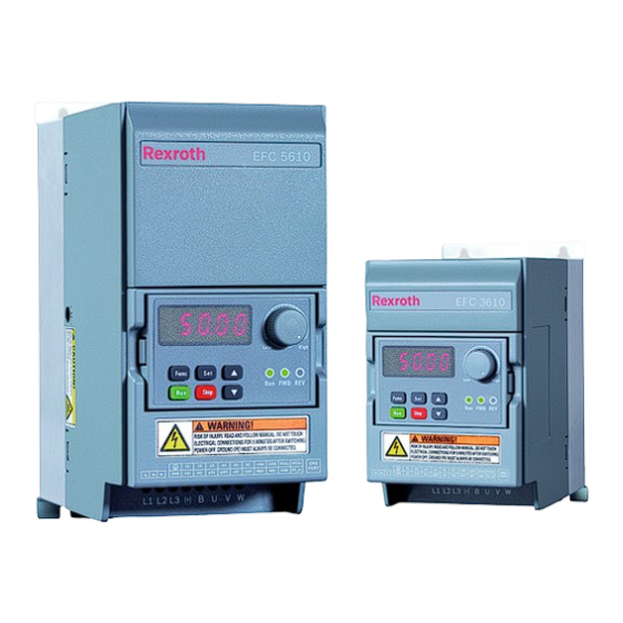
REXROTH EFC 3610 Series Operating Instructions Manual
Frequency converter
efc x610 series
Hide thumbs
Also See for EFC 3610 Series:
- Operating instructions manual (422 pages) ,
- Quick start manual (94 pages)

Subscribe to Our Youtube Channel
Related Manuals for REXROTH EFC 3610 Series


Summary of Contents for REXROTH EFC 3610 Series
- Page 1 The Drive & Control Company Rexroth Frequency Converter EFC 3610 / EFC 5610 Series Operating Instructions Edition 03 R912005854...
- Page 2 This document, as well as the data, specifications and other information set forth in it, are the exclusive property of Bosch Rexroth (Xi'an) Electric Drives and Controls Co., Ltd. It may not be reproduced or given to third parties without its consent.
- Page 3 EFC x610 Series Bosch Rexroth AG Deutsch English Français Lebensgefahr bei Danger to life in Danger de Nichtbeachtung der nachstehenden case of non‑compliance with the mort en cas de non‑respect des Sicherheitshinweise! below-mentioned safety consignes de sécurité figurant ci- instructions! après !
- Page 4 Bosch Rexroth AG EFC x610 Series Deutsch English Français Electromagnetic / Champs Elektromagnetische / magnetische magnetic fields! Health hazard for électromagnétiques / magnétiques ! Felder! Gesundheitsgefahr für persons with heart pacemakers, Risque pour la santé des porteurs de Personen mit Herzschrittmachern, metal implants or hearing aids! stimulateurs cardiaques, d’implants...
- Page 5 Rexroth competente. en el idioma de su país, diríjase a su responsável da Rexroth. distribuidor competente de Rexroth. Solo personale qualificato può Apenas pessoal qualificado pode eseguire lavori sui componenti di Solo el personal debidamente trabalhar nos componentes de comando.
- Page 6 Bosch Rexroth AG EFC x610 Series Español Português Italiano Campi ¡Campos Campos elettromagnetici / magnetici! Pericolo electromagnéticos/magnéticos! eletromagnéticos / magnéticos! per la salute delle persone portatrici ¡Peligro para la salud de las personas Perigo de saúde para pessoas com di pacemaker, protesi metalliche o con marcapasos, implantes marcapassos, implantes metálicos...
- Page 7 Kontakta din Rexroth-återförsäljare givne anvisninger. om dokumentationen inte medföljer Mocht u niet beschikken over på ditt språk. Kontakt din Rexroth-forhandler, hvis documenten in uw landstaal, kunt u dokumentationen ikke medfølger på contact opnemen met uw plaatselijke Endast kvalificerad personal får dit sprog.
- Page 8 Bosch Rexroth AG EFC x610 Series Svenska Dansk Nederlands Elektromagnetiska/ magnetiska fält! Hälsofara för Elektromagnetiske/magnetiske Elektromagnetische / magnetische personer med pacemaker, implantat felter! Sundhedsfare for personer velden! Gevaar voor de gezondheid av metall eller hörapparat! med pacemakere, metalliske van personen met pacemakers, implantater eller høreapparater!
- Page 9 EFC x610 Series Bosch Rexroth AG Suomi Polski Český Näiden Zagrożenie Nebezpečí života v turvaohjeiden noudattamatta życia w razie nieprzestrzegania případě nedodržení níže uvedených jättämisestä on seurauksena poniższych wskazówek bezpečnostních pokynů! hengenvaara! bezpieczeństwa! Před uvedením výrobků do provozu si Ota tuote käyttöön vasta sen jälkeen, Nie uruchamiać...
- Page 10 Bosch Rexroth AG EFC x610 Series Suomi Polski Český Pola Elektromagnetická/ Sähkömagneettisia/magneettisia elektromagnetyczne / magnetyczne! magnetická pole! Nebezpečí pro kenttiä! Terveydellisten haittojen Zagrożenie zdrowia dla osób z zdraví osob s kardiostimulátory, vaara henkilöille, joilla on rozrusznikiem serca, metalowymi kovovými implantáty nebo sydämentahdistin, metallinen...
- Page 11 EFC x610 Series Bosch Rexroth AG Slovensko Slovenčina Română Življenjska Nebezpečenstvo Pericol de nevarnost pri neupoštevanju ohrozenia života pri nedodržiavaní moarte în cazul nerespectării naslednjih napotkov za varnost! nasledujúcich bezpečnostných următoarelor instrucţiuni de pokynov! siguranţă! Izdelke začnite uporabljati šele, ko v celoti preberete, razumete in Výrobky uvádzajte do prevádzky až...
- Page 12 Bosch Rexroth AG EFC x610 Series Slovensko Slovenčina Română Câmpuri Elektromagnetna / magnetna polja! Elektromagnetické/magnetické polia! electromagnetice / magnetice! Pericol Nevarnost za zdravje za osebe s Nebezpečenstvo pre zdravie osôb s pentru sănătatea persoanelor cu spodbujevalniki srca, kovinskimi kardiostimulátormi, kovovými stimulatoare cardiace, implanturi vsadki ali slušnimi aparati!
- Page 13 EFC x610 Series Bosch Rexroth AG Magyar Български Latviski Turpinājumā Опасност за живота при alábbi biztonsági útmutatások doto drošības norādījumu неспазване на посочените по-долу figyelmen kívül hagyása neievērošana var apdraudēt dzīvību! инструкции за безопасност! életveszélyes helyzethez vezethet! Sāciet lietot izstrādājumu tikai pēc Използвайте...
- Page 14 Bosch Rexroth AG EFC x610 Series Magyar Български Latviski Електромагнитни / магнитни Elektromágneses / mágneses mező! Elektromagnētiskais / magnētiskais полета! Опасност за здравето на Káros hatással lehet a szívritmus- lauks! Veselības apdraudējums хора със сърдечни стимулатори, szabályozó készülékkel, personām ar sirds stimulatoriem, метални...
- Page 15 Kui Teil puuduvad emakeelsed materjalid, siis pöörduge Rexrothi Εάν δεν υπάρχει τεκμηρίωση στη Jei Jūs negavote aprašo gimtąja kohaliku müügiesinduse poole. γλώσσα σας, απευθυνθείτε σε kalba, kreipkitės į įgaliotus Rexroth εξουσιοδοτημένο αντιπρόσωπο της atstovus. Ajamikomponentidega tohib töötada Rexroth. üksnes kvalifitseeritud personal.
- Page 16 Bosch Rexroth AG EFC x610 Series Lietuviškai Eesti Ελληνικά Elektromagnetilised / magnetilised väljad! Terviseohtlik Ηλεκτρομαγνητικά/μαγνητικά πεδία! Elektromagnetiniai / magnetiniai südamestimulaatorite, Κίνδυνος για την υγεία ατόμων με laukai! Pavojus asmenų su širdies metallimplantaatide ja καρδιακούς βηματοδότες, μεταλλικά stimuliatoriais, metaliniais implantais kuulmisseadmetega inimestele! εμφυτεύματα...
- Page 17 EFC x610 Series Bosch Rexroth AG 中文 如果不按照下述指定的安全说明使用,将会导致人身伤害! 在没有阅读,理解随本产品附带的文件并熟知正当使用前,不要安装或使用本产品。 如果没有您所在国家官方语言文件说明,请与 Rexroth 销售伙伴联系。 只允许有资格人员对驱动器部件进行操作。 安全说明的详细解释在本文档的第一章。 高电压!电击导致生命危险! 只有在安装了永久良好的设备接地导线后才可以对驱动器的部件进行操作。 在接触驱动器部件前先将驱动器部件断电。 确保电容放电时间。 危险运动!生命危险! 保证设备的运动区域内和移动部件周围无障碍物。 防止人员意外进入设备运动区域内。 在接近或进入危险区域之前,确保传动设备安全停止。 电磁场/磁场!对佩戴心脏起搏器、金属植入物和助听器的人员会造成严重的人身伤害 ! 上述人员禁止进入安装及运行的驱动器区域,或者必须事先咨询医生。 热表面(大于 60 度)!灼伤风险! 不要触摸金属表面(例如散热器)。驱动器部件断电后需要时间进行冷却(至少 15 分钟)。 安装和运输不当导致受伤危险!当心受伤! 使用适当的运输和安装设备。 使用适合的工具及用适当的防护设备。 电池操作不当!受伤风险! 请勿对低电量电池重新激活或重新充电(爆炸和腐蚀的危险)。 请勿拆解或损坏电池。请勿将电池投入明火中。 DOK-RCON03-EFC-X610***-IT03-EN-P...
- Page 18 Bosch Rexroth AG EFC x610 Series DOK-RCON03-EFC-X610***-IT03-EN-P...
-
Page 19: Table Of Contents
EFC x610 Series Bosch Rexroth AG Table of Contents Table of Contents Page Safety Instructions for Electric Drives and Controls......1 Definitions of Terms................1 Explanation of Signal Words and the Safety Alert Symbol....General Information................4 1.3.1 Using the Safety Instructions and Passing Them on to Others....4 1.3.2... - Page 20 Bosch Rexroth AG EFC x610 Series Table of Contents Page 6.1.1 Input....................6.1.2 Output....................6.1.3 V/f Control Performance..............18 6.1.4 SVC Control Performance..............18 6.1.5 Main Functions..................19 6.1.6 Communication..................20 6.1.7 Operating Panel................... 20 6.1.8 Protection.................... 6.1.9 Conditions................... Technical Data..................22 6.2.1...
- Page 21 EFC x610 Series Bosch Rexroth AG Table of Contents Page Control terminals figure............... 48 Control terminals description.............. 49 Digital input NPN / PNP wiring............Digital output DO1a, DO1b load pull-up / pull-down wiring....51 Analog input terminals (AI1, AI2, EAI, +10 V, +5 V, Earth and GND)..
- Page 22 Bosch Rexroth AG EFC x610 Series Table of Contents Page 10.1 LED Panel.................... 10.2 LED Display..................77 10.3 Dust Cover................... 10.4 LED Indicator..................79 10.5 Operating Descriptions................ 80 10.6 Fast Access to Parameters with Button Combinations......10.7 Digit Shifting Function for Modification of Parameter Values....82 Quick Start...................
- Page 23 EFC x610 Series Bosch Rexroth AG Table of Contents Page 12.3 Power Stage Configuration..............110 12.3.1 Set the Control Mode................ 12.3.2 Normal / Heavy Duty Setting.............. 110 12.3.3 Carrier Frequency Setting..............111 12.3.4 Fan Control..................12.3.5 Fan Maintenance Reminder............... 12.4 Basic Frequency Setting Sources............
- Page 24 Bosch Rexroth AG EFC x610 Series Table of Contents Page Start with speed capture..............143 Automatic start / stop according to setting frequency...... 12.5.5 Stop Behavior Setting................ 146 Stop mode setting................DC-braking during deceleration to stop..........147 Overexcitation braking............... 148 12.5.6 Resistor Braking.................
- Page 25 EFC x610 Series Bosch Rexroth AG Table of Contents Page 12.10.1 Converter Protection................. Overload pre-warning................ Stall overvoltage prevention.............. Stall overcurrent prevention.............. Phase loss protection................ Analog Input Broken Wire Detection..........190 12.10.2 Reaction to External Error Signals............. 12.10.3 Motor Protection................192 Motor derating frequency at low speed..........
- Page 26 Bosch Rexroth AG EFC x610 Series Table of Contents Page 13.4.5 Error 5 (OE-2): Overvoltage during Acceleration....... 13.4.6 Error 6 (OE-3): Overvoltage during Deceleration....... 219 13.4.7 Error 7 (OE-4): Overvoltage during Stop........... 13.4.8 Error 8 (UE-1): Undervoltage during Run........... 219 13.4.9 Error 9 (SC): Surge Current or Short Circuit........
- Page 27 EFC x610 Series Bosch Rexroth AG Table of Contents Page 14.2.1 Selection of the Communication Protocol......... 229 14.2.2 Setting the Data Transmission Rate........... 229 14.2.3 Setting the Data Format..............14.2.4 Setting the Local Address..............230 14.2.5 Setting Command Signal Type............230 14.2.6 Communication Disruption and Response........
- Page 28 Bosch Rexroth AG EFC x610 Series Table of Contents Page PKW parameter area................PZD process data area............... 254 14.4.7 Communication parameter configuration.......... Communication related parameter settings........256 Parameter configuration of master............ GSD file....................257 Accessories..................258 15.1 Optional Accessories................. 15.2 Operating Panel.................
- Page 29 EFC x610 Series Bosch Rexroth AG Table of Contents Page Dimensions..................Electric data..................276 15.10 External Brake Resistor..............278 15.10.1 Braking Ratio..................15.10.2 Brake Resistor Type for Braking Ratio of 10 %........15.10.3 Brake Resistor Type for Braking Ratio of 20 %........
- Page 30 Bosch Rexroth AG EFC x610 Series Table of Contents Page b0: Basic system parameters............. 301 19.3.3 Group C: Power Parameters.............. C0: Power control parameters............302 C1: Motor and system parameters............. 304 C2: V/f control parameters..............C3: Vector control parameters............306 19.3.4 Group E: Function Control Parameters..........
-
Page 31: Safety Instructions For Electric Drives And Controls
EFC x610 Series Bosch Rexroth AG Safety Instructions for Electric Drives and Controls 1 Safety Instructions for Electric Drives and Controls 1.1 Definitions of Terms Documentation A documentation comprises the entire documentation used to inform the user of the product about the use and safety-relevant features for configuring, integrat- ing, mounting, installing, commissioning, operating, maintaining, repairing and decommissioning the product. - Page 32 Bosch Rexroth AG EFC x610 Series Safety Instructions for Electric Drives and Controls as well as control and power circuits, which have been assembled for a specific application. A machine is, for example, intended for processing, treatment, movement or packaging of a material. The term "machine" also covers a combi- nation of machines which are arranged and controlled in such a way that they function as a unified whole.
-
Page 33: Explanation Of Signal Words And The Safety Alert Symbol
EFC x610 Series Bosch Rexroth AG Safety Instructions for Electric Drives and Controls 1.2 Explanation of Signal Words and the Safety Alert Symbol The Safety Instructions in the available application documentation contain spe- cific signal words (DANGER, WARNING, CAUTION or NOTICE) and, where re- quired, a safety alert symbol (in accordance with ANSI Z535.6-2011). -
Page 34: General Information
You must follow these safety instructions. Bosch Rexroth is not liable for damages resulting from failure to observe the ● safety instructions. - Page 35 EFC x610 Series Bosch Rexroth AG Safety Instructions for Electric Drives and Controls which measures of risk reduction for personal safety depend on electrical, electronic or programmable control systems. The information given in the application documentation with regard to the use ●...
-
Page 36: Hazards By Improper Use
Bosch Rexroth AG EFC x610 Series Safety Instructions for Electric Drives and Controls 1.3.3 Hazards by Improper Use High electrical voltage and high working current! Danger to life or serious in- ● jury by electric shock! High electrical voltage by incorrect connection! Danger to life or injury by ●... -
Page 37: Instructions With Regard To Specific Dangers
EFC x610 Series Bosch Rexroth AG Safety Instructions for Electric Drives and Controls 1.4 Instructions with Regard to Specific Dangers 1.4.1 Protection Against Contact With Electrical Parts and Housings This section concerns components of the electric drive and control system with voltages higher than 50 volts. -
Page 38: Protective Extra-Low Voltage As Protection Against Electric Shock
On components of an electric drive and control system provided by Bosch Rexroth, all connections and terminals with voltages between 5 and 50 volts are PELV ("Protective Extra-Low Voltage") systems. It is allowed to connect devices equipped with basic insulation (such as programming devices, PCs, notebooks, display units) to these connections. - Page 39 EFC x610 Series Bosch Rexroth AG Safety Instructions for Electric Drives and Controls that faulty drive movements will occur. The extent of faulty drive movements de- pends upon the type of control and the state of operation. Dangerous movements! Danger to life, risk of injury, serious injury or property...
-
Page 40: Protection Against Magnetic And Electromagnetic Fields During Operation And Mounting
Bosch Rexroth AG EFC x610 Series Safety Instructions for Electric Drives and Controls and radio equipment in its possible positions of normal use. It might possibly be necessary to perform a special electromagnetic compatibility (EMC) test. 1.4.4 Protection Against Magnetic and Electromagnetic Fields During... -
Page 41: Protection Against Contact With Hot Parts
EFC x610 Series Bosch Rexroth AG Safety Instructions for Electric Drives and Controls 1.4.5 Protection Against Contact with Hot Parts Hot surfaces of components of the electric drive and control system. Risk of burns! Do not touch hot surfaces of, for example, braking resistors, heat sinks, sup- ●... -
Page 42: Important Directions For Use
The user alone carries all responsibility of the risks. Before using Bosch Rexroth products, make sure that all the pre-requisites for appropriate use of the products are satisfied. Personnel that in any way or form use our products must first read and under- ●... -
Page 43: Documentation Information
Do not attempt to install or put the product into operation until you have com- pletely read and understood the descriptions in this documentation! 3.2 Reference For documentation available in other type or language, please consult your local Bosch Rexroth sales partner or check www.boschrexroth.com/efcx610. Documentation type Short text / Type code Language... -
Page 44: Delivery And Storage
Bosch Rexroth AG EFC x610 Series Delivery and Storage 4 Delivery and Storage 4.1 Product Identification 4.1.1 Packing Nameplate Check if the model information on the packing nameplate is the same as you or- dered immediately after receipt. If the model is wrong, please contact Bosch Rexroth distributor. -
Page 45: Product Nameplate
EFC x610 Series Bosch Rexroth AG Delivery and Storage 4.1.2 Product Nameplate Check if the model information on product nameplate is the same as you or- dered immediately after unpacking. If the model is wrong, please contact Bosch Rexroth distributor. -
Page 46: Transport Of The Components
Bosch Rexroth AG EFC x610 Series Delivery and Storage 4.4 Transport of the Components Description Symbol Unit Value Temperature range ℃ -25…70 a_tran Relative humidity – 5…95 Absolute humidity – 1…60 Climate category (IEC 721) – – Moisture condensation –... -
Page 47: Drive System Overview
EFC x610 Series Bosch Rexroth AG Drive System Overview 5 Drive System Overview Fig. 5-1: Drive system overview ①: To select an appropriate fuse, see chapter 8.2.1 "Power Cables" on page ②: Excessively frequent starting and stopping will shorten the life time of relay contacts and DC-bus capacitors, and may destroy the resistor for capacitor charging and current limitation. -
Page 48: Frequency Converter Overview
Bosch Rexroth AG EFC x610 Series Frequency Converter Overview 6 Frequency Converter Overview 6.1 Product Features 6.1.1 Input 1P 200...240 VAC (-10 % / +10 %) (IT-Net, TN-Net) Power supply voltage 3P 380...480 VAC (-15 % / +10 %) (IT-Net, TN-Net) Power supply frequency 50 / 60 Hz (±5 %) -
Page 49: Main Functions
EFC x610 Series Bosch Rexroth AG Frequency Converter Overview 6.1.5 Main Functions Analog setting: 1/1,000 of maximum frequency Frequency setting resolution Digital setting: 0.01 Hz Analog setting: ±0.1 % of maximum frequency (25 ℃ ± 10 ℃) Frequency setting accuracy Digital setting: ±0.01 % of maximum frequency (-10...50 ℃) -
Page 50: Communication
Bosch Rexroth AG EFC x610 Series Frequency Converter Overview 6.1.6 Communication Standard communication protocol Modbus Depending on communication module Optional communication protocol (Needs to be ordered additionally) Communication interface RS485 6.1.7 Operating Panel Display: Display parameters, settings, status codes, warning codes and error codes... -
Page 51: Conditions
EFC x610 Series Bosch Rexroth AG Frequency Converter Overview 6.1.9 Conditions Rated ambient temperature -10...45 ℃ Derating / ambient temperature 1.5 % / 1 °C (45...55 °C) Rated storage temperature -20...60 ℃ Rated altitude ≤ 1,000 m Derating / altitude 1 % / 100 m (1,000...4,000 m) -
Page 52: Technical Data
Bosch Rexroth AG EFC x610 Series Frequency Converter Overview 6.2 Technical Data 6.2.1 Electric Data Output power 200 V / 240 V 200 V / 240 V Output capacity Model [kW] Input current [A] Output current [A] [kVA] 0K40 6.2 / 5.1 2.4 / 2.0... - Page 53 EFC x610 Series Bosch Rexroth AG Frequency Converter Overview Output power 380 V / 480 V 380 V / 480 V Output capacity Model ND [kW] Input current [A] Output current [A] [kVA] 5K50 21.0 / 16.7 16.8 / 13.3 11.1...
-
Page 54: Derating Of Electric Data
Bosch Rexroth AG EFC x610 Series Frequency Converter Overview 6.2.2 Derating of Electric Data Derating and ambient temperature The ambient temperature for Frequency Converter EFC x610 is -10...55 ℃. Out of this range, there will be no possibility to install and run the frequency con- verter, even the performance data have been additionally reduced. -
Page 55: Derating And Mains Voltage
EFC x610 Series Bosch Rexroth AG Frequency Converter Overview Derating and mains voltage Reduce overcurrent based on mains voltage. Frequency Converter EFC x610 is thermally dimensioned for the rated current. This rated current is available with the specified rated voltage. With deviating voltages in the permissible range, please pay attention to the following: <... -
Page 56: Derating And Carrier Frequency
Bosch Rexroth AG EFC x610 Series Frequency Converter Overview Derating and carrier frequency In case of higher carrier frequency, the output current is reduced so that the power dissipation in power section remains more or less constant. The figure below shows the current reduction based on the carrier frequency for the fre-... - Page 57 EFC x610 Series Bosch Rexroth AG Frequency Converter Overview I / I % Percentage of rated output current Normal duty rated Heavy load PWM or carrier frequency Fig. 6-4: Derating and carrier frequency for 5K50...22K0 models 27/337 DOK-RCON03-EFC-X610***-IT03-EN-P...
- Page 58 Bosch Rexroth AG EFC x610 Series Frequency Converter Overview I / I % Percentage of rated output current rated PWM or carrier frequency Fig. 6-5: Derating and carrier frequency for both ND and HD of 30K0, 37K0 models 28/337 DOK-RCON03-EFC-X610***-IT03-EN-P...
-
Page 59: Maximum Length Of Motor Cables
EFC x610 Series Bosch Rexroth AG Frequency Converter Overview 6.2.3 Maximum Length of Motor Cables Maximum length of motor cables Model Configuration C3 [m] C1 [m] EFC x610 (internal EMC filter) – EFC x610 (internal EMC filter) + – External EMC filter 0K40…4K00... -
Page 60: Frequency Converter Mounting
Bosch Rexroth AG EFC x610 Series Frequency Converter Mounting 7 Frequency Converter Mounting 7.1 Installation Conditions The frequency converter must be vertically installed. If one frequency converter is arranged above another, make sure the upper limit of air temperature into the inlet is not exceeded (see chapter 6.1.9 "Conditions"... -
Page 61: Heat Dissipation
EFC x610 Series Bosch Rexroth AG Frequency Converter Mounting 7.2 Heat Dissipation 1P 200 VAC Heat dissipation Frame Model [BTU/h] 0K40 0K75 1K50 2K20 Tab. 7-1: 1P 200 VAC heat dissipation 3P 400 VAC Heat dissipation Frame Model [BTU/h] 0K40... -
Page 62: Air Flow Of Fans
Bosch Rexroth AG EFC x610 Series Frequency Converter Mounting 7.3 Air Flow of Fans 1P 200 VAC Fan for heat sink Fan for internal components Frame Model [CFM] [CFM] /min] /min] 0K40 – – – – 0K75 – – –... -
Page 63: Figures And Dimensions
EFC x610 Series Bosch Rexroth AG Frequency Converter Mounting 7.4 Figures and Dimensions 7.4.1 Figures Fig. 7-2: EFC x610 0K40...4K00 dimensions figure Fig. 7-3: EFC x610 5K50...22K0 dimensions figure 33/337 DOK-RCON03-EFC-X610***-IT03-EN-P... - Page 64 Bosch Rexroth AG EFC x610 Series Frequency Converter Mounting Fig. 7-4: EFC 5610 30K0...37K0 dimensions figure 34/337 DOK-RCON03-EFC-X610***-IT03-EN-P...
-
Page 65: Dimensions
EFC x610 Series Bosch Rexroth AG Frequency Converter Mounting 7.4.2 Dimensions Dimensions [mm] Screw Frame Model ① weight Ø size ② [kg] 0K40 0K75 1K50 2K20 Tab. 7-5: EFC x610 1P 200 VAC dimensions Dimensions [mm] Screw Frame model ①... -
Page 66: Din Rail Mounting
Bosch Rexroth AG EFC x610 Series Frequency Converter Mounting 7.4.3 DIN Rail Mounting Besides wall mounting with screws, Frequency Converter EFC x610 also pro- vides DIN rail mounting for models 0K40...7K50. Mounting buckle Disassembly handle Mounting rail Fig. 7-5: DIN rail mounting and disassembly... -
Page 67: Frequency Converter Wiring
EFC x610 Series Bosch Rexroth AG Frequency Converter Wiring 8 Frequency Converter Wiring 8.1 Wiring Diagram Fig. 8-1: Wiring diagram For cable size, fuse, screw torque, see chapter 8.2 "Cable Specifi- ● cations" on page For terminals, see chapter 8.3 "Terminals" on page ●... -
Page 68: Cable Specifications
Bosch Rexroth AG EFC x610 Series Frequency Converter Wiring 8.2 Cable Specifications 8.2.1 Power Cables Cable specification for international without USA / Canada ONLY USE copper wires of 90 ℃ or above with XLPE or EPR insu- ● lation according to IEC60364-5-52. - Page 69 EFC x610 Series Bosch Rexroth AG Frequency Converter Wiring Power cables installation mode EFC x610 Fuse (gG) PE Cable Torque / Screw Model [N·m / lb·in] (Mx) 0K40 10.0 1.00* / 9.0 (M3) 0K75 10.0 10.0 1.00* / 9.0 (M3) 1K50 10.0...
-
Page 70: Cable Specification For Usa / Canada
Bosch Rexroth AG EFC x610 Series Frequency Converter Wiring Cable specification for USA / Canada ONLY USE copper wires of 75 ℃ or above according to UL 508C. ● It is recommended to use shielded cables to connect the motor. -
Page 71: Control Cables
EFC x610 Series Bosch Rexroth AG Frequency Converter Wiring 8.2.2 Control Cables The following requirements are applicable to the signal connection wiring: Flexible cables with wire end sleeves ● Cable cross-section: 0.2...1.0 mm ● Cable cross-section for connectors with insulation sleeves: 0.25...1.0 mm ●... -
Page 72: Terminals
Bosch Rexroth AG EFC x610 Series Frequency Converter Wiring 8.3 Terminals 8.3.1 Power Terminals Power Terminals Figure ① 1P 200 VAC 0K40...2K20 1P AC: Single phase AC power supply ② 3P 400 VAC 0K40...4K00 3P AC: Three phases AC power supply ③... -
Page 73: Power Terminals Description
EFC x610 Series Bosch Rexroth AG Frequency Converter Wiring Power Terminals Description Terminal Description L1, L2 Mains supply input terminals U, V, W Converter output terminals External brake resistor terminal DC positive bus terminal Tab. 8-5: 1P 200 VAC power terminals description... -
Page 74: Notes On Dc-Bus Terminals
Bosch Rexroth AG EFC x610 Series Frequency Converter Wiring Notes on DC-bus terminals Wiring of DC-bus in parallel FENL Mains choke Magnetic contactor a Frequency converter a Magnetic contactor b Frequency converter b Motor a Fuse Motor b Fig. 8-6: Wiring of DC-bus in parallel... - Page 75 EFC x610 Series Bosch Rexroth AG Frequency Converter Wiring – Select contactors according to the current ratings in chapter "DC-bus fuse specification" on page – Connect the relay output of FC to MC , FC to MC – Set [E2.15] = '14: Converter error' to control MC by relay output of FC –...
- Page 76 Bosch Rexroth AG EFC x610 Series Frequency Converter Wiring Conditions for DC-bus with external DC power supply DC-bus voltage is within the specified range: 457...745 V. ● Use mains choke. ● Select fuses according to chapter "DC-bus fuse specification" on page ●...
- Page 77 EFC x610 Series Bosch Rexroth AG Frequency Converter Wiring DC-bus fuse specification The fuse rating depends on the fuse type (gG) and the temporary overload capa- bility of the frequency converter. If no overload happens in an application, the fuses can be selected directly according to the power rating of the frequency converter.
-
Page 78: Control Terminals
Bosch Rexroth AG EFC x610 Series Frequency Converter Wiring 8.3.2 Control Terminals Control terminals figure Fig. 8-8: Control circuit terminals CAUTION The frequency converter might be damaged! Please make sure that the power supply of the frequency converter has been switched off before plugging or unplugging the connector. -
Page 79: Control Terminals Description
EFC x610 Series Bosch Rexroth AG Frequency Converter Wiring Control terminals description Digital inputs Terminal Signal function Description Signal requirement Multi-function Inputs via opto-electric couplers: X1...X5 digital inputs See Group E1 24 VDC, 8 mA / 12 VDC, 4 mA Pulse input Pulse input: Max. - Page 80 Bosch Rexroth AG EFC x610 Series Frequency Converter Wiring Digital outputs Terminal Signal function Description Signal requirement DO1a Open collector output: See Group E2 Open collector output or Max. 30 VDC, 50 mA pulse output DO1b COM is reference Pulse output Max. frequency: 32.0 kHz...
-
Page 81: Digital Input Npn / Pnp Wiring
EFC x610 Series Bosch Rexroth AG Frequency Converter Wiring Digital input NPN / PNP wiring ① ③ NPN wiring with internal power supply PNP wiring with internal power supply ② ④ NPN wiring with external power supply PNP wiring with external power supply Fig. -
Page 82: Analog Input Terminals (Ai1, Ai2, Eai, +10 V, +5 V, Earth And Gnd)
Bosch Rexroth AG EFC x610 Series Frequency Converter Wiring Analog input terminals (AI1, AI2, EAI, +10 V, +5 V, Earth and GND) Fig. 8-11: Analog input terminals The figure for AI2 and +5 V is similar to the figure above. -
Page 83: Relay Output Terminals
EFC x610 Series Bosch Rexroth AG Frequency Converter Wiring Relay output terminals When relay output terminals are connected with inductive loads (relays, contac- tors, solenoid valves, motors, etc.), following noise suppression circuits need to be applied at the coils of the inductive loads, as close as possible to the induc- tive loads, in order to reduce the electromagnetic interference generated from inductive load action. -
Page 84: Notes On Dc_In Terminal
Bosch Rexroth AG EFC x610 Series Frequency Converter Wiring Notes on DC_IN terminal Converter in running status: Converter stops with error 'UE-1' at AC power loss Conditions Description 'UE-1' remains to be displayed on the panel 'Power loss restart' function does NOT work... - Page 85 EFC x610 Series Bosch Rexroth AG Frequency Converter Wiring Limited* Parameters Code Name Code Name b0.00 Access authority setting E9.01 Automatic error reset interval E0.45 Power loss restart setting E9.05 Last error type E0.46 Power loss restart delay E9.06 Second last error type E8.00 Communication protocol...
-
Page 86: Electromagnetic Compatibility (Emc)
Bosch Rexroth AG EFC x610 Series Electromagnetic Compatibility (EMC) 9 Electromagnetic Compatibility (EMC) 9.1 EMC Requirements 9.1.1 General Information The electromagnetic compatibility (EMC) or electromagnetic interference (EMI) includes the following requirements: Sufficient noise immunity of an electric installation or an electric device ●... -
Page 87: Minimum Immunity Requirements For Pdss Intended For Use In The Second Environment
EFC x610 Series Bosch Rexroth AG Electromagnetic Compatibility (EMC) Minimum immunity requirements for PDSs intended for use in the second envi- ronment Basic standard Performance Port Phenomenon for test Level (acceptance method criterion) 4 kV CD or 8 kV AD... -
Page 88: Minimum Immunity Requirements For Pdss Intended For Use In The First Environment
Bosch Rexroth AG EFC x610 Series Electromagnetic Compatibility (EMC) Minimum immunity requirements for PDSs intended for use in the first environ- ment Basic standard Performance Port Phenomenon for test Level (acceptance method criterion) 4 kV CD or 8 kV AD... -
Page 89: Evaluation Criterion
EFC x610 Series Bosch Rexroth AG Electromagnetic Compatibility (EMC) Evaluation criterion Evaluation criterion Explanation (abbreviated form from EN 61800-3) Deviations within allowed range Automatic recovery after interference Switched off without automatic recovery. Device remains undamaged Tab. 9-3: Evaluation criterion 9.1.3 Noise Emission of the Drive System... - Page 90 Bosch Rexroth AG EFC x610 Series Electromagnetic Compatibility (EMC) Curves of limit IEC / EN In this CISPR 11 Explanation value 61800-3 document characteristic One of the following 3 requirements must have been fulfilled: Mains connection current > 400 A, ●...
- Page 91 EFC x610 Series Bosch Rexroth AG Electromagnetic Compatibility (EMC) 1.1 C3 2 3.2 C2 1 environment, QP, I > 100 A (class environment, AV (1 environment, A, group 2, I > 100 A) even if source of interference in 2 1.2 C3 2...
- Page 92 Bosch Rexroth AG EFC x610 Series Electromagnetic Compatibility (EMC) Second Environment, Industrial Area Facilities not directly connected to a low-voltage mains to supply buildings in residential areas. If the limit values in an industrial area separated from public supply by a transformer station only have to be complied with at the property boundary or in the neighboring low-voltage mains, the filter might not be necessary.
-
Page 93: Ensuring The Emc Requirements
Bosch Rexroth AG Electromagnetic Compatibility (EMC) See the following chapters for the limit classes (as per categories C1, C2, C3, C4 according to EN 61800-3) which can be reached for Bosch Rexroth Frequency Converter EFC x610. 9.2 Ensuring the EMC Requirements Standards and Laws On the European level there are the EU Directives. - Page 94 Bosch Rexroth AG EFC x610 Series Electromagnetic Compatibility (EMC) Case 1: Delivery of the drive system. ● According to the regulations, EFC x610 drive system is complied with product standard EN 61800-3 C3. The drive system is listed in the declaration of EMC conformity.
-
Page 95: Emc Measures For Design And Installation
The following rules are the basics for designing and installing drives in compli- ance with EMC: Mains Filter Correctly use a mains filter recommended by Rexroth for radio interference sup- pression in the mains supply of the drive system. Control Cabinet Grounding Connect all metal parts of the cabinet with one another over the largest possible surface area to establish a good electric connection. - Page 96 Bosch Rexroth AG EFC x610 Series Electromagnetic Compatibility (EMC) Twisted Wires Twist unshielded wires belonging to the same circuit (feeder and return cable) or keep the surface between feeder and return cable as small as possible. Wires that are not used have to be grounded at both ends.
-
Page 97: Emc-Optimal Installation In Facility And Control Cabinet
EFC x610 Series Bosch Rexroth AG Electromagnetic Compatibility (EMC) 9.3.2 EMC-optimal Installation in Facility and Control Cabinet General Information For EMC-optimal installation, a special separation of the interference-free area (mains connection) and the interference-susceptible area (drive components) is recommended, as shown in the figures below. - Page 98 Bosch Rexroth AG EFC x610 Series Electromagnetic Compatibility (EMC) even better, via grounding straps with the same cross section. Make sure con- nection points have good contact. 68/337 DOK-RCON03-EFC-X610***-IT03-EN-P...
-
Page 99: Control Cabinet Mounting According To Interference Areas - Exem- Plary Arrangements
EFC x610 Series Bosch Rexroth AG Electromagnetic Compatibility (EMC) 9.3.3 Control Cabinet Mounting according to Interference Areas – Ex- emplary Arrangements Fig. 9-3: Control cabinet mounting according to interference areas – exemplary arrange- ments 69/337 DOK-RCON03-EFC-X610***-IT03-EN-P... -
Page 100: Design And Installation In Area A - Interference-Free Area Of Control Cabinet
Bosch Rexroth AG EFC x610 Series Electromagnetic Compatibility (EMC) 9.3.4 Design and Installation in Area A – Interference-free Area of Con- trol Cabinet Arrangement of the Components in the Control Cabinet Comply with a distance of at least 200 mm (distance d1 in the figure): Between components and electric elements (switches, pushbuttons, fuses, ●... - Page 101 EFC x610 Series Bosch Rexroth AG Electromagnetic Compatibility (EMC) Routing and Connecting a Neutral Conductor (N) If a neutral conductor is used together with a three-phase connection, it must not be installed unfiltered in areas B and C, in order to keep interference off the mains.
-
Page 102: Design And Installation In Area B - Interference-Susceptible Area Of Control Cabinet
Bosch Rexroth AG EFC x610 Series Electromagnetic Compatibility (EMC) Point of Connection for Environment Grounding Conductor at Machine, Installa- tion, Control Cabinet The equipment grounding conductor of the power cable of the machine, installa- tion or control cabinet has to be permanently connected at point PE and have a... -
Page 103: Design And Installation In Area C - Strongly Interference-Susceptible Area Of Control Cabinet
EFC x610 Series Bosch Rexroth AG Electromagnetic Compatibility (EMC) 9.3.6 Design and Installation in Area C – Strongly Interference-suscepti- ble Area of Control Cabinet Area C mainly concerns the motor power cables, especially at the connection point of the drive controller. -
Page 104: Ground Connections
Bosch Rexroth AG EFC x610 Series Electromagnetic Compatibility (EMC) 9.3.7 Ground Connections Housing and Mounting Plate By means of appropriate ground connections, it is possible to avoid the emis- sion of interference, because interference is discharged to ground on the short- est possible way. -
Page 105: Installing Signal Lines And Signal Cables
EFC x610 Series Bosch Rexroth AG Electromagnetic Compatibility (EMC) 9.3.8 Installing Signal Lines and Signal Cables Line Routing The following measures are recommend: Route signal and control lines separately from the power cables with a mini- ● mum distance of d5 = 100 mm (see "Division into Areas (zones)"... -
Page 106: General Measures Of Radio Interference Suppression For Relays, Contactors, Switches, Chokes And Inductive Loads
Bosch Rexroth AG EFC x610 Series Electromagnetic Compatibility (EMC) 9.3.9 General Measures of Radio Interference Suppression for Relays, Contactors, Switches, Chokes and Inductive Loads If, in conjunction with electronic devices and components, inductive loads, such as chokes, contactors, relays are switched by contacts or semiconductors, ap- propriate interference suppression has to be provided for them: By arranging free-wheeling diodes in the case of d.c. -
Page 107: Operating Panel And Dust Cover
EFC x610 Series Bosch Rexroth AG Operating Panel and Dust Cover 10 Operating Panel and Dust Cover 10.1 LED Panel The LED panel is removable and composed of two areas: display and buttons. The display shows mode settings and operating state of the frequency converter. -
Page 108: Dust Cover
Bosch Rexroth AG EFC x610 Series Operating Panel and Dust Cover 10.3 Dust Cover Fig. 10-3: Dust cover Frequency Converter EFC x610 are available with Dust Cover instead of LED Panel on demand. To operate frequency converters with Dust Cover, Order an LED Panel additionally, and then set the frequency con- ●... -
Page 109: Led Indicator
EFC x610 Series Bosch Rexroth AG Operating Panel and Dust Cover 10.4 LED Indicator Mode Power ① Power off Ready Green / Off Off / Green Run (FWD) Green Green Run (REV) Green Green Run pending Blinks in green DC-braking at start... -
Page 110: Operating Descriptions
Bosch Rexroth AG EFC x610 Series Operating Panel and Dust Cover 10.5 Operating Descriptions Fig. 10-4: Operating mode Fig. 10-5: Operating example 80/337 DOK-RCON03-EFC-X610***-IT03-EN-P... -
Page 111: Fast Access To Parameters With Button Combinations
EFC x610 Series Bosch Rexroth AG Operating Panel and Dust Cover 10.6 Fast Access to Parameters with Button Combinations EFC x610 provides fast access to parameters within a parameter group with '<Func> + <▲>' or '<Func> + <▼>' combinations. This function is only valid for the tens digit of the function code index '□□.x□'. -
Page 112: Digit Shifting Function For Modification Of Parameter Values
Bosch Rexroth AG EFC x610 Series Operating Panel and Dust Cover 10.7 Digit Shifting Function for Modification of Parameter Values EFC x610 also provides the digit shifting function for modification of parameter values. To activate this function, press '<Func> + <▲>' or '<Func> + <▼>' once when the frequency converter is displaying a certain parameter value. -
Page 113: Quick Start
EFC x610 Series Bosch Rexroth AG Quick Start 11 Quick Start 11.1 Checklist before Quick Start 11.1.1 Step 1: Check application conditions Rated ambient temperature -10...45 ℃ Derating / ambient temperature 1.5 % / 1 °C (45...55 °C) Rated storage temperature -20...60 ℃... -
Page 114: Quick Start Parameters
Bosch Rexroth AG EFC x610 Series Quick Start 11.2 Quick Start Parameters Code Name Setting range Default Min. Attri. C0.05 Carrier frequency C1.05 Motor rated power 0.1...1,000.0 kW Stop C1.06 Motor rated voltage 0...480 V Stop C1.07 Motor rated current 0.01...655.00 A... -
Page 115: Control The Motor
EFC x610 Series Bosch Rexroth AG Quick Start 11.3 Control the Motor WARNING Ensure the enclosure is in place before the device is powered on. Wait for at least 5 minutes after powering off to allow the DC capacitor being discharged,... -
Page 116: Motor Parameters Auto-Tuning
Bosch Rexroth AG EFC x610 Series Quick Start 11.4 Motor Parameters Auto-Tuning For SVC control and applications with higher requirement to control accuracy in V/f control, motor parameter auto-tuning is necessary. Two modes of auto-tuning are available, static auto-tuning and rotational auto-tuning. The former mode is mainly used for V/f control and the latter is used ONLY for SVC control. -
Page 117: Possible Errors During Quick Start And Respective Solutions
EFC x610 Series Bosch Rexroth AG Quick Start 11.5 Possible Errors during Quick Start and Respective Solutions Errors Solutions Over current (SC, OC-1 or OC-2) Increase the acceleration time occurs during acceleration Over voltage (OE-3) Increase the deceleration time occurs during deceleration Over current (SC, OC-1 or OC-2) Incorrect wiring. -
Page 118: Functions And Parameters
Bosch Rexroth AG EFC x610 Series Functions and Parameters 12 Functions and Parameters 12.1 Basic Settings 12.1.1 Parameter Group Access Control This function is used to set parameters or read parameter settings fast. Five ac- cess modes are available with parameter b0.00. - Page 119 EFC x610 Series Bosch Rexroth AG Functions and Parameters If a parameter in group '-PF-' is changed back to its default set- ● ting, that parameter is still visible in group '-PF-'. It is invisible af- ter exit from and re-access to group '-PF-'.
-
Page 120: Parameter Initialization
Bosch Rexroth AG EFC x610 Series Functions and Parameters 12.1.2 Parameter Initialization This function is used to restore parameter settings to factory defaults when a frequency converter fails to drive the motor due to wrong parameter settings. Be sure that the parameter settings match with the motor data and the actual applications after factory defaults restore. -
Page 121: Parameter Replication
EFC x610 Series Bosch Rexroth AG Functions and Parameters 12.1.3 Parameter Replication This function is used for setting multiple frequency converters with the same settings via the operating panel. With this function, users only need set parameters of one frequency converter (source converter), and then replicate its settings for all the other frequency converters (target converters). -
Page 122: Password Protection
Bosch Rexroth AG EFC x610 Series Functions and Parameters 12.1.4 Password Protection Two types of passwords are available, user password and manufacturer pass- word: User password: used to protect parameter settings from unauthorized or un- ● intended changes. Manufacturer password: for service ONLY. -
Page 123: Input And Output Terminals Configuration
EFC x610 Series Bosch Rexroth AG Functions and Parameters 12.2 Input and Output Terminals Configuration 12.2.1 Digital Input Configuration 5 multi-function digital inputs are available with PNP and NPN wiring. Code Name Setting range Default Min. Attri. E1.00 X1 input –... - Page 124 Bosch Rexroth AG EFC x610 Series Functions and Parameters Used for the 3-wire control mode, see chapter 12.6.3 "2-wire / 3-wire Control (Forward / stop, reverse / stop)" on page 155. 26: Simple PLC stop ● 27: Simple PLC pause ●...
-
Page 125: X5 Pulse Input Configuration
EFC x610 Series Bosch Rexroth AG Functions and Parameters 12.2.2 X5 Pulse Input Configuration X5 digital input can also be used to receive pulse signal with a 30...70 % duty ratio. This pulse input can be used in 3 purposes: Frequency setting source ●... - Page 126 Bosch Rexroth AG EFC x610 Series Functions and Parameters Fig. 12-1: Curve 1 [E1.75]...[E1.78] are used to define characteristics of curve 2: Code Name Setting range Default Min. Attri. E1.68 Analog setting curve selection 0...7 – E1.75 Input curve 2 minimum 0.0 %...[E1.77]...
-
Page 127: Analog Input Configuration
EFC x610 Series Bosch Rexroth AG Functions and Parameters 12.2.3 Analog Input Configuration Please read through the information on 'Wiring diagram' and 'Terminals' before configuration of 'Analog inputs AI1, AI2', see chapter 8 "Frequency Converter Wiring" on page 37 chapter "Analog inputs" on page 49 respectively. -
Page 128: Digital Output Configuration
Bosch Rexroth AG EFC x610 Series Functions and Parameters 12.2.4 Digital Output Configuration Please read through the information on 'Wiring diagram' and 'Terminals' before configuration of 'Digital output', see chapter 8 "Frequency Converter Wiring" on page 37 chapter "Digital outputs" on page 50 respectively. - Page 129 EFC x610 Series Bosch Rexroth AG Functions and Parameters In addition, this digital output will be activated by any soft start error. 11: Converter overload pre-warning ● chapter "Overload pre-warning" on page 186. 12: Motor overload pre-warning ● chapter "Motor overload pre-warning" on page 193.
-
Page 130: Analog Output Configuration
Bosch Rexroth AG EFC x610 Series Functions and Parameters 12.2.5 Analog Output Configuration Step 1: Set AO1 output mode Code Name Setting range Default Min. Attri. 0: 0...10 V E2.25 AO1 output mode – 1: 0...20 mA Step 2: Select AO1 output signal... - Page 131 EFC x610 Series Bosch Rexroth AG Functions and Parameters AO1 output Ref. Reference Fig. 12-3: AO1 output curve Analog output status is monitored by parameter d0.35 'AO1 output'. 101/337 DOK-RCON03-EFC-X610***-IT03-EN-P...
-
Page 132: I/O Card Terminal Configuration
Bosch Rexroth AG EFC x610 Series Functions and Parameters 12.2.6 I/O Card Terminal Configuration Set digital input terminals Code Name Setting range Default Min. Attri. H8.00 EX1 input – Stop H8.01 EX2 input – Stop 0...41 H8.02 EX3 input –... -
Page 133: Set Analog Input Terminals
EFC x610 Series Bosch Rexroth AG Functions and Parameters 40: Counter reset 41: PID deactivation I/O card digital input status is monitored by parameter d0.43 'I/O card digital input'. Set analog input terminals Code Name Setting range Default Min. Attri. - Page 134 Bosch Rexroth AG EFC x610 Series Functions and Parameters Setting frequency Fig. 12-4: Setting frequency with inactive polarity A new curve 'Input curve 0' can be used to work with this case, so that the minimum negative value can be set independently by H8.15, and the maxi- mum positive value can be set by H8.17.
- Page 135 EFC x610 Series Bosch Rexroth AG Functions and Parameters When 'Frequency setting source combination' [E0.04] = '0: No combination', the negative EAI input will produce a negative setting frequency, and reverse the rotation direction, compared with positive input value. Setting frequency Fig.
-
Page 136: Set Digital / Analog Output Terminals
Bosch Rexroth AG EFC x610 Series Functions and Parameters I/O card analog input status is monitored by parameter d0.33 'I/O card EAI input'. Set digital / analog output terminals Code Name Setting range Default Min. Attri. H8.20 EDO output selection –... - Page 137 EFC x610 Series Bosch Rexroth AG Functions and Parameters Broken wire detection function is also active for I/O card when ● [H8.05] = ‘1: 4...20 mA’ or ‘4: 2...10 V’, see chapter "Analog Input Broken Wire Detection" on page 190.
-
Page 138: Relay Card Terminal Configuration
Bosch Rexroth AG EFC x610 Series Functions and Parameters 12.2.7 Relay Card Terminal Configuration Set the relay terminals Code Name Setting range Default Min. Attri. H9.00 Extended relay 1 output selection – Stop H9.01 Extended relay 2 output selection –... -
Page 139: Perform The Self-Test Function
EFC x610 Series Bosch Rexroth AG Functions and Parameters Perform the self-test function Code Name Setting range Default Min. Attri. 0: Inactive 1: R1 test 2: R2 test H9.97 Relay card self test – Stop 3: R3 test 4: R4 test... -
Page 140: Power Stage Configuration
Bosch Rexroth AG EFC x610 Series Functions and Parameters 12.3 Power Stage Configuration 12.3.1 Set the Control Mode This function is ONLY available with Frequency Converter EFC 5610. For Fre- quency Converter EFC 3610, ONLY 'V/f control' is available. Code... -
Page 141: Carrier Frequency Setting
EFC x610 Series Bosch Rexroth AG Functions and Parameters 12.3.3 Carrier Frequency Setting Code Name Setting range Default Min. Attri. C0.05 Carrier frequency 0: Inactive C0.06 Carrier frequency automatic adjustment – Stop 1: Active For 0K40...22K0 models, the carrier frequency is 4 kHz for ND mode, 6 kHz for HD mode by default. -
Page 142: Fan Control
Bosch Rexroth AG EFC x610 Series Functions and Parameters 12.3.4 Fan Control This function is used to set the running mode of the fan for the heat sink. The fan for the capacitor is switched on and running all the time once the frequency converter is powered on. -
Page 143: Fan Maintenance Reminder
EFC x610 Series Bosch Rexroth AG Functions and Parameters 12.3.5 Fan Maintenance Reminder This function is used to remind users maintaining the cooling fan in time. The maintenance time can be set according to the actual application conditions. Code Name... -
Page 144: Basic Frequency Setting Sources
Bosch Rexroth AG EFC x610 Series Functions and Parameters 12.4 Basic Frequency Setting Sources 12.4.1 Function Description Four means of frequency setting sources are available with priority (0, 1, 2, 3) as shown in the figure below. Only frequency setting source of the fourth priority '3: Basic frequency setting sources' is introduced in this chapter. -
Page 145: Select The Frequency Setting Source
EFC x610 Series Bosch Rexroth AG Functions and Parameters 12.4.2 Select the Frequency Setting Source General setting Different frequency setting sources can be selected by setting parameter E0.00 'First frequency setting source' or E0.02 'Second frequency setting source'. Code Name... -
Page 146: Frequency Setting Source Switching
Bosch Rexroth AG EFC x610 Series Functions and Parameters Frequency setting source switching When [E0.04] = 0, 'Frequency setting source combination' is inactive. The setting frequency can be switched between the first and second frequency setting source by digital input. -
Page 147: Frequency Setting Sources Combination
EFC x610 Series Bosch Rexroth AG Functions and Parameters Frequency setting sources combination It is possible to combine the two frequency setting sources for complicated ap- plications. First frequency setting source Setting frequency SRC1 Second frequency setting source SRC2 Fig. 12-8: Combination of frequency sources... -
Page 148: Adjust The Setting Frequency By Panel Potentiometer
Bosch Rexroth AG EFC x610 Series Functions and Parameters To use the frequency setting source combination function, take the following steps: Step 1: Be sure that [E1.00] ≠ '30: Second frequency setting source activation' to deactivate the frequency setting source switching function Step 2: Set parameter E0.00 and E0.02 to select the first and second frequency... -
Page 149: Adjust The Setting Frequency By Analog Inputs
EFC x610 Series Bosch Rexroth AG Functions and Parameters Adjust the setting frequency by analog inputs When analog input AI1, AI2 or EAI is used as the frequency setting source, the relationship between AI1, AI2, EAI and the setting frequency is shown as the fig- ure below: Fig. -
Page 150: Adjust The Setting Frequency By Digital Input Up / Down Command
Bosch Rexroth AG EFC x610 Series Functions and Parameters Adjust the setting frequency by digital input Up / Down command The setting frequency can also be adjusted with command of Up / Down / Reset, by setting the status of digital inputs. - Page 151 EFC x610 Series Bosch Rexroth AG Functions and Parameters Fig. 12-11: External control terminals Connect switch K1 to X1, and set [E1.00] = '20: Frequency Up command'. Connect switch K2 to X2, and set [E1.01] = '21: Frequency Down command'.
-
Page 152: Adjust The Setting Frequency By Multi-Speed Function
Bosch Rexroth AG EFC x610 Series Functions and Parameters Adjust the setting frequency by multi-speed function Multi-speed function offers flexible, switchable 16 independent stages of setting frequency. The rotation direction of each stage depends on both the 'Stage ac- tion' and the 'Run command source', see the table below:... - Page 153 EFC x610 Series Bosch Rexroth AG Functions and Parameters if the setting frequency of next stage is higher than that of the current stage, it will accelerate to the next stage with the acceleration time of next stage. Code Name...
- Page 154 Bosch Rexroth AG EFC x610 Series Functions and Parameters Code Name Setting range Default Min. Attri. E3.60 Stage 0 action – Stop 011, 012, 013, 014, 015, 016 ,017, E3.62 Stage 1 action – Stop 018, 021, 022, 023, 024, 025, 026, E3.64 Stage 2 action...
- Page 155 EFC x610 Series Bosch Rexroth AG Functions and Parameters Fig. 12-12: Bit definition of rotation direction, acceleration and deceleration time Fig. 12-13: Multi-speed control via digital inputs Case 1: 8 or less stages Set [E1.15] = 0 or 1 first.
- Page 156 Bosch Rexroth AG EFC x610 Series Functions and Parameters Connect switch K3 to X3, and set [E1.02] = '3: Multi-speed control input 3'. Connect switch K4 to X4, and set [E1.03] = '35: Forward running (FWD)'. Connect switch K5 to X5, and set [E1.04] = '36: Reverse running (REV)'.
- Page 157 EFC x610 Series Bosch Rexroth AG Functions and Parameters Setting frequency Acc. / Dec. time Open Open Open Open [E0.07] [E0.26] / [E0.27] Open Open Open Closed [E3.40] [E3.10] / [E3.11] Open Open Closed Open [E3.41] [E3.12] / [E3.13] Open...
- Page 158 Bosch Rexroth AG EFC x610 Series Functions and Parameters Output frequency ON Digital input switched on Time Fig. 12-14: Multi-speed stage transition 128/337 DOK-RCON03-EFC-X610***-IT03-EN-P...
-
Page 159: Acceleration And Deceleration Configuration
EFC x610 Series Bosch Rexroth AG Functions and Parameters 12.4.3 Acceleration and Deceleration Configuration Acceleration and deceleration time configuration Acceleration / deceleration time setting is the time for frequency increase from 0.00 Hz to [E0.08] 'Maximum output frequency' / the time for frequency de- crease from [E0.08] to 0.00 Hz respectively. -
Page 160: Acceleration And Deceleration Curve Mode Configuration
Bosch Rexroth AG EFC x610 Series Functions and Parameters Code Name Setting range Default Min. Attri. E3.21 Deceleration time 7 0.1...6,000.0 s 10.0 E3.22 Acceleration time 8 0.1...6,000.0 s 10.0 E3.23 Deceleration time 8 0.1...6,000.0 s 10.0 E1.00 X1 input –... - Page 161 EFC x610 Series Bosch Rexroth AG Functions and Parameters Code Name Setting range Default Min. Attri. Acceleration / deceleration 0: Linear mode E0.25 – Stop curve mode 1: S-curve E0.28 S-curve starting phase factor 0.0...40.0 % 20.0 Stop E0.29 S-curve stopping phase factor 0.0...40.0 %...
- Page 162 Bosch Rexroth AG EFC x610 Series Functions and Parameters [E0.25] = 1: S-curve ① ④ [E0.28] Acceleration starting phase [E0.28] Deceleration starting phase ③ ⑥ [E0.29] Acceleration stopping phase [E0.29] Deceleration stopping phase Fig. 12-17: S-curve acceleration and deceleration Stage ①, ③: a percentage of setting acceleration time.
-
Page 163: Output Frequency Limitation
EFC x610 Series Bosch Rexroth AG Functions and Parameters 12.4.4 Output Frequency Limitation Direct output frequency limitation Code Name Setting range Default Min. Attri. E0.08 Maximum output frequency 50.00...400.00 Hz 50.00 0.01 Stop E0.09 Output frequency high limit [E0.10]...[E0.08] Hz 50.00... - Page 164 Bosch Rexroth AG EFC x610 Series Functions and Parameters For applications, in which the running frequency cannot be too low, define the low limit frequency running mode when the output frequency is lower than [E0.10] 'Output frequency low limit'. [E0.15] = 1: Running at low limit frequency ●...
-
Page 165: Frequency Setting Saving
EFC x610 Series Bosch Rexroth AG Functions and Parameters 12.4.5 Frequency Setting Saving With the 'Frequency setting saving' function, unexpected data loss of commis- sioning or actual application engineering process can be avoided. Code Name Setting range Default Min. Attri. -
Page 166: Run- / Stop- / Direction Command Source
Bosch Rexroth AG EFC x610 Series Functions and Parameters 12.5 Run- / Stop- / Direction Command Source 12.5.1 Function Description The Run- / Stop- / Direction Command can be configured by the following means: First priority: PID control ● Second priority: Simple PLC ●... -
Page 167: Run Command Source
EFC x610 Series Bosch Rexroth AG Functions and Parameters 12.5.2 Run Command Source First and second run command source configuration Code Name Setting range Default Min. Attri. E0.01 First run command source 0...2 – Stop E0.03 Second run command source 0...2... -
Page 168: Stop Command Via Panel
Bosch Rexroth AG EFC x610 Series Functions and Parameters Stop command via panel <Stop> button After the run command source configuration, set U0.01 'Stop button mode' to define the function of <Stop> button on the operating panel. Code Name Setting range Default Min.Button -
Page 169: Direction Control
EFC x610 Series Bosch Rexroth AG Functions and Parameters 12.5.3 Direction Control Direction control via operation panel The actual direction is controlled by the configuration of parameter [U0.00] 'Panel control direction' and [E0.17] 'Direction control'. Code Name Setting range Default Min. -
Page 170: Direction Change Dead Time
Bosch Rexroth AG EFC x610 Series Functions and Parameters Direction change dead time A dead time exists if the direction is changed from forward / reverse to reverse / forward, which can be defined according to actual application. Code Name... -
Page 171: Start Behavior Setting
EFC x610 Series Bosch Rexroth AG Functions and Parameters 12.5.4 Start Behavior Setting Start mode selection Code Name Setting range Default Min. Attri. 0: Start directly 1: DC-braking before start E0.35 Start mode – Stop 2: Start with speed capture... -
Page 172: Dc-Braking Before Start
Bosch Rexroth AG EFC x610 Series Functions and Parameters DC-braking before start DC-braking is used in applications, in which regular deceleration to stop or a quick stop is required. The larger DC-braking current, the larger braking force. However, the withstanding capability of the mo- tor has to be considered before use the DC-braking function. -
Page 173: Start With Speed Capture
EFC x610 Series Bosch Rexroth AG Functions and Parameters Start with speed capture This mode is used after transient power fault in applications with a large inertia load. The frequency converter firstly identifies the rotation speed and direction of the motor, and then starts with the current frequency of the motor to realize smooth starting without shock to the rotating motor. -
Page 174: Automatic Start / Stop According To Setting Frequency
Bosch Rexroth AG EFC x610 Series Functions and Parameters Automatic start / stop according to setting frequency With this function, the converter starts when the setting frequency from analog input is higher than the threshold, and stops when the setting frequency from analog input is lower than the threshold. - Page 175 EFC x610 Series Bosch Rexroth AG Functions and Parameters When the setting frequency is higher than [E0.41], the frequency converter ● starts and runs to the setting frequency automatically. – Pressing <Stop> at this time, the frequency converter stops. – Pressing <Run> again, the frequency converter runs again.
-
Page 176: Stop Behavior Setting
Bosch Rexroth AG EFC x610 Series Functions and Parameters 12.5.5 Stop Behavior Setting Stop mode setting Code Name Setting range Default Min. Attri. E0.50 Stop mode 0...2 – Stop E1.00 X1 input – Stop E1.01 X2 input – Stop E1.02 X3 input –... -
Page 177: Dc-Braking During Deceleration To Stop
EFC x610 Series Bosch Rexroth AG Functions and Parameters DC-braking during deceleration to stop Code Name Setting range Default Min. Attri. E0.50 Stop mode 0: Decelerating stop – Stop Stop DC-braking frequency E0.52 0.00...50.00 Hz 0.00 0.01 Stop threshold E0.53 Stop DC-braking time 0.0...20.0 s (0.0: Inactive) -
Page 178: Overexcitation Braking
Bosch Rexroth AG EFC x610 Series Functions and Parameters Fig. 12-26: Stop DC-braking Overexcitation braking This function is used to obtain an optimized braking performance of the fre- quency converter in V/f control mode. To realize this function, increase 'Convert- er output voltage' by fine tuning of parameter E0.55 'Overexcitation braking fac-... -
Page 179: Resistor Braking
EFC x610 Series Bosch Rexroth AG Functions and Parameters 12.5.6 Resistor Braking This function is used to obtain an optimized braking performance of the fre- quency converter in either V/f control mode or SVC control mode. By default, the resistor braking is disabled. This function can NOT be activated when the converter is in stop status. - Page 180 Bosch Rexroth AG EFC x610 Series Functions and Parameters Fig. 12-28: Hysteresis The hysteresis for different models is as listed below: 1P 200 VAC: 24 V ● 3P 400 VAC: 10 V ● 150/337 DOK-RCON03-EFC-X610***-IT03-EN-P...
-
Page 181: Special Running Behaviors
EFC x610 Series Bosch Rexroth AG Functions and Parameters 12.6 Special Running Behaviors 12.6.1 Skip Frequency This function is used to avoid the mechanical resonance of the motor by defini- tion of skip frequencies. Code Name Setting range Default Min. - Page 182 Bosch Rexroth AG EFC x610 Series Functions and Parameters Parameter E0.74 is used to control the acceleration / deceleration speed inside the skip-window, the range for this factor is 1 (normal speed) to 100 (100 times speed of the normal speed).
-
Page 183: Jog Function
EFC x610 Series Bosch Rexroth AG Functions and Parameters 12.6.2 Jog Function The 'Jog command' has a higher priority than and is independent of the 'Run / Stop command'. This function can ONLY be set by digital input or communica- tion. - Page 184 Bosch Rexroth AG EFC x610 Series Functions and Parameters – 'Jog command' active: Accelerate to [E0.60] 'Jog frequency' according to [E0.61] 'Jog acceleration time'. – 'Jog command' inactive: Decelerate to prior 'Setting frequency' accord- ing to [E0.27] 'Deceleration time'. Fig. 12-30: Jog acceleration / deceleration time...
-
Page 185: 2-Wire / 3-Wire Control (Forward / Stop, Reverse / Stop)
EFC x610 Series Bosch Rexroth AG Functions and Parameters 12.6.3 2-wire / 3-wire Control (Forward / stop, reverse / stop) 2-wire control mode 1 Step 1: Activate 2-wire control mode 1 Set [E1.15] = '0: Forward / stop, reverse / stop'. -
Page 186: 2-Wire Control Mode 2 (Forward / Reverse, Run / Stop)
Bosch Rexroth AG EFC x610 Series Functions and Parameters 2-wire control mode 2 (Forward / reverse, run / stop) Step 1: Activate 2-wire control mode 2 Set [E1.15] = '1: Forward / reverse, run / stop'. Step 2: Define two digital inputs Set one of digital inputs as '35: Forward running (FWD)' ●... -
Page 187: 3-Wire Control Mode 1
EFC x610 Series Bosch Rexroth AG Functions and Parameters 3-wire control mode 1 Step 1: Define 3 digital inputs Set one of digital inputs as '35: Forward running (FWD)' ● Set one of digital inputs as '36: Reverse running (REV)' ●... -
Page 188: 3-Wire Control Mode 2
Bosch Rexroth AG EFC x610 Series Functions and Parameters 3-wire control mode 2 Different from the 3-wire control mode 1, 3-wire control mode 2 has a edge sen- sitive characteristic for direction control terminals. Step 1: Define 3 digital inputs Set one of digital inputs as '35: Forward running (FWD)' ●... -
Page 189: Special Functions
EFC x610 Series Bosch Rexroth AG Functions and Parameters 12.7 Special Functions 12.7.1 Counter Function The internal counter counts the input pulses received from 'digital input' and compares it with the setting value of 'Counter middle value' or 'Counter target value'. - Page 190 Bosch Rexroth AG EFC x610 Series Functions and Parameters Fig. 12-35: Digital input configuration Connected K1 to X1, and set [E1.00] = '39: Counter input'. Connected K2 to X2, and set [E1.01] = '40: Counter reset'. Running status Status Inactive Inactive –...
- Page 191 EFC x610 Series Bosch Rexroth AG Functions and Parameters Fig. 12-36: Output behavior If the setting of any parameter E2.80, E2.81 and / or the status of ● the defined digital inputs is changed, the counter value will be re- set and the digital outputs will be inactive immediately.
-
Page 192: Frequency Arrival
Bosch Rexroth AG EFC x610 Series Functions and Parameters 12.7.2 Frequency Arrival This function is used to detect the difference between the output frequency and the setting frequency. When the difference is within the frequency detection width, an indication signal will be generated for further engineering in the appli- cation. - Page 193 EFC x610 Series Bosch Rexroth AG Functions and Parameters Fig. 12-37: Frequency arrival 163/337 DOK-RCON03-EFC-X610***-IT03-EN-P...
-
Page 194: Frequency Level Detection
Bosch Rexroth AG EFC x610 Series Functions and Parameters 12.7.3 Frequency Level Detection This function is used to detect the difference between the output frequency and the setting frequency. An indication signal will be generated ONLY when the out- put frequency is HIGHER than the lower limit of the frequency detection level. - Page 195 EFC x610 Series Bosch Rexroth AG Functions and Parameters Fig. 12-38: Frequency level detection 165/337 DOK-RCON03-EFC-X610***-IT03-EN-P...
-
Page 196: High Resolution Current Display
Bosch Rexroth AG EFC x610 Series Functions and Parameters 12.7.4 High Resolution Current Display Code Name Setting range Default Min. Attri. E5.01 High resolution output current filter time 5...500 ms d0.98 High resolution output current – – 0.01 Read E5.01 is used to set the time constant of dynamic output current in applications where a high resolution value with two decimals are required for monitoring or control. -
Page 197: Simple Plc
EFC x610 Series Bosch Rexroth AG Functions and Parameters 12.8 Simple PLC 12.8.1 Function Description Simple PLC is an automatic running mode based on the current acceleration / deceleration time, setting frequency, duration and rotation direction. Simple PLC consists of 16 stages, each of which has its own settings of acceler- ation time, deceleration time, setting frequency, rotation direction and duration. -
Page 198: Set The Simple Plc Mode
Bosch Rexroth AG EFC x610 Series Functions and Parameters 12.8.2 Set the Simple PLC Mode Code Name Setting range Default Min. Attri. E3.00 Simple PLC running mode 0...3 – Stop E3.01 Simple PLC time multiplier 1...60 Stop E3.02 Simple PLC cycle number 1...1,000... -
Page 199: Set Speed / Direction / Acceleration And Deceleration Time
EFC x610 Series Bosch Rexroth AG Functions and Parameters 12.8.3 Set Speed / Direction / Acceleration and Deceleration Time Code Name Setting range Default Min. Attri. E0.07 Digital setting frequency 0.00...[E0.09] Hz 50.00 0.01 E3.40 Multi-speed frequency 1 0.00...[E0.09] Hz 0.00... - Page 200 Bosch Rexroth AG EFC x610 Series Functions and Parameters Code Name Setting range Default Min. Attri. E3.67 Stage 3 running time 0.0...6,000.0 s 20.0 Stop E3.69 Stage 4 running time 0.0...6,000.0 s 20.0 Stop E3.71 Stage 5 running time 0.0...6,000.0 s 20.0...
-
Page 201: Stop And Pause Simple Plc Control
EFC x610 Series Bosch Rexroth AG Functions and Parameters 12.8.4 Stop and Pause Simple PLC Control Active 'Simple PLC control' can be stopped or paused by configuration of digital inputs with functions of 'Simple PLC stop' or 'Simple PLC pause'. -
Page 202: Indication Of Simple Plc Status
Bosch Rexroth AG EFC x610 Series Functions and Parameters 12.8.5 Indication of Simple PLC Status An indication signal is active via 'DO1 output' or 'Relay 1 output' when a simple PLC cycle or stage is complete. Define the output with respective indication signals as below:... - Page 203 EFC x610 Series Bosch Rexroth AG Functions and Parameters – If the running time of one stage is so short that it finishes before the 'Sim- ple PLC stage complete' signal of the previous stage is deactivated, the sig- nal remains active and the pulse duration calculation is restarted.
-
Page 204: Pid Control
Bosch Rexroth AG EFC x610 Series Functions and Parameters 12.9 PID Control 12.9.1 Function Description PID control is used in process controls such as flow control, pressure control, temperature control, and in control of other engineering values. In PID control, a... -
Page 205: Selecting The Reference And Feedback
EFC x610 Series Bosch Rexroth AG Functions and Parameters 12.9.2 Selecting the Reference and Feedback Before using PID control function make sure [E4.00] ≠ '0: No PID control'. Take the following steps to configure the PID reference: Step 1: Select the PID reference channel... - Page 206 Bosch Rexroth AG EFC x610 Series Functions and Parameters 1: AI2 analog input ● Feedback value is set by AI2 analog input. 2: X5 pulse input ● Feedback value is set by X5 pulse input. 3: EAI analog input ●...
-
Page 207: Control Loop Configuration
EFC x610 Series Bosch Rexroth AG Functions and Parameters 12.9.3 Control Loop Configuration Code Name Setting range Default Min. Attri. E4.15 Proportional gain - P 0.000...60.000 1.500 0.001 0.00...100.00 s E4.16 Integral time - Ti 1.50 0.01 (0.00: no integral) 0.00...100.00 s... -
Page 208: Pid Regulation Mode Setting
Bosch Rexroth AG EFC x610 Series Functions and Parameters 12.9.4 PID Regulation Mode Setting Code Name Setting range Default Min. Attri. E4.30 PID deadband 0.0...20.0 % This parameter is used to set the limit of the deviation between reference and feedback value. -
Page 209: Pid Deactivation By Digital Input
EFC x610 Series Bosch Rexroth AG Functions and Parameters 12.9.5 PID Deactivation by Digital Input Fig. 12-43: PID deactivation by digital input The PID control is deactivated in the following ways: 'PID reference channel' [E4.00] = '0: No PID control' or ●... -
Page 210: Pid Engineering Value Display
Bosch Rexroth AG EFC x610 Series Functions and Parameters 12.9.6 PID Engineering Value Display This function is used to display an engineering value which is convenient for the application engineering with scaling the output value, follow the equations be- low: User-defined setting speed: ●... -
Page 211: Pid Status Indication
EFC x610 Series Bosch Rexroth AG Functions and Parameters 12.9.7 PID Status Indication Code Name Setting range Default Min. Attri. E4.32 PID engineering value detection width 0.01...100.00 1.00 0.01 E2.01 DO1 output selection – Stop E2.15 Relay 1 output selection –... -
Page 212: Sleep / Wake Function
Bosch Rexroth AG EFC x610 Series Functions and Parameters 12.9.8 Sleep / Wake Function This function is used to achieve the maximum extent of energy-saving according to type of loads in actual applications. Code Name Setting range Default Min. Attri. - Page 213 EFC x610 Series Bosch Rexroth AG Functions and Parameters [Sleep boost] = [E5.18] x [PID reference] During sleeping, the frequency converter monitors the actual PID feedback and wakes up when the following two conditions are met: [PID feedback] < [E5.19] 'Wake up level' ●...
-
Page 214: Pump Protection Function
Bosch Rexroth AG EFC x610 Series Functions and Parameters 12.9.9 Pump Protection Function Two modes of pump protection are available: Pump dry protection: Protecting the pump from running without water load ● (e.g., water pump without water) Pump leakage protection: Protecting the pump from running with leakage ●... - Page 215 EFC x610 Series Bosch Rexroth AG Functions and Parameters The 'Pump dry protection delay at start-up' E5.07 and the 'Pump ● leakage protection delay at start-up' E5.10 are used to prevent the two modes of protection at start-up process. These two modes of protection are only valid when PID control is ●...
-
Page 216: Protection Functions
Bosch Rexroth AG EFC x610 Series Functions and Parameters 12.10 Protection Functions 12.10.1 Converter Protection Overload pre-warning When the frequency converter output current is higher than [C0.29] 'Converter overload pre-warning level' and lasts for longer than [C0.30] 'Converter overload pre-warning delay', the 'Converter overload pre-warning' signal will be active on the selected digital output terminal. -
Page 217: Stall Overvoltage Prevention
EFC x610 Series Bosch Rexroth AG Functions and Parameters Stall overvoltage prevention This function is used to prevent the frequency converter from overvoltage during deceleration when the load is excessively heavy or the deceleration time is ex- cessively short. Code... -
Page 218: Stall Overcurrent Prevention
Bosch Rexroth AG EFC x610 Series Functions and Parameters Stall overcurrent prevention This function is used to prevent the frequency converter from overcurrent when the load is excessively heavy or the acceleration time is excessively short. This function is always active during acceleration or at constant speed. - Page 219 EFC x610 Series Bosch Rexroth AG Functions and Parameters Fig. 12-48: Stall overcurrent at constant speed [Output current] > [C0.27] ● The output frequency decreases till the output current is lower than [C0.27] with defined deceleration time. [Output current] < [C0.27] ●...
-
Page 220: Phase Loss Protection
Bosch Rexroth AG EFC x610 Series Functions and Parameters Phase loss protection Error code 'IPH.L' is displayed on the operating panel in case of input phase loss error occurs; error code 'OPH.L' is displayed on the operating panel in case of output phase loss error occurs. -
Page 221: Reaction To External Error Signals
EFC x610 Series Bosch Rexroth AG Functions and Parameters 12.10.2 Reaction to External Error Signals The frequency converter stops once an external error signal is active and the error code 'E-St' will be displayed on the operating panel if one X1...X4 input is defined as either 'Error signal N.O. -
Page 222: Motor Protection
Bosch Rexroth AG EFC x610 Series Functions and Parameters 12.10.3 Motor Protection Motor derating frequency at low speed This function is used to reduce the overload and thermal risks as motors have worse cooling performance at low speed, compared at rated speed. -
Page 223: Motor Thermal Protection Without Temperature Sensor
EFC x610 Series Bosch Rexroth AG Functions and Parameters Motor thermal protection without temperature sensor This function is to realize the motor thermal protection based on the thermal model of motor. Code Name Setting range Default Min. Attri. 0: Inactive C1.69 Motor thermal model protection setting... -
Page 224: Motor Thermal Protection With Temperature Sensor
Bosch Rexroth AG EFC x610 Series Functions and Parameters Motor thermal protection with temperature sensor For a temperature sensor with voltage supply, use terminals +10 V, AI1 / AI2 / EAI and GND on the frequency converter. Fig. 12-52: Temperature sensor with voltage supply For a temperature sensor with current supply, use terminals AO1 / EAO, AI1 / AI2 / EAI and GND on the frequency converter. - Page 225 EFC x610 Series Bosch Rexroth AG Functions and Parameters Code Name Setting range Default Min. Attri. 0: 0…20 mA 1: 4...20 mA 2: 0…10 V H8.05 EAI input mode – Stop 3: 0...5 V 4: 2…10 V 5: -10...10 V 0: 0…10 V...
- Page 226 Bosch Rexroth AG EFC x610 Series Functions and Parameters – [C1.72] = 2, output current = 9.1 mA If [E2.26] ≠ 11, the output mode is resumed to [E2.25] 'AO1 output mode' au- ● tomatically. If [H8.26] ≠ 11, EAO output mode is resumed to [H8.25] 'EAO output mode' ●...
-
Page 227: Power Fault Ride-Through Setting
EFC x610 Series Bosch Rexroth AG Functions and Parameters 12.10.4 Power Fault Ride-through Setting Code Name Setting range Default Min. Attri. 0: Inactive C0.40 Power fault ride-through setting – Stop 1: Output disabled When AC power is lost or not stable for a short time, the frequency converter remains active as long as the power is available (1P: DC-bus voltage above 180 V;... -
Page 228: Motor Control
Bosch Rexroth AG EFC x610 Series Functions and Parameters 12.11 Motor Control 12.11.1 Motor Parameterization Nameplate parameters configuration Most of motor data are available on the motor nameplate, based on which the following parameters of the frequency converter need to be set accordingly. -
Page 229: Motor Slip Frequency Configuration
EFC x610 Series Bosch Rexroth AG Functions and Parameters Motor slip frequency configuration This function is available in both V/f control and SVC control, used to compen- sate the deviation between the motor speed and the synchronous speed caused by the load. In addition, the mechanical performance of the motor can be im- proved with this function. -
Page 230: Motor Parameter Auto-Tuning
Bosch Rexroth AG EFC x610 Series Functions and Parameters Motor parameter auto-tuning Function description With the configuration of motor nameplate parameters and motor rated slip fre- quency, the frequency converter can run in V/f control. In addition, the following parameters are calculated automatically based on the motor nameplate parame-... - Page 231 EFC x610 Series Bosch Rexroth AG Functions and Parameters Check and make sure the following points before auto-tuning: The motor is in standstill and not at high temperature. ● The power rating of the frequency converter is close to that of the motor.
-
Page 232: V/F Control
Bosch Rexroth AG EFC x610 Series Functions and Parameters 12.11.2 V/f Control V/f curve selection Code Name Setting range Default Min. Attri. C2.00 V/f curve mode 0...2 – Stop The frequency converter provides three curve modes: 0: Linear mode ●... -
Page 233: User-Defined V/F Curve Configuration
EFC x610 Series Bosch Rexroth AG Functions and Parameters This mode refers to voltage / frequency control with curve defined according to actual application, which is used for special loads of dewatering machines, centrifuges, etc. Fig. 12-57: User-defined V/f curve... - Page 234 Bosch Rexroth AG EFC x610 Series Functions and Parameters In this mode, the output voltage is limited to 100 % even if [C2.06] 'V/f volt- age 3' is higher than 100 %. Fig. 12-58: User-defined V/f curve when [C2.05] ≤ [C1.08] User-defined V/f curve when [C2.05] ≥...
-
Page 235: Slip Compensation Factor Configuration
EFC x610 Series Bosch Rexroth AG Functions and Parameters Slip compensation factor configuration This function is used to compensate [C1.12] 'Motor rated slip compensation' ac- cording to the actual applications in V/f control. Code Name Setting range Default Min. Attri. -
Page 236: Torque Boost Setting
Bosch Rexroth AG EFC x610 Series Functions and Parameters Torque boost setting The torque boost function is used to obtain higher output torque and better sta- bilization by boosting the output voltage, especially at low speed. Code Name Setting range Default Min. - Page 237 EFC x610 Series Bosch Rexroth AG Functions and Parameters Fig. 12-61: Manual torque boost with square curve In automatic boost mode, the output voltage boost percentage is determined au- tomatically by the output frequency and the load current. The linear and square V/f curves for automatic torque boost are shown as figures below.
- Page 238 Bosch Rexroth AG EFC x610 Series Functions and Parameters Fig. 12-63: Automatic torque boot with square V/f curve For further adjustment of the voltage boost, set parameter C2.22 'Torque boost factor'. Its default value 50 % means no adjustment. The calculation equation is shown as below: [Voltage boost] = √3 x 0.5 x I...
-
Page 239: Optimization Functions For V/F Control
EFC x610 Series Bosch Rexroth AG Functions and Parameters Optimization functions for V/f control Heavy load voltage stabilization This function is used to suppress the output voltage and current oscillation caused by large impact to DC-bus voltage in case of heavy load. - Page 240 Bosch Rexroth AG EFC x610 Series Functions and Parameters Output current limitation This function is used to avoid the tripping caused by over current when the load has large inertia or sudden changes. Code Name Setting range Default Min. Attri.
-
Page 241: Svc Control (Efc 5610 Only)
EFC x610 Series Bosch Rexroth AG Functions and Parameters 12.11.3 SVC Control (EFC 5610 ONLY) SVC control loop configuration Code Name Setting range Default Min. Attri. C3.00 Speed loop proportional gain 0.00...655.35 0.01 C3.01 Speed loop integral time 0.01...655.35 s 0.01... -
Page 242: Torque Control Mode
Bosch Rexroth AG EFC x610 Series Functions and Parameters Torque control mode When torque control mode is active, the frequency converter follows the torque reference change. In torque control mode: The motor speed is limited by [E0.09] 'Output frequency high limit'. - Page 243 EFC x610 Series Bosch Rexroth AG Functions and Parameters Parameter C3.41 'Torque control reference' is used to set torque reference ● channel. Parameters C3.42 'Torque reference minimum value' and C3.43 'Torque refer- ● ence maximum value' are used to define the curve characteristic for the tor- que reference.
- Page 244 Bosch Rexroth AG EFC x610 Series Functions and Parameters Output torque REV Reverse Run Run command Rated torque rated Stop Stop command Time FWD Forward Fig. 12-65: Set the direction of torque reference by operating panel Example 2: [E0.01] = '1: Multi-function digital input' [E1.15] = '0: 2-wire forward / stop, reverse / stop'...
- Page 245 EFC x610 Series Bosch Rexroth AG Functions and Parameters [C3.41] = '0: AI1 analog input', [C3.42] = 0.0 %, [C3.43] = 150.0 % Output torque REV Reverse X1 input Rated torque rated X2 input Time FWD Forward Fig. 12-66: Set the direction of torque reference by digital input For run command setting source information, see chapter 12.5 "Run- / Stop- /...
-
Page 246: Diagnosis
Bosch Rexroth AG EFC x610 Series Diagnosis 13 Diagnosis 13.1 Display of LED Characters Character Display Character – Display – Tab. 13-1: Display of LED characters 13.2 Status Code Code Description 8.8.8.8.8. Displayed at power on, detecting the operating panel '-' '--' '---' '----' '-----' During parameter backup…... -
Page 247: Error Code
EFC x610 Series Bosch Rexroth AG Diagnosis 13.4 Error Code 13.4.1 Error 1 (OC-1): Overcurrent at Constant Speed Possible reason Solution Sudden load change in run mode Reduce occurrence and scale of sudden change Low mains voltage Check input power supply... -
Page 248: Error 3 (Oc-3): Overcurrent During Deceleration
Bosch Rexroth AG EFC x610 Series Diagnosis 13.4.3 Error 3 (OC-3): Overcurrent during Deceleration Possible reason Solution Excessively short deceleration time Increase deceleration time (E0.27) Excessive load rotation inertia Use suitable brake components Motor power and frequency converter Motor power has to match with frequency converter power power do not match Excessive overexcitation braking factor Reduce [E0.55]... -
Page 249: Error 6 (Oe-3): Overvoltage During Deceleration
EFC x610 Series Bosch Rexroth AG Diagnosis 13.4.6 Error 6 (OE-3): Overvoltage during Deceleration Possible reason Solution Surge voltage from power supply Check input power supply Motor to earth short circuit causes Check motor connection DC-bus capacitors overcharged Excessive load rotation inertia Use suitable brake components ●... -
Page 250: Error 10 (Iph.l): Input Phase Loss
Bosch Rexroth AG EFC x610 Series Diagnosis 13.4.10 Error 10 (IPH.L): Input Phase Loss Possible reason Solution Abnormal, omitted or broken connections Check power supply connections, remove omitted or broken connections of frequency converter power supply Broken fuse Check fuse... -
Page 251: Error 20 (Ol -1): Converter Overload
EFC x610 Series Bosch Rexroth AG Diagnosis 13.4.13 Error 20 (OL -1): Converter Overload Possible reason Solution Long time overload Reduce overload time, reduce load Wrong settings of V/f curve related param- Adjust settings of V/f curve related parameters eters... -
Page 252: Error 24 (Pdr): Pump Dry
Bosch Rexroth AG EFC x610 Series Diagnosis 13.4.17 Error 24 (Pdr): Pump Dry Possible reason Solution ● Check if the feedback signal is valid PID feedback is excessively low while converter is running at output frequency ● If the PID control is used for controlling a water pump,... -
Page 253: Error 32 (T-Er): Motor Parameter Tuning Error
EFC x610 Series Bosch Rexroth AG Diagnosis 13.4.20 Error 32 (t-Er): Motor Parameter Tuning Error Possible reason Solution Motor power and frequency converter Motor power has to match with frequency converter power power do not match Correct motor parameters setting according to motor... -
Page 254: Error 42 (E-St): Terminal Error Signal
Bosch Rexroth AG EFC x610 Series Diagnosis 13.4.25 Error 42 (E-St): Terminal Error Signal Possible reason Solution External error caused by input sig- Check external terminals status nals via external terminals Ensure the right external signals have been connected correctly... -
Page 255: Error 49 (Idp-): Internal Parameter Error
EFC x610 Series Bosch Rexroth AG Diagnosis 13.4.30 Error 49 (idP-): Internal Parameter Error Possible reason Solution Internal error caused by parameter handling Contact with service 13.4.31 Error 50 (idE-): Converter Internal Error Possible reason Solution Internal error occurs Contact with service 13.4.32 Error 51 (OCd-): Extension Card Internal Error... -
Page 256: Error Handling
Bosch Rexroth AG EFC x610 Series Diagnosis 13.5 Error Handling 13.5.1 Restarting after Power Loss Code Name Setting range Default Min. Attri. 0: Inactive E0.45 Power loss restart – Stop 1: Active E0.46 Power loss restart delay 0.0...10.0 Stop [E0.45] decides the restart behavior after power loss: Run command source is from panel ●... -
Page 257: Automatic Error Reset
EFC x610 Series Bosch Rexroth AG Diagnosis 13.5.2 Automatic Error Reset Automatic error reset function is used to ensure continuous running without hu- man intervention in the case of occasional errors, such as overcurrent or over- voltage at start or in the run mode. This function can be activated by setting [E9.00] ≠... -
Page 258: Error Reset By Digital Input
Bosch Rexroth AG EFC x610 Series Diagnosis 13.5.3 Error Reset by Digital Input The error reset input can be defined with one digital input. This function works in the same manner as the panel error reset function does, which allows remote error reset. -
Page 259: Communication
EFC x610 Series Bosch Rexroth AG Communication 14 Communication 14.1 Brief Introduction EFC x610 frequency converters provide standard RS485 communication inter- face to realize the communication between the master and slaves via Modbus protocol. With the help of a PC, a PLC or an external computer a 'single master /... -
Page 260: Setting The Data Format
Bosch Rexroth AG EFC x610 Series Communication 14.2.3 Setting the Data Format Code Name Setting range Default Min. Attri. E8.11 Modbus data format 0...3 – Stop 0: 1 start bit, 8 data bits, 1 stop bit, no parity ● 1: 1 start bit, 8 data bits, 1 stop bit, even parity ●... -
Page 261: Communication Disruption And Response
EFC x610 Series Bosch Rexroth AG Communication 14.2.6 Communication Disruption and Response Code Name Setting range Default Min. Attri. Communication error E8.01 0.0...60.0 s (0.0: Inactive) Stop detection time Communication error E8.02 0, 1 – Stop protection mode When [E8.01] = 0.0 s, the disruption detection function is inactive. -
Page 262: Modbus Protocol
Bosch Rexroth AG EFC x610 Series Communication 14.3 Modbus Protocol 14.3.1 Protocol Description Brief introduction Modbus is a master / slave protocol. Only one device may send commands in ● the network at a particular time. The master station manages message exchange by polling the slave stations. -
Page 263: Transmission
EFC x610 Series Bosch Rexroth AG Communication Transmission The transmission is of RTU (Remote Terminal Unit) mode with frames containing no message header or end mark. A typical RTU frame format is shown below: Slave address Function code Data 1 byte 1 byte 0...252 byte(s) -
Page 264: Modbus Interface
Bosch Rexroth AG EFC x610 Series Communication 14.3.2 Modbus Interface The Modbus communication is via RS485 interface, see descriptions on RS485+ and RS485- in chapter 8.1 "Wiring Diagram" on page 37 chapter 8.3.2 "Control Terminals" on page 14.3.3 Modbus Function and Message Format Supported functions The main function of Modbus is to read and to write parameters. - Page 265 EFC x610 Series Bosch Rexroth AG Communication Slave Test word 1 Test word 2 CRC16 0x08 Hi | Lo Hi | Lo Lo | Hi Tab. 14-7: Function 8_Master request and slave response (in same format) Address of Number Number...
-
Page 266: Function Example
Bosch Rexroth AG EFC x610 Series Communication Function example Function 0x03: Read N register words, range: 1...16 Example: It is necessary to read 2 continuous words starting from communica- tion register 3000H of the slave frequency converter addressed at 01H. The frame structure is described in the tables below. -
Page 267: Function 0X06: Write One Register Word
EFC x610 Series Bosch Rexroth AG Communication Function 0x06: Write one register word CAUTION Frequent writing may damage the internal registers! When data is written into the internal registers, there is a limit on the writing ● times. The register address may be damaged once the writing times is beyond the writing limit. -
Page 268: Function 0X08: Diagnostics
Bosch Rexroth AG EFC x610 Series Communication Function 0x08: Diagnostics Example: To test the communication loop of 2 continuous words 1234H and 5678H with frequency converter slave address 01H, the frame structure is de- scribed in the tables below: Message start Transmission time for 3.5 bytes... -
Page 269: Function 0X10: Write N Register Words, Range: 1
EFC x610 Series Bosch Rexroth AG Communication Function 0x10: Write N register words, range: 1...16 Example: To modify 2 continuous registers start from 4000H with words 0001H and 0000H with slave frequency converter address 01H. The frame structure is described in the tables below: Message start Transmission time for 3.5 bytes... - Page 270 Bosch Rexroth AG EFC x610 Series Communication Message start Transmission time for 3.5 bytes Slave address Modbus function code Higher byte of read register start address Lower byte of read register start address Higher byte of read register number Lower byte of read register number...
-
Page 271: Error Code And Exception Code
EFC x610 Series Bosch Rexroth AG Communication Error code and exception code If a slave receives the request without a communication error, but cannot handle it, the slave will return an exception response which includes error code and ex- ception code informing the master of the nature of the error. The error code is formed by setting the MSB of the function code to 1 (i.e. -
Page 272: Communication Mapping Register Address Distribution
Bosch Rexroth AG EFC x610 Series Communication 14.3.4 Communication Mapping Register Address Distribution Frequency converter parameter address Frequency converter parameter registers correspond to the function codes one- to-one. Reading and writing of related function codes can be achieved through reading and writing of the contents in frequency converter parameter registers via Modbus communication. -
Page 273: Communication Control Register (0X7F00)
EFC x610 Series Bosch Rexroth AG Communication Communication control register (0x7F00) The address of command word register for communication control is 0x7F00. This register is write-only. The frequency converter is controlled through writing data into the address. The definition of each bit is shown in table below:... -
Page 274: Communication State Register (0X7Fa0)
Bosch Rexroth AG EFC x610 Series Communication Communication state register (0x7FA0) The frequency converter state can be monitored by reading the register. This register is read-only. The definition of each bit is shown in the table below: Value Description 15 ... 8 –... -
Page 275: Modbus Communication Example
EFC x610 Series Bosch Rexroth AG Communication 14.3.5 Modbus Communication Example One slave address is 01H. The frequency setting of the frequency converter has been set to 'Given by communication' and the RUN command source is set to 'In- putting commands by communication'. It is required for the motor connected to the frequency converter to run with 50 Hz (forward rotation). -
Page 276: Special Notes
Bosch Rexroth AG EFC x610 Series Communication 14.3.6 Special Notes 1. The external computer can not write to function codes b0.11 'Parameter replication', U1.00 'running monitoring display' and U1.10 'Stop monitoring display'. 2. b0.20 'User password' and b0.10 'Parameter initialization' do not support multiple write including single write in multiple write;... -
Page 277: Communication Networking
EFC x610 Series Bosch Rexroth AG Communication 14.3.7 Communication Networking Networking The communication network is shown in figure below, with a PC, a PLC or an ex- ternal computer as the master and all frequency converters as slaves, which are connected by shielded twisted pair cables. -
Page 278: Profibus Protocol
Bosch Rexroth AG EFC x610 Series Communication 14.4 PROFIBUS Protocol 14.4.1 Protocol Description PROFIBUS is an open serial communication standard, which enables data ex- change among various automation control devices. PROFIBUS mainly includes three types: PROFIBUS-FMS (Fieldbus Message Specifications), PROFIBUS-DP (Distributed Peripheral Equipment) and PROFIBUS-PA (Process Automation). -
Page 279: Requirements For Profibus Link
EFC x610 Series Bosch Rexroth AG Communication 14.4.3 Requirements for PROFIBUS Link Cables used in PROFIBUS are shielded twisted pair cables. The shielding is able to improve electromagnetic compatibility (EMC) ability. Unshielded twisted pair cable may be used if there is less electromagnetic interference (EMI). Impe- dance of the cable should be within 100...200 Ω. -
Page 280: Emc Measures
Bosch Rexroth AG EFC x610 Series Communication 14.4.5 EMC Measures The following EMC measures needs to be taken in order to improve the stability of PROFIBUS communication network: The shielding layer of the communication cables must be well grounded at all ●... -
Page 281: Pkw Parameter Area
EFC x610 Series Bosch Rexroth AG Communication Output Master output Control word Input Master input Status word Parameter identifier Reference / Setting frequency Parameter index mark Actual output frequency VALUE Parameter value Fig. 14-2: PPO telegram type PKW parameter area... - Page 282 Bosch Rexroth AG EFC x610 Series Communication Request data frame in PKW area Word Identifier Value Description 15...8 Reserved No request 7...0 Read Write 15...8 Group No. for parameter Index No. of function code within the 7...0 group VALUE_high 15...0...
- Page 283 EFC x610 Series Bosch Rexroth AG Communication Error message after execution failure in PKW area Error code Meaning Reason Password locked User password is locked Invalid command code Command codes (bit 7...bit 0 of ID) are not 0, 1 or 2.
-
Page 284: Pzd Process Data Area
Bosch Rexroth AG EFC x610 Series Communication Example 2 Modifying value of parameter E0.26 'Acceleration time'. 0x30 is the parameter group, 0x1A is the index No. of the function code within the parameter group. If the modifying value is 0x0064, then request and response data frames in PKW... - Page 285 EFC x610 Series Bosch Rexroth AG Communication Examples for operation of PZD process data area Example 1 The master communicates with the slave via PPO4, see fig. 14-2 "PPO telegram type" on page 251. If we need to start frequency converter for forward rotation at 50.00 Hz (0×1388).
-
Page 286: Communication Parameter Configuration
Bosch Rexroth AG EFC x610 Series Communication 14.4.7 Communication parameter configuration Communication related parameter settings Parameter Name Parameter settings E0.00 First frequency setting source 20: Communication E0.01 First run command source 2: Communication E0.02 Second frequency setting source 20: Communication E0.03... -
Page 287: Parameter Configuration Of Master
EFC x610 Series Bosch Rexroth AG Communication Parameter configuration of master For master related parameter configuration, refer to descriptions for master. The address configured for slave in the master should be consistent with the param- eter address configured for the slave. Communication baud rate and PPO tele- gram type are determined by the master. -
Page 288: Accessories
Bosch Rexroth AG EFC x610 Series Accessories 15 Accessories 15.1 Optional Accessories Optional accessory Type Descriptions Operating panel: - LED panel FPCC02.1-EANN-7P-NNNN – - Dust cover FPCC02.1-EANN-NN-NNNN – Panel mounting plate FEAM02.1-EA-NN-NNNN Cabinet mounting FRKS0006/002,0 Communication cable for cabinet control... -
Page 289: Panel Mounting Plate
EFC x610 Series Bosch Rexroth AG Accessories 15.3 Panel Mounting Plate 15.3.1 Function Description With the operating panel mounted at the control cabinet, the user can operate and control the frequency converter from the outside of the control cabinet con- veniently. -
Page 290: Mounting The Plate And The Operating Panel
Bosch Rexroth AG EFC x610 Series Accessories 15.3.3 Mounting the Plate and the Operating Panel Step 1 Push the mounting plate into the opening at the control cabinet: Fig. 15-2: Push the mounting plate into the opening (back view) Step 2 Fix the mounting plate with a metal bar and 2 M4x8 screws: Fig. -
Page 291: Step 3
EFC x610 Series Bosch Rexroth AG Accessories Step 3 Push the operating panel in the direction perpendicular to the mounting plate: Fig. 15-4: Mount the operating panel (front view) Step 4 Connect the operating panel to the frequency converter with the connection ca- ble and fix the cable connector on the mounting plate with 2 M3x10 screws: Fig. -
Page 292: Communication Cable For Control Cabinet
Bosch Rexroth AG EFC x610 Series Accessories 15.4 Communication Cable for Control Cabinet 2 m long cable FRKS0006/002,0 or 3 m long cable FRKS0004/003,0 can be used for the connection of the operating panel. 15.5 Extension Card Module 15.5.1 Extension Card Module Mounting... -
Page 293: Extension Module Mounting
EFC x610 Series Bosch Rexroth AG Accessories 15.5.2 Extension Module Mounting Fig. 15-7: Extension module mounting 1. Remove 2-M3 screws ① on back of the extension card module. 2. Remove the front cover of the extension card module. 3. Insert one extension card into the card slot with the metal plate beside the extension card terminals placed in ②. - Page 294 Bosch Rexroth AG EFC x610 Series Accessories Fig. 15-8: Terminal labels of extension cards Maximum two extension cards can be mounted in one extension ● card module. Extension cards in the two card slots CANNOT be the same. ● ONLY ONE type of communication card can be mounted in one ex- ●...
-
Page 295: I/O Module
EFC x610 Series Bosch Rexroth AG Accessories 15.6 I/O Module 15.6.1 I/O Card I/O card terminals label Fig. 15-9: I/O card terminals label I/O card terminals descriptions Terminal Signal requirement Description Multi-function digital inputs: EX1...EX4 24 VDC, 8 mA / 12 VDC, 4 mA... -
Page 296: I/O Card Terminals Wiring
Bosch Rexroth AG EFC x610 Series Accessories I/O card terminals wiring Fig. 15-10: I/O card terminals wiring ①: NPN with internal power supply ②: NPN with external power supply ③: PNP with internal power supply ④: PNP with external power supply X1...X5, SC, +24 V, COM are control terminals of the frequency con-... -
Page 297: Relay Card
EFC x610 Series Bosch Rexroth AG Accessories 15.6.2 Relay Card Relay card terminals label Fig. 15-11: Relay card terminals label Relay card terminals descriptions Terminal Signal requirement Description R1a, R1c, R1b Rated capacity: See Group H9 R2a, R2c, R2b 250 VAC, 3 A... -
Page 298: Communication Module
Bosch Rexroth AG EFC x610 Series Accessories 15.7 Communication Module 15.7.1 PROFIBUS Interface Fig. 15-12: PROFIBUS DB9 interface Terminal sign Terminal name Function description – Reserved – Reserved PROFIBUS_B PROFIBUS terminal_B PROFIBUS data cable B Request for signal sending –... -
Page 299: Profibus Card Led
EFC x610 Series Bosch Rexroth AG Accessories 15.7.2 PROFIBUS Card LED Fig. 15-13: PROFIBUS card LED Color Function Status Description Fast blinking Data exchanging 0.4 s per cycle Communication established PROFIBUS card configuration Green H11/H21 ① status PROFIBUS card successfully parameterized and configured =>... -
Page 300: Plug-In Connector For Control Section
Bosch Rexroth AG EFC x610 Series Accessories 15.8 Plug-in Connector for Control Section For details on plug-in connector FEAE05.1-B2-NNNN, see fig. 8-8 "Control circuit terminals" on page 15.9 External EMC Filter 15.9.1 External EMC Filter Type EFC x610 model External EMC filter type 0K40-1P2 FCAF01.1A-A050-E-0010-N-03-NNNN (0010-N-03) -
Page 301: Technical Data
EFC x610 Series Bosch Rexroth AG Accessories 15.9.2 Technical Data Dimensions Fig. 15-14: 0010-N-03 271/337 DOK-RCON03-EFC-X610***-IT03-EN-P... - Page 302 Bosch Rexroth AG EFC x610 Series Accessories Fig. 15-15: 0020-N-03_0025-N-03 272/337 DOK-RCON03-EFC-X610***-IT03-EN-P...
- Page 303 EFC x610 Series Bosch Rexroth AG Accessories Fig. 15-16: 0025-A-05 273/337 DOK-RCON03-EFC-X610***-IT03-EN-P...
- Page 304 Bosch Rexroth AG EFC x610 Series Accessories Fig. 15-17: 0036-A-05, 0050-A-05 Fig. 15-18: 0066-A-05 274/337 DOK-RCON03-EFC-X610***-IT03-EN-P...
- Page 305 EFC x610 Series Bosch Rexroth AG Accessories Fig. 15-19: 0090-A-05 Fig. 15-20: 0120-A-05 275/337 DOK-RCON03-EFC-X610***-IT03-EN-P...
-
Page 306: Electric Data
Bosch Rexroth AG EFC x610 Series Accessories Electric data Electric data of EMC filter for 1P 200 VAC models When using EMC filters in mains grounded via outer conductor, use an isolating transformer between mains and EMC filter. 0010- 0020-... - Page 307 EFC x610 Series Bosch Rexroth AG Accessories Electric data of EMC filter for 3P 400 VAC models 0025- 0036- 0050- 0066- 0090- 0120- Description Symbol Unit A-05 A-05 A-05 A-05 A-05 A-05 Degree of protection according to IEC – –...
-
Page 308: External Brake Resistor
Bosch Rexroth AG EFC x610 Series Accessories 15.10 External Brake Resistor 15.10.1 Braking Ratio Brake resistors with different power ratings are available to dissipate braking en- ergy when the frequency converter is in generator mode. The tables below list the optimal combination of frequency converter, brake re- sistor and the number of components required to operate one frequency con- verter with respect to a given moderating ratio OT. -
Page 309: Brake Resistor Type For Braking Ratio Of 10
EFC x610 Series Bosch Rexroth AG Accessories 15.10.2 Brake Resistor Type for Braking Ratio of 10 % 1P 200 VAC Brake resistor Converter model Type Specification Number 0K40 FCAR01.1W0060-N400R0-B-03-NNNN 400 Ω / 60 W 0K75 FCAR01.1W0100-N190R0-B-03-NNNN 190 Ω / 100 W 1K50 FCAR01.1W0200-N095R0-B-03-NNNN... -
Page 310: Brake Resistor Type For Braking Ratio Of 20
Bosch Rexroth AG EFC x610 Series Accessories 15.10.3 Brake Resistor Type for Braking Ratio of 20 % 1P 200 VAC Brake resistor Converter model Type Specification Number 0K40 FCAR01.1W0100-N400R0-B-03-NNNN 400 Ω / 100 W 0K75 FCAR01.1W0200-N190R0-B-03-NNNN 190 Ω / 200 W 1K50 FCAR01.1W0400-N095R0-B-03-NNNN... -
Page 311: Brake Resistor Dimensions
EFC x610 Series Bosch Rexroth AG Accessories 15.10.4 Brake Resistor Dimensions Fig. 15-22: Brake resistor dimensions_1 Fig. 15-23: Brake resistor dimensions_2 281/337 DOK-RCON03-EFC-X610***-IT03-EN-P... - Page 312 Bosch Rexroth AG EFC x610 Series Accessories Fig. 15-24: Brake resistor dimensions_3 Fig. 15-25: Brake resistor dimensions_4 282/337 DOK-RCON03-EFC-X610***-IT03-EN-P...
-
Page 313: Shielding Connector
EFC x610 Series Bosch Rexroth AG Accessories 15.11 Shielding Connector The shielding layer of shielded cables must be reliably connected to the shield- ing terminals of the frequency converter. Accessories (a connector and two screws) for shielded cable connection are available for the connection conven- ience. - Page 314 Bosch Rexroth AG EFC x610 Series Accessories Fig. 15-27: Shielded cable connection with accessories for 5K50...22K0 Connection steps Step 1: Place component ① of the connector on the two screw holes inside of and tighten the screws (component ②: M4 x 12).
-
Page 315: Maintenance
EFC x610 Series Bosch Rexroth AG Maintenance 16 Maintenance 16.1 Safety Instructions WARNING High electric voltage! Risk of death or severe bodily injury by electric shock! Only those trained and qualified to work with or on electric equipment are ●... -
Page 316: Periodic Inspection
Bosch Rexroth AG EFC x610 Series Maintenance 16.3 Periodic Inspection In addition to daily inspection, periodic inspection of frequency converters is al- so necessary. The inspection cycle should be less than 6 months. For operation details, please see table below:... -
Page 317: Removable Components Maintenance
EFC x610 Series Bosch Rexroth AG Maintenance 16.4 Removable Components Maintenance 16.4.1 Construction Overview Operating panel Heat sink mounting plate I/O interface adapter Back fan / Fan for heat sink Housing / Frame Back fan cover Internal components Front fan cover... -
Page 318: Disassembly Of The Operating Panel
Bosch Rexroth AG EFC x610 Series Maintenance 16.4.2 Disassembly of the Operating Panel Fig. 16-2: Disassembly of operating panel Step 1: Press two buckles as circles indicating in the above figure ● Step 2: Hold component 1 and pull it out horizontally from component 2 ●... -
Page 319: Disassembly Of Fans
EFC x610 Series Bosch Rexroth AG Maintenance 16.4.3 Disassembly of Fans Fig. 16-3: Disassembly of fan Step 1: Press the buckle(s) on component 8 or 9 in the above figure ● Step 2: Hold component 8 or 9 and lift it up ●... -
Page 320: Service And Support
Bosch Rexroth AG EFC x610 Series Service and support 17 Service and support Our worldwide service network provides an optimized and efficient support. Our experts offer you advice and assistance should you have any queries. You can contact us 24/7. -
Page 321: Environmental Protection And Disposal
EFC x610 Series Bosch Rexroth AG Environmental protection and disposal 18 Environmental protection and disposal 18.1 Environmental protection Production processes The products are made with energy- and resource-optimized production pro- cesses which allow re-using and recycling the resulting waste. We regularly try to replace pollutant-loaded raw materials and supplies by more environment- friendly alternatives. - Page 322 Used batteries can contain hazardous substances, which can harm the environ- ment or the people´s health when they are improper stored or disposed of. After use, the batteries or accumulators contained in Rexroth products have to be properly disposed of according to the country-specific collection.
-
Page 323: Appendix
EFC x610 Series Bosch Rexroth AG Appendix 19 Appendix 19.1 Appendix I: Abbreviations EFC x610: Frequency Converter EFC 3610 or EFC 5610 ● FPCC: Operating panel ● FEAM: Panel mounting plate ● FRKS: Communication cable for control cabinet ● FEAE: Accessories, electric ●... -
Page 324: Appendix Ii: Type Coding
Bosch Rexroth AG EFC x610 Series Appendix 19.2 Appendix II: Type Coding 19.2.1 Frequency Converter Type Coding Fig. 19-1: Frequency converter type coding 294/337 DOK-RCON03-EFC-X610***-IT03-EN-P... -
Page 325: Operating Panel Type Coding
EFC x610 Series Bosch Rexroth AG Appendix 19.2.2 Operating Panel Type Coding Fig. 19-2: Operating panel type coding 19.2.3 Panel Mounting Plate Type Coding Fig. 19-3: Panel mounting plate type coding 295/337 DOK-RCON03-EFC-X610***-IT03-EN-P... -
Page 326: Communication Cable For Control Cabinet Type Coding
Bosch Rexroth AG EFC x610 Series Appendix 19.2.4 Communication Cable for Control Cabinet Type Coding Fig. 19-4: Communication cable for control cabinet type coding 19.2.5 Extension Accessories Type Coding Fig. 19-5: Extension card module type coding 296/337 DOK-RCON03-EFC-X610***-IT03-EN-P... - Page 327 EFC x610 Series Bosch Rexroth AG Appendix Fig. 19-6: I/O module type coding Fig. 19-7: Communication module type coding 297/337 DOK-RCON03-EFC-X610***-IT03-EN-P...
-
Page 328: External Emc Filter Type Coding
Bosch Rexroth AG EFC x610 Series Appendix Fig. 19-8: Plug-in connector for control section type coding 19.2.6 External EMC Filter Type Coding Fig. 19-9: External EMC filter type coding 298/337 DOK-RCON03-EFC-X610***-IT03-EN-P... -
Page 329: External Brake Resistor Type Coding
EFC x610 Series Bosch Rexroth AG Appendix 19.2.7 External Brake Resistor Type Coding Fig. 19-10: External brake resistor type coding 299/337 DOK-RCON03-EFC-X610***-IT03-EN-P... -
Page 330: Shielding Connector Type Coding
Bosch Rexroth AG EFC x610 Series Appendix 19.2.8 Shielding Connector Type Coding Fig. 19-11: Shielding connector type coding 19.2.9 Engineering Software Type Coding Fig. 19-12: Engineering software type coding 300/337 DOK-RCON03-EFC-X610***-IT03-EN-P... -
Page 331: Appendix Iii: Parameter List
EFC x610 Series Bosch Rexroth AG Appendix 19.3 Appendix III: Parameter List 19.3.1 Terminology and Abbreviation in Parameter List Code: Function / parameter code, written in bx.xx, Cx.xx, Ex.xx, Hx.xx, Ux.xx, ● dx.xx Name: Parameter name ● Default: Factory default ●... -
Page 332: Group C: Power Parameters
Bosch Rexroth AG EFC x610 Series Appendix 19.3.3 Group C: Power Parameters C0: Power control parameters Code Name Setting range Default Min. Attri. Control mode 0: V/f control C0.00 – Stop (EFC 5610 only) 1: Sensorless vector control 0: ND (Normal duty) C0.01 Normal / Heavy duty setting... - Page 333 EFC x610 Series Bosch Rexroth AG Appendix Setting range of C0.25: 0: Both disabled 1: Stall overvoltage protection enabled, resistor braking disabled 2: Stall overvoltage protection disabled, resistor braking enabled Setting range of C0.28: 0: Both input and output phase loss protection active...
-
Page 334: C1: Motor And System Parameters
Bosch Rexroth AG EFC x610 Series Appendix C1: Motor and system parameters Code Name Setting range Default Min. Attri. C1.00 Motor type 0: Asynchronous motor – Stop 0: Inactive 1: Static auto-tuning C1.01 Motor parameter tuning – Stop 2: Rotational auto-tuning ①... -
Page 335: C2: V/F Control Parameters
EFC x610 Series Bosch Rexroth AG Appendix C2: V/f control parameters Code Name Setting range Default Min. Attri. 0: Linear mode C2.00 V/f curve mode 1: Square curve – Stop 2: User-defined curve C2.01 V/f frequency 1 0.00...[C2.03] Hz 0.00 0.01... -
Page 336: C3: Vector Control Parameters
Bosch Rexroth AG EFC x610 Series Appendix C3: Vector control parameters Code Name Setting range Default Min. Attri. C3.00 Speed loop proportional gain 0.00...655.35 0.01 C3.01 Speed loop integral time 0.01...655.35 s 0.01 C3.05 Current loop proportional gain 0.1...1,000.0 C3.06 Current loop integral time 0.01...655.35 s... -
Page 337: Group E: Function Control Parameters
EFC x610 Series Bosch Rexroth AG Appendix 19.3.4 Group E: Function Control Parameters E0: Set point and control parameters Code Name Setting range Default Min. Attri. E0.00 First frequency setting source 0...21 – Stop E0.01 First run command source 0...2 –... - Page 338 Bosch Rexroth AG EFC x610 Series Appendix Code Name Setting range Default Min. Attri. E0.37 Start frequency holding time 0.0...20.0 s Stop E0.38 Start DC-braking time 0.0...20.0 s (0.0: Inactive) Stop E0.39 Start DC-braking current 0.0...150.0 % Stop ① Automatic start / stop frequency E0.41...
- Page 339 EFC x610 Series Bosch Rexroth AG Appendix 21: Multi-speed settings Setting range of E0.01, E0.03: 0: Panel 1: Multi-function digital input 2: Communication Setting range of E0.04: 0: No combination 1: First frequency setting + second frequency setting 2: First frequency setting - second frequency setting Setting range of E0.06:...
-
Page 340: E1: Input Terminal Parameters
Bosch Rexroth AG EFC x610 Series Appendix E1: Input terminal parameters Code Name Setting range Default Min. Attri. E1.00 X1 input – Stop E1.01 X2 input – Stop 0...41 E1.02 X3 input – Stop E1.03 X4 input – Stop E1.04 X5 input 0...47... - Page 341 EFC x610 Series Bosch Rexroth AG Appendix Setting range of E1.00...E1.03 (0...41), E1.04 (0...47): 0: No function assigned 1: Multi-speed control input 1 2: Multi-speed control input 2 3: Multi-speed control input 3 4: Multi-speed control input 4 10: Acceleration / deceleration time 1 activation...
- Page 342 Bosch Rexroth AG EFC x610 Series Appendix 3: 3-wire control mode 2 4: Run / Stop Setting range of E1.68: 0: Curve1 for AI1, curve1 for AI2, curve1 for pulse input 1: Curve2 for AI1, curve1 for AI2, curve1 for pulse input...
-
Page 343: E2: Output Terminal Parameters
EFC x610 Series Bosch Rexroth AG Appendix E2: Output terminal parameters Code Name Setting range Default Min. Attri. E2.01 DO1 output selection 0...20 – Stop 0: Converter output frequency E2.02 DO1 pulse output selection 1: Converter output voltage – Stop... - Page 344 Bosch Rexroth AG EFC x610 Series Appendix Code Name Setting range Default Min. Attri. E2.80 Counter middle value 0...[E2.81] E2.81 Counter target value [E2.80]...9,999 Setting range of E2.01 (0...19) and E2.15 (0...18): 0: Converter ready 1: Converter running 2: Converter DC-braking...
-
Page 345: E3: Multi-Speed And Simple Plc Parameters
EFC x610 Series Bosch Rexroth AG Appendix E3: Multi-speed and simple PLC parameters Code Name Setting range Default Min. Attri. 0: Inactive 1: Stop after selected cycle E3.00 Simple PLC running mode – Stop 2: Continuously cycling 3: Run with last stage after selected cy- E3.01 Simple PLC time multiplier 1...60... - Page 346 Bosch Rexroth AG EFC x610 Series Appendix Code Name Setting range Default Min. Attri. E3.53 Multi-speed frequency 14 0.00...[E0.09] Hz 0.00 0.01 E3.54 Multi-speed frequency 15 0.00...[E0.09] Hz 0.00 0.01 E3.60 Stage 0 action – Stop 011, 012, 013, 014, 015, 016 ,017, E3.62 Stage 1 action...
-
Page 347: E4: Pid Control Parameters
EFC x610 Series Bosch Rexroth AG Appendix E4: PID control parameters Code Name Setting range Default Min. Attri. E4.00 PID reference channel 0...9 – Stop 0: AI1 analog input 1: AI2 analog input E4.01 PID feedback channel – Stop 2: X5 pulse input 3: EAI analog input E4.02 PID reference / feedback factor... -
Page 348: E5: Extended Function Parameters
Bosch Rexroth AG EFC x610 Series Appendix E5: Extended function parameters Code Name Setting range Default Min. Attri. High resolution output current E5.01 5...500 ms filter time E5.02 User-defined speed scaling factor 0.01...100.00 1.00 0.01 E5.05 Pump dry protection ratio 0.0 %…[E5.08]... -
Page 349: E8: Standard Communication Parameters
EFC x610 Series Bosch Rexroth AG Appendix E8: Standard communication parameters Code Name Setting range Default Min. Attri. 0: Modbus E8.00 Communication protocol – Stop 1: Extension card Communication error 0.0...60.0 s E8.01 Stop detection time (0.0: Inactive) Communication error 0: Freewheeling stop E8.02... -
Page 350: E9: Protection And Error Parameters
Bosch Rexroth AG EFC x610 Series Appendix E9: Protection and error parameters Code Name Setting range Default Min. Attri. 0...3 E9.00 Automatic error reset attempts – Stop (0: Inactive) E9.01 Automatic error reset interval 2...60 s Stop E9.05 Last error type –... -
Page 351: Group H: Extension Card Parameters
EFC x610 Series Bosch Rexroth AG Appendix 32: t-Er, motor parameter tuning error 38: AibE, analog input broken wire detection 39: EPS-, DC_IN power supply error 40: dir1, forward running lock error 41: dir2, reverse running lock error 42: E-St, terminal error signal... -
Page 352: H1: Profibus Card Parameters
Bosch Rexroth AG EFC x610 Series Appendix H1: PROFIBUS card parameters Code Name Setting range Default Min. Attri. H1.00 PROFIBUS local address 0...126 Stop 0: None 1: 9.6 kbps 2: 19.2 kbps 3: 45.45 kbps 4: 93.75 kbps H1.01 Present baud rate 5: 187.5 kbps... - Page 353 EFC x610 Series Bosch Rexroth AG Appendix Code Name Setting range Default Min. Attri. H1.30 Input PZD 1 Stop H1.31 Input PZD 2 Stop H1.32 Input PZD 3 Stop 0: Not used H1.33 Input PZD 4 Stop 1: Status word H1.34 Input PZD 5...
-
Page 354: H8: I/O Card Parameters
Bosch Rexroth AG EFC x610 Series Appendix H8: I/O card parameters Code Name Setting range Default Min. Attri. H8.00 EX1 input – Stop H8.01 EX2 input – Stop 0...41 H8.02 EX3 input – Stop H8.03 EX4 input – Stop 0: 0...20 mA 1: 4...20 mA... - Page 355 EFC x610 Series Bosch Rexroth AG Appendix Code Name Setting range Default Min. Attri. H8.27 EAO gain setting 0.00...10.00 1.00 0.01 0: Inactive 1: EAO test H8.87 I/O card self test 2: EDO test – Stop 3: ERO test 4: Total test Setting range of H8.00...H8.03:...
- Page 356 Bosch Rexroth AG EFC x610 Series Appendix 41: PID deactivation Setting range of H8.06: 0: Polarity inactive 1: Polarity active without direction control 2: Polarity active with direction control Setting range of H8.20, H8.21: 0: Converter ready 1: Converter running...
-
Page 357: H9: Relay Card Parameters
EFC x610 Series Bosch Rexroth AG Appendix H9: Relay card parameters Code Name Setting range Default Min. Attri. H9.00 Extended relay 1 output selection – Stop H9.01 Extended relay 2 output selection – Stop 0...20 H9.02 Extended relay 3 output selection –... -
Page 358: Group U: Panel Parameters
Bosch Rexroth AG EFC x610 Series Appendix 19.3.6 Group U: Panel Parameters U0: General panel parameters Code Name Setting range Default Min. Attri. U0.00 Panel control direction 0: Forward; 1: Reverse – 0: Active only for panel control U0.01 Stop button mode –... - Page 359 EFC x610 Series Bosch Rexroth AG Appendix 47: I/O card EDO output 50: Pulse input frequency 62: I/O card relay output 63: Relay card output 70: PID reference engineering value 71: PID feedback engineering value 98: High resolution output current...
-
Page 360: Group D0: Monitoring Parameters
Bosch Rexroth AG EFC x610 Series Appendix 19.3.7 Group d0: Monitoring Parameters Code Name Minimum unit d0.00 Actual output frequency 0.01 Hz d0.01 Actual speed 1 rpm d0.02 Setting frequency 0.01 Hz d0.03 Setting speed 1 rpm d0.04 User-defined setting speed d0.05... -
Page 361: Appendix Iv: Certification
EFC x610 Series Bosch Rexroth AG Appendix 19.4 Appendix IV: Certification 19.4.1 CE Declaration of conformity For Frequency Converters EFC x610 (0K40...37K0), there are declarations of conformity which confirm that the devices comply with the applicable EN Stand- ards and EC Directives. If required, you may ask our sales representative for the declarations of conformity. - Page 362 “Company Name: Rexroth”. UL listing Fig. 19-14: UL listing UL standard UL 508C Company name BOSCH REXROTH (XIAN) ELECTRIC DRIVES AND CONTROLS CO., LTD. Category name Power Conversion Equipment File number E328841 UL ratings For using the components in the scope of UL, take the UL ratings of the individu- al component into account.
- Page 363 EFC x610 Series Bosch Rexroth AG Appendix Requirements for United States / Canadian installations (UL/cUL): Suitable for use on a circuit capable of delivering not more than 5,000 rms Sym- metrical Amperes, 480 VAC maximum, when protected by UL/cUL -certified Class J fuses only.
-
Page 364: Eac
Bosch Rexroth AG EFC x610 Series Appendix 19.4.3 EAC Frequency Converters EFC x610 (0K40...18K5) have EAC certification. EAC mark- ing is required for Custom Union, including Russia, Belarus and Kazakhstan. EAC marking Fig. 19-15: EAC marking 334/337 DOK-RCON03-EFC-X610***-IT03-EN-P... -
Page 365: Rcm
EFC x610 Series Bosch Rexroth AG Appendix 19.4.4 RCM Frequency Converters EFC x610 (0K40...18K5) comply with the relevant ACMA standards made under the Radiocommunications Act 1992 and the Telecommu- nications Act 1997.These standards are referenced in notices made under sec- tion 182 of the Radiocommunications Act and 407 of the Telecommunications Act. - Page 366 Bosch Rexroth AG EFC x610 Series 336/337 DOK-RCON03-EFC-X610***-IT03-EN-P...
- Page 367 EFC x610 Series Bosch Rexroth AG Notes...
- Page 368 The Drive & Control Company Bosch Rexroth AG Electric Drives and Controls P.O. Box 13 57 97803 Lohr, Germany Bgm.-Dr.-Nebel-Str. 2 97816 Lohr, Germany Tel. +49 9352 40 5060 +49 9352 18 4941 service.svc@boschrexroth.de www.boschrexroth.com R912005854 DOK-RCON03-EFC-X610***-IT03-EN-P...
Need help?
Do you have a question about the EFC 3610 Series and is the answer not in the manual?
Questions and answers