Sign In
Upload
Manuals
Brands
REXROTH Manuals
DC Drives
IndraDrive C
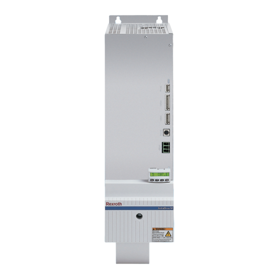
REXROTH IndraDrive C Manuals
Manuals and User Guides for REXROTH IndraDrive C. We have
1
REXROTH IndraDrive C manual available for free PDF download: Project Planning Manual
REXROTH IndraDrive C Project Planning Manual (306 pages)
Drive System
Brand:
REXROTH
| Category:
DC Drives
| Size: 8.08 MB
Table of Contents
Table of Contents
3
1 Introduction
11
About this Documentation
11
Reference Documentations - Overview
13
Box with Project Planning Manuals on Rexroth Indradrive
14
Standards
14
Your Feedback
14
Overview and Contents of the Documentations on the Drive System Rexroth Indradrive
15
Introducing the System
17
Drive System Rexroth Indradrive C
17
Drive System Rexroth Indradrive M
18
System Elements - Components of the System
18
Differences between Rexroth Indradrive C and Rexroth Indradrive M
20
Combination of Rexroth Indradrive C and Rexroth Indradrive M
21
Basic Design of the Devices
22
Basic Design of Drive Controllers
22
Available Type Currents and Performances
24
Selecting the Drive Controllers
24
Selecting the Component for Mains Supply
25
2 Important Directions for Use
27
Appropriate Use
27
Introduction
27
Areas of Use and Application
28
Inappropriate Use
28
3 Safety Instructions for Electric Drives and Controls
29
Introduction
29
Explanations
29
Hazards by Improper Use
30
General Information
31
Protection against Contact with Electrical Parts
33
Protection against Electric Shock by Protective Low Voltage (PELV)
34
Protection against Dangerous Movements
35
Protection against Magnetic and Electromagnetic Fields During Operation and Mounting
37
Protection against Contact with Hot Parts
38
3.10 Protection During Handling and Mounting
38
3.11 Battery Safety
39
3.12 Protection against Pressurized Systems
39
4 Brief Description, Applications
41
Applications of the Drive System Rexroth Indradrive
41
Mains Transformers DST and DLT
41
Applications
41
Mains Filters HNF, HNK, NFE and NFD
42
Applications
42
Mains Chokes HNL01
42
Applications HNL01.1E and HNL01.1R
42
Supply Units HMV01
43
Applications
43
Drive Controllers HMS01 and HMD01
43
Control Sections CSH01, CSB01, CDB01
44
Applications
44
Drive Controllers HCS02 and HCS03
44
DC Bus Resistor Unit HLB01
45
Applications
45
4.10 Braking Resistor HLR01
46
Applications
46
4.11 DC Bus Capacitor Units HLC01
46
4.12 Motor Filters HMF01
47
Applications
47
4.13 Accessories HAS
47
4.14 Accessory HAC01
47
5 Specifications for the Components of the Drive System
49
Tests and Certifications
49
Transport and Storage
51
Transport of the Devices
51
Storage of the Devices
51
Installation Conditions
52
Ambient and Operating Conditions
52
Capacity Utilization
53
Supply Voltages
55
Control Voltage 24V Supply
55
Power Voltage Supply
56
Limited Length of Motor Power Cables
57
6 Configuration of the Drive System Rexroth Indradrive
59
Allowed Combination of Individual Components in Drive System Rexroth Indradrive
59
Allowed Combination of Range Components from Indradrive M and Indradrive C
59
Allowed Combinations with Additional Components
59
Allowed Components in Mains Connection Phase
60
Combination HMV01 with HMS/HMD (Rexroth Indradrive M)
62
Combination HCS02 with HCS02 (Rexroth Indradrive C)
64
Combination HCS03 with HCS03 (Rexroth Indradrive C)
66
Combination HCS02 with HMS / HMD (Rexroth Indradrive C with Rexroth Indradrive M)
67
Combination HCS03 with HMS / HMD
69
Combinations at Common DC Bus that Are Not Allowed
70
Allowed Combinations in Mains Connection Phase with Mains Chokes HNL, Mains Filters HNF and Mains Chokes HNK
71
Mains Connection Phase for HMV with Mains Chokes HNL and Mains Filters HNF
71
Mains Connection Phase for HCS with Mains Chokes HNL and Mains Filters HNF Resp. NFD
72
Allowed Combinations with Motor Filters HMF01
76
Drive Controllers HCS03 with HMF01
76
Combinations of Firmware, Control Section and Drive Controller
77
Combination with Other Rexroth Components
79
Combination with Components of the Control Range Rexroth Indracontrol V
79
Combinations with Components of the Drive Range Diax04
79
Selecting Connection Cables to Motor
80
Using Third-Party Motors in Drive System Rexroth Indradrive
80
7 Arranging the Components in the Control Cabinet
81
Arranging Components in Control Cabinet from Mainly Mechanical Point of View
81
Position of Normal Use and Mounting Position
81
Main Dimensions of the System Components
83
Distances for Drive Controllers
85
Boring Dimensions for the Mounting Plate
89
Arranging Components in Control Cabinet from Mainly Thermal Point of View
97
Multiple-Line Arrangement of Drive Controllers
97
Arrangement of Cooling Units
98
Arranging Components in Control Cabinet from Mainly Electrical Point of View
100
Performance-Dependent Arrangement
100
EMC Measures for Design and Installation
101
EMC-Optimal Installation in Facility and Control Cabinet
102
Connection of Motor Cable to Drive Controller
108
Ground Connections
112
Installing Signal Lines and Cables
113
Installing the 24V Supply
114
General Measures of Radio Interference Suppression for Relays, Contactors, Switches, Chokes, Inductive Loads
115
8 Electromagnetic Compatibility (EMC)
117
Ensuring the EMC Requirements
117
Noise Immunity in Drive System
118
Noise Emission of Drive System
119
Causes of Noise Emission
119
Selecting the Mains Filter
122
Protecting Mains Filters against Overload
123
Limit Value Classes to be Achieved with Mains Filters
125
Mains Filters for Supply Modules HMV01.1E and HMV01.1R with HMS01/ HMD01
125
Mains Filters for Drive Controllers HCS02
127
Mains Filters for Drive Controllers HCS03
129
9 Types of Mains Connection
131
Individual Supply
132
Individual Supply with HMV
132
Individual Supply with HCS
132
Group Supply
134
Group Supply Without DC Bus Connection of the Groups
134
Group Supply with DC Bus Connection of the Groups
136
Central Supply
138
10 Requirements to the Mains Connection
139
10.1 General Information
139
10.2 Mains Types
139
TN-S System
139
TN-C System
139
IT System
140
TT System
140
Mains with Grounded Outer Conductor (Corner Grounded Delta Mains)
141
Mains Short-Circuit Power and System Impedance - Minimum Values at Connection Point
141
Maximum Connected Load to a Mains
143
10.4 Limit Values for Interference-Free Operation at Mains
145
Mains Frequency Tolerance
145
Voltage Tolerances and Voltage Changes
145
Mains Voltage Unbalance
145
Commutation Drops
146
Short-Time Interruptions
146
Harmonics of the Mains
146
Maximum Allowed Mains Overvoltages
147
Power Factors and Emitted Mains Harmonics of the Device
150
Power Factors Cosϕ1 (DPF) and Cosϕ (TPF)
150
Harmonics Factors THD and Distortion Factor K
151
Mains Voltage Harmonics
151
10.6 Protection Systems for the Mains Connection
152
General Information
152
Fusing by Protective Grounding
152
Connecting Equipment Grounding Conductor
156
Use of Residual-Current-Operated Circuit-Breakers (RCCB, RCD) as Additional Fusing
156
Insulation Monitoring Devices
159
11 Control Circuits for the Mains Connection
161
Control Circuits for the Mains Connection - General Information
161
Possibilities of Control
161
Control Circuits for Mains Connection of Drive Controllers Rexroth Indradrive C
163
Control Via External Mains Contactor - HCS02 and HCS03
163
Control Circuits HCS02 with DC Bus Resistor Unit HLB01.1C
165
Control Circuits for Mains Connection of Supply Units Rexroth Indradrive M
167
Deceleration in the Case of Disturbed Electronic System of Drive
167
Deceleration in the Case of E-Stop or Mains Failure
167
Control by E-Stop Relay
167
Control by the Control Unit
172
Combination of Supply Unit HMV01.1 and DC Bus Resistor Unit HLB01.1D
174
12 Connections of the Components in the Drive System
177
12.1 System Connections of the Components
177
Position of System Connections
178
Ground Connection of Housing
178
Connection Point of Equipment Grounding Conductor and Equipment Grounding Connections
178
DC Bus Connection (L+, L-)
181
Control Voltage Connection (0 V, + 24 V)
184
Module Bus Connection X1
186
Motor Connection X5 and X6
186
12.2 Overall Connection Diagrams of the System
187
13 Fusing and Selecting the Mains Contactor
189
Fusing and Selecting the Mains Contactor for Mains Connection
189
Fusing Branches Within the Control Cabinet
195
14 Accessories in the Drive System Rexroth Indradrive
197
14.1 Overview of HAS Accessories
197
14.2 Basic Accessories HAS01
199
Type Code
199
Applications
200
Scope of Supply
201
14.3 Shield Connection HAS02
223
Type Code
223
Applications
224
Scope of Supply
225
Mounting the HAS02 Accessories
234
Shield Connection of Motor Cable Via Mains Filter
238
14.4 Control Cabinet Adapter HAS03
241
Type Code
241
Applications
242
Scope of Supply
242
Advertisement
Advertisement
Related Products
REXROTH IndraDrive
Rexroth IndraDrive Mi
REXROTH IndraDrive M
REXROTH IndraControl L25 Series
REXROTH IndraControl L25 CML...PN Series
Rexroth IndraDyn A Series
REXROTH IndraDrive C Series
REXROTH DOK-MOTOR*-ADF******** -IT01-EN-P Series
REXROTH DIAX04
REXROTH DOK-DIAX04-ELS-06VRS**-WA01-EN-P Series
REXROTH Categories
Controller
Engine
DC Drives
Media Converter
Control Unit
More REXROTH Manuals
Login
Sign In
OR
Sign in with Facebook
Sign in with Google
Upload manual
Upload from disk
Upload from URL