Table of Contents
Advertisement
Quick Links
Advertisement
Table of Contents

Related Manuals for YSI 556 MPS


Summary of Contents for YSI 556 MPS
- Page 1 YSI 556 MPS Set-up, Operation & Calibration...
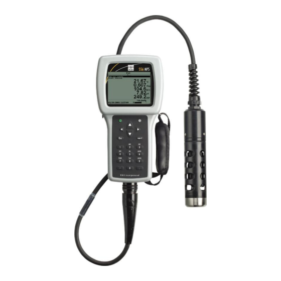
- Page 2 YSI 556 MPS The YSI 556 is just one of the instruments included in the Environment Agency UK Framework agreement. The YSI 556 is a field rugged and reliable Multi-Probe System that combines the versatility of an easy-to-use, easy-to-read handheld unit with all the functionality of a multi-parameter system.
- Page 3 YSI 556 Key Features Field rugged case, Stores 49,000 data sets, waterproof to IP67 time and date stamped Simultaneous display of all data Three-year meter warranty Rugged Probe Guard Field replaceable electrodes Standard RS232, DO cap compatible with Ecowatch membranes...
-
Page 4: Optional Features
Optional Features Optional internal barometer (user calibrated and displayed along with other data, used in dissolved oxygen calibrations, and logged to memory for tracking changes in barometric pressure. 5083 Optional flow cell 6094 Rechargeable battery back kit 5085 Hand-free harness 616 Cigarette lighter charger kit 6081 Large carrying case, hard-sided 5065 Form fitted carrying case... - Page 5 YSI 556 MPS SET-UP...
- Page 6 Inserting 4 C Batteries • Loosen the four screws in the battery lid. • Remove the battery lid. • Insert four C batteries between the clips following the polarity (+ and -) labels on the bottom of the battery compartment. •...
- Page 7 Inserting Rechargeable Battery Pack • Loosen the four screws in the battery lid on the back of the instrument using any screwdriver. • Remove the C battery lid and store for future use. Remove C batteries, if installed. • Check for proper placement of gasket on the rechargeable battery pack and lid.
- Page 8 Charging 5096 Rechargeable Battery Pack • Attach the charger adapter cable (YSI 6119) to the instrument. • Insert the barrel connector of the wall power supply into the barrel of the adapter cable. • Plug the wall power supply into an...
-
Page 9: Setting Display Contrast
Setting Display Contrast • Press and hold down the backlight key in the upper right corner of the keypad and press the “up” arrow to increase (darken) the contrast. • Press and hold down the backlight key in the upper right corner of the keypad and press the “down”... -
Page 10: Screen Features
Screen Features Main display Status bar Barometer reading (optional). Updated in real time, not corrected to sea level. Battery charge, pulsing indicates that battery is charging, flashing indicates that batteries almost exhausted. Current time Current date... -
Page 11: Keypad Features
Keypad Features Backlight / Contrast On/Off Key Arrows Keys Escape Key - Use to return to previous position in menu Enter Key Alpha/Numeric Keys - Used to enter letters and numbers Period/Decimal Point Key Minus/Hyphen (-) Key... - Page 12 L o g O n e S a m p l e R u n S t a r t L o g g i n g T e m p e r a t u r e S p e c i f i c C o n d u c t a n c e C o n d u c t i v i t y R e s i s t i v i t y...
- Page 13 YSI 556 MPS SENSORS...
- Page 14 YSI 5563 Probe Module Strain Relief Cable Metal Probe Dissolved Connector Nut Oxygen (DO) Probe pH/ORP Probe Conductivity / Transport / Temperature Calibration Probe Probe Sensor Guard...
-
Page 15: Installing The Sensors
Sensor nut O-Rings • Be sure that the probe module sensor is free of moisture and the insert the sensor. • Screw down the sensor nut using the YSI tool. Do not overtighten. - Page 16 Install DO Membrane A new membrane cap must be installed before the first use. • Unscrew and remove the probe sensor guard. • Unscrew, remove, and discard the old membrane cap. • Thoroughly rinse the sensor tip with distilled water. •...
-
Page 17: Enable Sensors
Enable Sensors • Press the On/Off key to display the Run screen. • Press the Escape key to display the main menu screen • Use the arrow keys to highlight the Sensor selection. • Press the Enter key to display the sensors enabled screen... - Page 18 Change Report • Press the On/off key to display the run screen. • Press the Escape key to display the main menu screen. • Use the arrow keys to highlight the Report selection. • Press the Enter key to display the report setup screen.
- Page 19 View all Parameters...
- Page 20 YSI 556 MPS CALIBRATION...
-
Page 21: Calibration Tips
Calibration Tips • Ensure Transport/Calibration Cup is loose to allow pressure equilibration before calibration. • The key to successful calibration is to ensure that the sensors are completely submersed. • For maximum accuracy, use a small amount of previously used calibration solution to pre-rinse the probe module. - Page 22 Accessing the Calibration Mode • Press the On/off key to display the run screen. • Press the Escape key to display the main menu screen. • Use the arrow keys to highlight the Calibration selection. • Press the Enter key to display the Calibration screen.
- Page 23 Conductivity • Use the arrow keys to highlight the Conductivity selection. • Press Enter. The Conductivity Calibration Selection Screen is displayed. • Use the arrow keys to highlight the Specific Conductance selection. • Press Enter. The Conductivity Calibration Entry Screen is displayed. •...
- Page 24 Conductivity • Screw the transport/calibration cup on the threaded end of the probe module and securely tighten. • Use the keypad to enter the calibration value of the standard you are using. • NOTE: Be sure to enter the value in mS/cm at 25C.
- Page 25 Conductivity • Observe the reading under Specific Conductance. When the reading shows no significant change for approximately 30 seconds, press Enter. The screen will indicate that the calibration has been accepted and prompt you to press Enter again to Continue. •...
-
Page 26: Dissolved Oxygen
Dissolved Oxygen • NOTE: The instrument must be on for at least 20 minutes to polarize the DO sensor before calibrating. • Use the arrow keys to highlight the Dissolved Oxygen selection. • Press Enter. The dissolved oxygen calibration screen is displayed. •... - Page 27 Dissolved Oxygen • NOTE: Make sure that the DO and temperature sensors are not immersed in the water. • Engage only 1 or 2 threads of the transport/calibration cup to ensure the DO sensor is vented to the atmosphere. • Use the keypad to enter the current local barometric pressure.
- Page 28 Dissolved Oxygen • Allow approximately ten minutes for the air in the transport/calibration cup to become water saturated and for the temperature to equilibrate before proceeding. The current values of all enabled sensors will appear on the screen and will change with time as they stabilize. •...
- Page 29 • Use the arrow keys to highlight the pH selection. • Press Enter. The pH calibration screen is displayed. – Select the 1-point option only if you are adjusting a previous calibration. – Select the 2-point option to calibrate the pH sensor using only two calibration standards.
- Page 30 • Use the keypad to enter the calibration value of the buffer you are using at the current temperature. (check YSI bottles) • Press Enter. The pH calibration screen is displayed.
- Page 31 • Allow at least one minute for temperature equilibration before proceeding. • When the reading shows no significant change for approximately 30 seconds, press Enter. The screen will indicate that the calibration has been accepted and prompt you to press Enter again to Continue.
- Page 32 • Use the arrow keys to highlight the ORP selection. Press Enter. The ORP calibration screen is displayed. • Place the correct amount of a known ORP solution (we recommend Zobell solution) into a clean, dry or pre-rinsed transport/calibration cup. •...
- Page 33 • NOTE: Verify that the temperature reading matches the value you used in . • Observe the reading under ORP, when the reading shows no significant change for approximately 30 seconds, press Enter. The screen will indicate that the calibration has been accepted and prompt you to press Enter again to Continue.
-
Page 34: Return To Factory Settings
Return to Factory Settings • NOTE: We will use the Conductivity sensor as an example; however, this process will work for any sensor. • Press Enter. The Conductivity Calibration Selection Screen is displayed. • Use the arrow keys to highlight the Specific Conductance selection. - Page 35 YSI 556 MPS...
-
Page 36: Real-Time Data
Real-Time Data • Press the On/off key or select Run from the main menu to display the run screen. • Make sure the probe sensor guard is installed. • Place the probe module in the sample. Be sure to completely immerse all the sensors. •... - Page 37 YSI 556 MPS FILE...
- Page 38 File • Press the On/off key to display the run screen. • Press the Escape key to display the main menu screen. • Use the arrow keys to highlight the File selection. • Press the Enter key. The file screen is displayed.
- Page 39 Directory • Use the arrow keys to highlight the Directory selection. • Press the Enter key. The file list screen is displayed. • NOTE: Files are listed in the order in which they are logged to memory. Sample Data files have the file extension .dat, while Calibration Record files have the file extension .glp.
-
Page 40: View File
View File • Use the arrow keys to highlight the View file selection. • Press the Enter key. A list of files is displayed. • Use the arrow keys to highlight an individual file. • NOTE: You may have to scroll down to see all the files. -
Page 41: Upload Data To Pc
• Disconnect the YSI 5563 Probe Module from the YSI 556 MPS instrument. • Connect the YSI 556 MPS to a serial (Comm) port of your computer via the 655173 PC Interface cable as shown in the following diagram: •... - Page 42 • Use the arrow keys to highlight the DAT file that you wish to transfer and press Enter, both the YSI 556 MPS and PC displays show the progress of the file transfer. • After transfer, the file will be located in the C:\ECOWWIN\DATA folder of your PC, designated with a .DAT extension.
- Page 43 Binary, Comma & “” Delimited, and ASCII Text. • Choose an option and press Enter, both the YSI 556 and PC displays show the progress of the file transfer. • NOTE: To view the Calibration Record data after upload, simply open the .txt file in a...
- Page 44 Exporting .DAT File in Excel Ecowatch for Windows • Open .dat file by pressing File..Open..(desired file name). • After file has opened click File..Export..DBF MS Excel • Open .dbf file by pressing File..Open..(desired file name.dbf) • ENSURE TO SELECT ALL FILES OPTION •...
- Page 45 YSI 556 MPS LOGGING...
-
Page 46: Logging Set Up
Logging Set up • Press the On/off key to display the run screen. • Press the Escape key to display the main menu screen. • Use the arrow keys to highlight the Logging setup selection. • Press the Enter key. The logging setup screen is displayed –... - Page 47 Site List • Use the arrow keys to highlight the Use site list selection. • Press the Enter key. A check mark is entered in the box next to the use site list selection and two new entries appear on the logging setup screen. •...
- Page 48 Site List • Press the Enter key. The edit site list screen is displayed. See . The Filename field is ready for input. • Use the keypad to enter a filename up to 8 characters in length. • Press the Enter key. The cursor moves to the right for the entry of a Site name.
-
Page 49: Logging Data Without A Site List
Logging Data Without a Site List • Use the arrow keys to highlight the Log one sample selection on the run screen if only a single sample is being logged. • OR Use the arrow keys to highlight the Start logging selection on the run screen if a data stream is being logged. - Page 50 Logging Data Without a Site List • Use the keypad to enter a site description name. • Press the Enter key to input the site description. • NOTE: If you want to change the logging setup, such as sampling interval or storing the barometer reading, use the arrow keys to highlight the Configure field, press the Enter key.
-
Page 51: Logging Data With A Site List
Logging Data With a Site List • Use the arrow keys to highlight the Log one sample selection on the run screen if only a single sample is being logged. • OR Use the arrow keys to highlight the Start logging selection on the run screen if a data stream is being logged. - Page 52 YSI 556 MPS SYSTEM SET-UP...
- Page 53 System Set-Up • Time / date • Data filters • Shut off time • Comma radix • • GLP filename • Barometer units • Calibrate Barometer...
-
Page 54: Calibrate Barometer
Calibrate Barometer • Determine your local barometric pressure from an independent laboratory barometer or from your local weather service. • If the barometric pressure (BP) reading is from your local weather station, reverse the equation that corrects it to sea level. •... -
Page 55: Maintenance
YSI 556 MPS MAINTENANCE... -
Page 56: Dissolved Oxygen
Dissolved Oxygen For best results, we recommend that the KCl solution and the membrane cap be changed at least once every 30 days. • The rate of stirring should be at least 1 foot per second. • Membrane life depends on usage. Erratic readings are a result of loose, wrinkled, damaged, or fouled membranes, or from large (more than 1/8"... - Page 57 Dissolved Oxygen • It is possible for the silver anode, which is the entire silver body of the sensor, to become contaminated. This will prevent successful calibration. • For correct sensor operation, the gold cathode must always be bright. If it is tarnished (which can result from contact with certain gases), or plated with silver (which can result from extended use with a loose or wrinkled membrane), the gold surface must be restored.
- Page 58 Silver Anode Cleaning – After extended use, a thick layer of AgCl builds up on the silver anode reducing the sensitivity of the sensor. The anode must be cleaned to remove this layer and restore proper performance. The cleaning can be chemical or mechanical: –...
- Page 59 YSI 5238 Probe Reconditioning Kit. – Using the sanding paper provided in the YSI 5238 Probe Reconditioning Kit, wet sand the gold with a twisting motion about 3 times or until all silver deposits are removed and the gold appears to have a matte finish.
- Page 60 Initially, simply use clean water and a soft clean cloth, lens cleaning tissue, or cotton swab to remove all foreign material from the glass bulb (YSI 5564 and YSI 5565) and platinum button (YSI 5565). Then use a moistened cotton swab to carefully remove any material that may be blocking the reference electrode junction of the sensor.
- Page 61 pH / ORP (Stage 2) • NOTE: If good pH and/or ORP response is still not restored by the above procedure, perform the following additional procedure: • Soak the sensor for 30-60 minutes in one molar (1 M) hydrochloric acid (HCl). This reagent can be purchased from most distributors.
- Page 62 pH / ORP (Stage 3) • NOTE: If biological contamination of the reference junction is suspected or if good response is not restored by the above procedures, perform the following additional cleaning step: • Soak the sensor for approximately 1 hour in a 1 to 1 dilution of commercially available chlorine bleach.
- Page 63 The single most important requirement for accurate and reproducible results in conductivity measurement is a clean cell. A dirty cell will change the conductivity of a solution by contaminating it. The small cleaning brush included in the YSI 5511 Maintenance Kit is ideal for this purpose.
- Page 64 YSI 556 MPS STORAGE...
-
Page 65: Short-Term Storage
Immersing them could cause some of them to drift or result in a shorter lifetime. – YSI recommends that short term storage of all multi-parameter instruments be done by placing approximately 1/2 inch of tap water in the transport/calibration cup that was supplied with the instrument, and by placing the probe module with all of the sensors installed into the cup. -
Page 66: Long Term Storage
Long Term Storage • Remove the pH or pH/ORP sensor from the probe module and store according to the individual sensor storage instructions. • Seal the empty port with the provided port plug. • NOTE: Leave the conductivity/temperature sensor and dissolved oxygen sensor, with membrane cap still on, in the probe module. - Page 67 Long Term Storage • pH and Combination pH/ORP Sensor – The key to sensor storage is to make certain that the reference electrode junction does not dry out. Junctions which have been allowed to dry out due to improper storage procedures can usually be rehydrated by soaking the sensor for several hours (overnight is recommended) in a solution which is 2 molar in potassium chloride.
- Page 68 Thank you…. Please visit the YSI website on WWW.YSI.COM...
Need help?
Do you have a question about the 556 MPS and is the answer not in the manual?
Questions and answers