Table of Contents
Advertisement
Quick Links
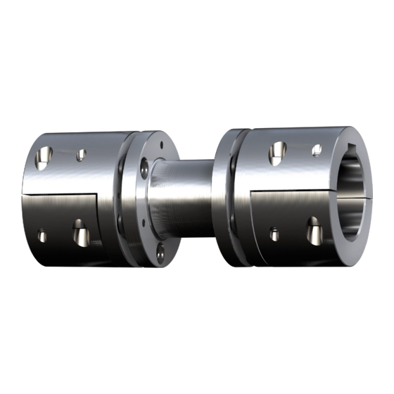
RIGIFLEX
Torsionally stiff steel lamina
coupling
according to directive 2014/34/EU
and UK directive
SI 2016 No. 1107
Please observe protection
note ISO 16016.
RIGIFLEX
Operating/Assembly instructions
®
-N
Drawn:
2022-07-06 Pz/Wb
Verified:
2022-08-09 Pz
®
-N
Type A, size 35
Type A, size 50 - 408
Type A-J
Replacing:
Replaced by:
KTR-N
47410 EN
Sheet:
1 of 24
Edition:
14
KTR-N dated 2019-11-05
Advertisement
Table of Contents

Related Manuals for KTR-Group RIGIFLEX-N


Summary of Contents for KTR-Group RIGIFLEX-N
- Page 1 KTR-N 47410 EN ® RIGIFLEX Sheet: 1 of 24 Operating/Assembly instructions Edition: ® RIGIFLEX Torsionally stiff steel lamina coupling Type A, size 35 according to directive 2014/34/EU and UK directive SI 2016 No. 1107 Type A, size 50 - 408 Type A-J Drawn: 2022-07-06 Pz/Wb...
-
Page 2: Table Of Contents
KTR-N 47410 EN ® RIGIFLEX Sheet: 2 of 24 Operating/Assembly instructions Edition: ® RIGIFLEX -N is a torsionally stiff flexible steel laminae coupling. It is able to compensate for shaft misalignment, for example caused by thermal expansion, etc. Table of contents Technical data Advice General advice... -
Page 3: Technical Data
KTR-N 47410 EN ® RIGIFLEX Sheet: 3 of 24 Operating/Assembly instructions Edition: Technical data ® Illustration 1: RIGIFLEX -N type A, size 35 ® Illustration 2: RIGIFLEX -N type A, size 50 - 408 Table 1: Dimensions - type A Dimensions [mm] Max. - Page 4 KTR-N 47410 EN ® RIGIFLEX Sheet: 4 of 24 Operating/Assembly instructions Edition: Technical data ® Illustration 3: RIGIFLEX -N, type A-J Table 2: Dimensions - type A-J Max. finish bore [mm] Setscrew Size 40/90 Dimensions [mm] Size DBSE 63.0 72.5 83.0 87.5 1) Other shaft distance dimensions available on request...
-
Page 5: Advice
KTR-N 47410 EN ® RIGIFLEX Sheet: 5 of 24 Operating/Assembly instructions Edition: Advice 2.1 General advice Read through these operating/assembly instructions carefully before you start up the coupling. Pay special attention to the safety instructions! ® The RIGIFLEX -N coupling is suitable and approved for the use in potentially explosive atmospheres. -
Page 6: Intended Use
KTR-N 47410 EN ® RIGIFLEX Sheet: 6 of 24 Operating/Assembly instructions Edition: Advice 2.4 Intended use You may only assemble, operate and maintain the coupling if you • have carefully read through the operating/assembly instructions and understood them • are technically qualified and specifically trained (e. g. safety, environment, logistics) •... -
Page 7: Transport And Packaging
KTR-N 47410 EN ® RIGIFLEX Sheet: 7 of 24 Operating/Assembly instructions Edition: Storage, transport and packaging 3.2 Transport and packaging In order to avoid any injuries and any kind of damage always make use of proper transport and lifting equipment. The couplings are packed differently each depending on size, number and kind of transport. -
Page 8: Advice For Finish Bore
KTR-N 47410 EN ® RIGIFLEX Sheet: 8 of 24 Operating/Assembly instructions Edition: Assembly 4.1 Components of the coupling ® Components of RIGIFLEX -N type A-J Component Quantity Description Coupling hub Coupling hub J Spacer complete see table 5 Cap screws DIN EN ISO 4762 see table 5 Cap screws DIN EN ISO 4762 see table 5... - Page 9 KTR-N 47410 EN ® RIGIFLEX Sheet: 9 of 24 Operating/Assembly instructions Edition: Assembly 4.2 Advice for finish bore Type A, size 35 Type A, size 50 - 408 Type A-J, component 1.1 Type A-J, component 1.2 Illustration 6: Concentricity and axial runout The customer bears the sole responsibility for all machining processes performed subsequently on unbored or pilot bored as well as finish machined coupling components and spare parts.
-
Page 10: Assembly Of Coupling Hubs
KTR-N 47410 EN ® RIGIFLEX Sheet: 10 of 24 Operating/Assembly instructions Edition: Assembly 4.3 Assembly of coupling hubs We recommend to inspect bores, shaft, keyway and feather key for dimensional accuracy before assembly. Heating the hubs lightly (approx. 80 °C) allows for an easier mounting on the shafts. Pay attention to the ignition risk in potentially explosive atmospheres! Touching the heated hubs causes burns. -
Page 11: Assembly Of The Spacer
KTR-N 47410 EN ® RIGIFLEX Sheet: 11 of 24 Operating/Assembly instructions Edition: Assembly 4.4 Assembly of the spacer If the coupling is supplied with a transportation lock (optionally), the following has to be observed: The spacer sleeves (steel) have to be removed for further assembly and operation (see illustration 8). - Page 12 KTR-N 47410 EN ® RIGIFLEX Sheet: 12 of 24 Operating/Assembly instructions Edition: Assembly 4.4 Assembly of the spacer • With assembly-balanced couplings make sure that the balancing marking X (Y) of the hub is flush with the balancing marking X (Y) of the spacer (see illustration 11) (optionally). •...
-
Page 13: Displacements - Alignment Of The Couplings
KTR-N 47410 EN ® RIGIFLEX Sheet: 13 of 24 Operating/Assembly instructions Edition: Assembly 4.5 Displacements - alignment of the couplings The displacement figures specified in table 11 provide for sufficient safety to compensate for external influences like, for example, thermal expansion or foundation settling. In order to ensure a long service life of the coupling and avoid hazards with the use in potentially explosive atmospheres, the shaft ends must be accurately aligned. -
Page 14: Start-Up
KTR-N 47410 EN ® RIGIFLEX Sheet: 14 of 24 Operating/Assembly instructions Edition: Assembly 4.5 Displacements - alignment of the couplings Table 11: Displacement figures Radial displacement Axial Angular K displacement displacement Size [mm] K K [mm] [°] DBSE = 100 DBSE = 140 DBSE = 180 DBSE = 200... - Page 15 KTR-N 47410 EN ® RIGIFLEX Sheet: 15 of 24 Operating/Assembly instructions Edition: Start-up Please check if a proper enclosure (ignition protection, coupling protection, contact protection) has been mounted and the operation of the coupling is not affected by the enclosure. The same applies for test runs and rotational direction inspections.
-
Page 16: Breakdowns, Causes And Elimination
KTR-N 47410 EN ® RIGIFLEX Sheet: 16 of 24 Operating/Assembly instructions Edition: Breakdowns, causes and elimination ® The below-mentioned failures can result in an improper use of the RIGIFLEX -N coupling. In addition to the specifications given in these operating/assembly instructions make sure to avoid such failures. The errors listed can only be clues to search for the failures. -
Page 17: Disposal
KTR-N 47410 EN ® RIGIFLEX Sheet: 17 of 24 Operating/Assembly instructions Edition: Breakdowns, causes and elimination Hazard notes for Breakdowns Causes potentially explosive Elimination atmospheres 1) Set the unit out of operation 2) Disassemble the coupling and remove remainders of the spacer Fracture of steel Operating error of the 3) Inspect coupling components and replace... -
Page 18: Maintenance And Service
KTR-N 47410 EN ® RIGIFLEX Sheet: 18 of 24 Operating/Assembly instructions Edition: Maintenance and service Monitoring of the general condition of the coupling can be done both at standstill and during operation. If the coupling is tested during operation, the operator must ensure an appropriate and proven test procedure (e. g. stroboscopic lamp, high-speed camera, etc.) which is definitely comparable to testing at standstill. -
Page 19: Enclosure A
KTR-N 47410 EN ® RIGIFLEX Sheet: 19 of 24 Operating/Assembly instructions Edition: Enclosure A Advice and instructions regarding the use in potentially explosive atmospheres Types available: Type A ® RIGIFLEX -N with spacer made of steel only. 10.1 Intended use in potentially explosive atmospheres Conditions of operation in potentially explosive atmospheres... -
Page 20: Inspection Intervals For Couplings In
KTR-N 47410 EN ® RIGIFLEX Sheet: 20 of 24 Operating/Assembly instructions Edition: Enclosure A Advice and instructions regarding the use in potentially explosive atmospheres 10.1 Intended use in potentially explosive atmospheres 2. Mining Equipment group I of category M2 (coupling is not approved/not suitable for equipment group M1). Permissible ambient temperature -40 °C to +130 °C. - Page 21 KTR-N 47410 EN ® RIGIFLEX Sheet: 21 of 24 Operating/Assembly instructions Edition: Enclosure A Advice and instructions regarding the use in potentially explosive atmospheres 10.3 marking of coupling for potentially explosive atmospheres ® The explosion protection marking of the RIGIFLEX -N coupling is applied on the outer sheath or on the front side.
- Page 22 KTR-N 47410 EN ® RIGIFLEX Sheet: 22 of 24 Operating/Assembly instructions Edition: Enclosure A Advice and instructions regarding the use in potentially explosive atmospheres 10.3 marking of coupling for potentially explosive atmospheres Comments on marking Equipment group I Mining Equipment group II Non-mining Equipment category 2G Equipment ensuring a high level of safety, suitable for zone 1...
-
Page 23: Eu Declaration Of Conformity
KTR-N 47410 EN ® RIGIFLEX Sheet: 23 of 24 Operating/Assembly instructions Edition: Enclosure A Advice and instructions regarding the use in potentially explosive atmospheres 10.4 EU Declaration of conformity EU Declaration of Conformity resp. Certificate of Conformity corresponding to EU directive 2014/34/EU dated 26 February 2014 and to the legal regulations adopted for its implementation The manufacturer - KTR Systems GmbH, Carl-Zeiss-Str. -
Page 24: Declaration Of Conformity
KTR-N 47410 EN ® RIGIFLEX Sheet: 24 of 24 Operating/Assembly instructions Edition: Enclosure A Advice and instructions regarding the use in potentially explosive atmospheres 10.5 UK Declaration of conformity UK Declaration of Conformity resp. Certificate of Conformity corresponding to UK directive SI 2016 No. 1107 dated 26 February 2014 and to the legal provisions adopted for its implementation The manufacturer - KTR Systems GmbH, Carl-Zeiss-Str.
Need help?
Do you have a question about the RIGIFLEX-N and is the answer not in the manual?
Questions and answers