Table of Contents
Advertisement
Quick Links
Advertisement
Table of Contents

Related Manuals for Keysight Technologies L7222C


Summary of Contents for Keysight Technologies L7222C
- Page 1 Keysight L7222C Coaxial Transfer Switch Operating and Service Manual...
- Page 2 FAR 27.401 or DFAR could result in personal injury or death. 227.7103-5 (c), as applicable in any Do not proceed beyond a WARNING technical data. notice until the indicated conditions are fully understood and met. Keysight L7222C Operating and Service Manual...
-
Page 3: Waste Electrical And Electronic Equipment (Weee) Directive
To contact Keysight for sales and technical support, refer to the support links on the following Keysight websites: – www.keysight.com/find/switches (product-specific information and support, software and documentation updates) – www.keysight.com/find/assist (worldwide contact information for repair and service) Keysight L7222C Operating and Service Manual... - Page 4 THIS PAGE HAS BEEN INTENTIONALLY LEFT BLANK. Keysight L7222C Operating and Service Manual...
-
Page 5: Table Of Contents
......... . .12 Keysight L7222C Operating and Service Manual... - Page 6 THIS PAGE HAS BEEN INTENTIONALLY LEFT BLANK. Keysight L7222C Operating and Service Manual...
-
Page 7: List Of Figures
List of Figures Figure 1 L-series coaxial transfer switch - L7222C ... 1 Figure 2 Keysight L7222C coaxial transfer switch schematic . . . 4 Figure 3 (a) RF port connections and (b) drive connections . - Page 8 Keysight L7222C Operating and Service Manual...
-
Page 9: List Of Tables
List of Tables Table 1 General information on L7222C coaxial transfer switch Table 2 Standard drive control ......4... - Page 10 THIS PAGE HAS BEEN INTENTIONALLY LEFT BLANK. Keysight L7222C Operating and Service Manual...
-
Page 11: General Information
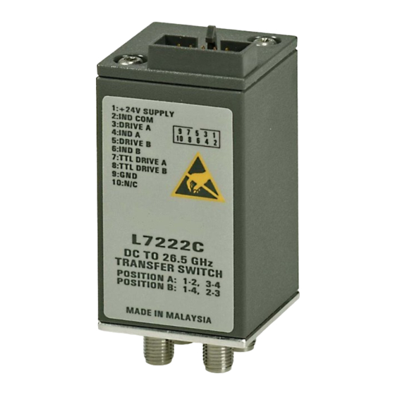
General Information L-Series coaxial transfer switch overview Keysight L7222C coaxial transfer switch is designed for flexibility in signal routing applications and provides exceptional insertion loss repeatability of 0.03 dB, low insertion loss and high isolation > 80 dB. Figure 1... -
Page 12: Features
– Magnetic latching – TTL/5V CMOS compatible (optional) The L7222C can be used in a variety of applications such as switching two inputs and two outputs, signal reversal switching or as a drop-out switch. Innovative design and careful process control mean the L7222C meet the requirements for highly repeatable switching elements in test instruments and switching interfaces. -
Page 13: Features
The longevity of these switches increases system uptime, and lowers the cost of ownership by reducing calibration cycles and switch maintenance. Keysight L7222C Operating and Service Manual... -
Page 14: Driving The Switch
Figure 2 Keysight L7222C coaxial transfer switch schematic Driving the switch There are two positions for the L7222C coaxial transfer switch. See Figure Position A has RF Port 1 connected to RF Port 2 and RF Port 3 connected to RF Port 4. -
Page 15: Standard Drive
Therefore, if a pulse drive is used and continuous indicator operation is required, pin 9 must be grounded. – Select position A by applying ground to pin 3. – Select position B by applying ground to pin 5. Keysight L7222C Operating and Service Manual... -
Page 16: Single Line Ttl Drive
For TTL drive, pin 9 must be grounded. NOTE In addition to the quiescent current supplying the electronic position-sensing circuitry, the drive current flows out of pin 9 (during switching) when using TTL drive. Keysight L7222C Operating and Service Manual... -
Page 17: Electronic Position Indicators
1 but requires that pin 9 be grounded if pulse drive is used and continuous indicators operation is desired. If pin 9 is not grounded, the position indicators will function while the appropriate drive has ground applied. Figure 4 Pin function diagram for indicator Keysight L7222C Operating and Service Manual... -
Page 18: Installation
Sales and Technical Support in the front matter of this manual for the Keysight Technologies nearest you. Attach a tag indicating the type of service required, return address, model number, and serial number. Mark the container FRAGILE to insure careful handling. In any correspondence, refer to the instrument by model number and serial number. -
Page 19: Operating Instruction
The s-parameters measurement is the best way to determine if the switch is working properly. Keysight transfer switch Figure 5 Connection to perform quick check Keysight L7222C Operating and Service Manual... - Page 20 6 Now, still in position B, disconnect switch’s Port 1 and Port 2 from network analyzer. Then, connect network analyzer’s Port 1 and Port 2 to Port 2 and Port 3 of the switch. Measure S11, S21 and S22 and verify against specifications. Keysight L7222C Operating and Service Manual...
-
Page 21: Performance Tests
The coaxial transfer switch can be tested to the accuracy of the specifications with a network analyzer or equivalent equipment of suitable accuracy. If a network analyzer is available, test the instrument using the procedure in the analyzer’s operating manual. Keysight L7222C Operating and Service Manual... -
Page 22: Service Instructions
The coaxial transfer switch does not have internal adjustments and should not be opened. Repair The L7222C coaxial transfer switch is not recommended for repair as most components are not easily removed. Maintenance The connectors, particularly the connector faces, must be kept clean. For instruction on connecting and care of your connectors, refer to the Microwave Connector Care Quick Reference Card (08510-90360). - Page 23 This information is subject to change without notice. Always refer to the English version at the Keysight website for the latest revision. © Keysight Technologies 2007 - 2019 Edition 3, March 28, 2019 Printed in Malaysia *L7222-90001* L7222-90001...
Need help?
Do you have a question about the L7222C and is the answer not in the manual?
Questions and answers