
Related Manuals for KBR multicount D5-0-LCD-1DO-3P-75A-MID


Summary of Contents for KBR multicount D5-0-LCD-1DO-3P-75A-MID
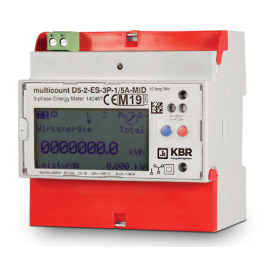
- Page 1 Quick guide Technical parameters MID-Counter multicount D5-0-LCD-1DO-3P-75A-MID multicount D5-0-LCD-1DO-3P-1/5A-MID multicount D5-2-LCD-ES-4DO-3P-75A-MID multicount D5-2-LCD-ES-4DO-3P-1/5A-MID...
-
Page 2: Table Of Contents
Disclaimer . . . . . . . . . . . . . . . . . . . . . . . . . . . . .5 Configuration of relay-output . - Page 3 Dear customer Thank you for choosing a KBR product . To familiarize yourself with the operation and configuration of the device, we recommend that you read this manual carefully . This will enable you to make use of the full range of functions that this high-quality product has to offer.
- Page 4 This manual contains notes that must be observed for your personal safety and to prevent damage to the equipment . These notes are identified by a warning sign or information symbol, depending on the degree of hazard they warn about . DANGEROUS VOLTAGE This means that death, serious physical injury or considerable property damage will occur if the appropriate safety precautions are not taken .
-
Page 5: Disclaimer
DISCLAIMER The contents of this document have been checked using the hardware and software described . However, deviations cannot be ruled out, meaning that no guarantee can be made for complete agreement . The information provided in this manual is checked on a regular basis; any corrections necessary will be included in the next revision . - Page 6 DANGEROUS VOLTAGE The applicable DIN/VDE regulations must be observed during installation! Connection to the mains, commissioning and operation of the device may only be carried out by qualified personnel. Qualified personnel as defined in the safety instructions in this user manual are personnel with electrical engineering qualifications, knowledge of the national accident prevention regulations and safety engineering standards as well as of the installation, commissioning and operation of the device .
- Page 7 To ensure proper and safe operation of the device, ensure that it is transported, stored, installed, assembled, and carefully operated and maintained in accordance with the specifications. If the device has any visible damage it is considered unfit for use and must be disconnected from the power supply! Troubleshooting, repairs and maintenance work may only be carried out at our plant or after contacting our customer service team .
- Page 8 NOTE Der multicount D5-0-LCD-MID-1 / multicount D5-2-LCD-MID-1 is maintenance free . In case of damage (for example shipping, incorrect connection or storage) repairs may only be done by KBR GmbH .
-
Page 9: Product Liability
Product liability You have purchased a high-quality product. Only components of the highest quality and maximum reliability are used . Each device is subject to long-term testing before delivery . For details on product liability, please refer to our general terms and conditions for electronic equipment . -
Page 10: Menu Navigation
MENU NAVIGATION Blue Go to next unit Active energy, active power etc . More information of unit E . g . phase L1, L2, L3, total, Min . / Max values Yellow Service key, on the right side bellow the red terminal cover . To save a configuration, push the service key for 5 seconds. -
Page 11: Technical Data
TECHNICAL DATA Nominal voltage U 3x230/400V (+/- 20%) Accuracy class B (1%) Nominal frequency f 50Hz (60Hz on request) Operating temperature -25° C…+55° C Storage temperature -30° C…+70° C Protection class Clamps: IP20 Case: IP51 Mechnanical: Electro-magnetic: Safety class Description 3-phase static Energy and Power Meter EC-type examination CH-MI003-13022... -
Page 12: Direct Connection
Direct connection Current (I 0 . 0 2 A / 0 . 2 5 A / 0 . 5 A / 5 A / 75 A (5(75)) Current transformer /5A und /1A Current /5A (I 0 . 0 1 A / 0 . 0 5 A / 0 . 2 5 A / 5 A / 6 A (5(6)) Current /1A (I 0 . -
Page 13: Cable Requirement >65A
Cable requirement >65A Type: Wire (Cu), cross-section: 35mm², Outside-Ø 9,55 mm DISPLAY LANGUAGE Display language can be selected between English and German (Deutsch) . Configure of display language 1) Blue key to Adjustments 2) Red key to Language (Sprache) 3) Push Service-Key briefly 4) Adjust Language by blue key 5) Saving: Push Service key for 5 seconds, until the display stops to flash... -
Page 14: Tariff Control
TARIFF CONTROL Tariff changeover works with a 230V signal. Neutral cond. on clamp 5 (NE), outer cond . switched on clamp 3 (E3), respectively 4 (E4) . Double-tariff Four-tariff (optional) 0 = no voltage 1 = voltage... -
Page 15: Current Transformer Ratio
CURRENT TRANSFORMER RATIO Current transformer ratio can be adjusted from 5/5 to 20‘000/5A and 1/1 to 4’000/1A Left (blue) key = Change of digit / number Right (red) key = Go to next digit / number Current transformer /5A AABCC : 5A adjustable in steps of 1 adjustable in steps of 1 adjustable in steps of 5... -
Page 16: S0 Pulse-Output
6) Go to next digit by red key 7) Adjust digit by blue key 8) Go to next digit by red key . 9) Adjust next two digits by blue key . 10) Saving: Push Service key for 5 seconds, until digits are not blinking S0 pulse-output The four S0 pulse-outputs are designed according to EN62053-31 (DIN 83864). -
Page 17: Configuration Pulse Rate
Configuration pulse rate 1) Blue key to Adjustments 2) Red key to S0 Pulse Rate 3) Push service key briefly 4) Move decimal place by blue key Example 1000 . 0 00 = 1000 Impulse 5) Saving: Push Service key for 5 seconds, until digits are not blinking Configuration of pulse length 1) Blue key to Adjustments 2) Red key to S0 Pulse Duration... -
Page 18: Length
Length Adjustable from 4 to 250 milliseconds in steps of 2 ms . SWITCHING OUTPUT The S0 pulse-outputs can be configured as a relay-output. Configuration of relay-output 1)Blue key to Adjustments 2) Red key to Assignment output X 3) Push service key briefly 4) Adjust to Relay Output by blue key 5) Saving: Push Service key for 5 seconds, until digits are not blinking... -
Page 19: Peak-Control / Threshold
PEAK-CONTROL / THRESHOLD Threshold The following values can be chooses as a threshold: - Active Power - Reactive power - Apparent power - Current total - Current per phase L1 / L2 / L3 Only one threshold can be defined for all 4 outputs. Only positive values are detected . -
Page 20: Response Time / Release Time
Response time / release time The response and release time is adjustable between 0 and 9999 seconds . Response time: Time, until contact switches Release time: Time, until contact switches after threshold is not exceeded anymore . The threshold function can be assigned to any output S0 . Configuration of threshold 1) Blue key to Adjustments 2) Red key to Assignment Output X... -
Page 21: Date / Time
12) Red key to Threshold Time till ON 13) Push service key briefly 14) Adjust digit by blue key 15) Go to next digit by red key 16) Saving: Push Service key for 5 seconds, until digits are not blinking 17) Red key to Threshold Time till OFF 18) Push service key briefly 19) Adjust digit by blue key... -
Page 22: Configuration Of Time
Configuration of time 1) Blue key to Date 2) Red key to Time 3) Push service key briefly 4) Adjust first digit by red key 5) Go to next digit by red key 6) Saving: Push service key for 5 seconds Maximum active power: measurement period Configuration of measurement period 1) lue key to Adjustments... -
Page 23: Start / Synchronization
Start / synchronization measurement period Synchronization takes place by using a 230VAC control signal . In normal operation mode, voltage is connected to input E1, input E2 is dead (without voltage) . To start a new measurement period, disconnect voltage from E1 and connect voltage to E2 . -
Page 24: Reset Power Outages
Reset power outages 1) Blue key to Reset 2) Red key to Power outages 3) Push service key briefly 4) Set to RESET by blue key 5) Perform reset: Push service key for 5 seconds RESET OF TARIFF REGISTER The multicount has a resettable tariff register. The resettable register is indicated by and arrow above the unit (kWh) . -
Page 25: Error Messages
ERROR MESSAGES If an internal error appears, an error message is displayed . F . F . 0 (00000000) No error, meter ok F . F . 0 (xxxxxxx0) Meter calibrated F . F . 0 (xxxxxxx1) Meter not calibrated F . - Page 26 F . F . 0 (xxxx0xxx) Micro RAM and STACK OK F . F . 0 (xxxx1xxx) Error checksum Micro RAM . F.F.0(xxxx2xxx) Error Micro STACK (Overflow). F . F . 0 (xxxx3xxx) Error checksum Micro RAM and Error Micro STACK .
-
Page 27: Data Backup / Power Failure
DATA BACKUP / POWER FAILURE To prevent data loss in case of power failure, all relevant data are stored in non-volatile EEPROM . This takes place if voltage is falling below a defined level. Also automatically every 24 hours to save all relevant data in non-volatile EEPROM . -
Page 28: Connection-Diagram
CONNECTION-DIAGRAM control inputs 10 11 12 13 14 15 multicount D5-0-LCD-1DO-3P-1/5A-MID... - Page 29 10 11 12 13 14 15 multicount D5-0-LCD-1DO-3P-75A-MID...
- Page 30 10 11 12 13 14 15 KBR eBus RS485 multicount D5-2-LCD-ES-4DO-3P-1/5A-MID...
- Page 31 10 11 12 13 14 15 KBR eBus RS485 multicount D5-2-LCD-ES-4DO-3P-75A-MID...
- Page 32 KBR Kompensationsanlagenbau GmbH www.kbr.de Am Kiefernschlag 7 T +49 (0) 9122 6373 - 0 D-91126 Schwabach F +49 (0) 9122 6373 - 83 E info @ kbr . d e...
Need help?
Do you have a question about the multicount D5-0-LCD-1DO-3P-75A-MID and is the answer not in the manual?
Questions and answers