
Related Manuals for KBR multimess F144-0-LED 5 Series


Summary of Contents for KBR multimess F144-0-LED 5 Series
- Page 1 User manual Technical parameters Three-phase network measuring device multimess F144-0-LED-...-5 Your partner for network analysis System English...
-
Page 2: Table Of Contents
– Active energy HT/LT consumption, maximum cumulated active energy of the period ........38 10.9 kvarh - Reactive energy meter HT/ © KBR Kompensationsanlagenbau GmbH LT consumption, maximum Misprints, printing errors cumulated cycle reactive power . 40 and technical changes reserved Rev. 5.00... - Page 3 Table of contents KBR multimess F144-0-LED-...-5 10.10 THD- distortion factor and partial 12.3 Deleting extreme values ....71 harmonic content of the voltage 12.3.1 Deleting individual and current network harmonics . 42 extreme values ........71 10.11 Extra ............43 12.3.2 Deleting all extreme values ..
- Page 4 Introduction Dear customer Thank you for choosing a KBR product. To familiarize yourself with the operation and configuration of the device, we recommend that you read this manual carefully. This will enable you to make use of the full range of functions that this high-quality product has to offer.
- Page 5 Introduction KBR multimess F144-0-LED-...-5 This manual contains notes that must be observed for your personal safety and to prevent damage to the equipment. These notes are identified by a warning sign or information symbol, depending on the degree of hazard they warn about.
- Page 6 KBR multimess F144-0-LED-...-5 Introduction DANGEROUS VOLTAGE The applicable DIN/VDE regulations must be observed during installation! Connection to the mains, commissioning and operation of the device may only be carried out by qualified personnel. Qualified personnel as defined in the safety instructions in this user manual are personnel with electrical engineering...
- Page 7 Introduction KBR multimess F144-0-LED-...-5 Product liability You have purchased a high-quality product. Only components of the highest quality and maximum reliability are used. Each device is subject to long-term testing before delivery. For details on product liability, please refer to our general terms and conditions for electronic equipment.
-
Page 8: Device Memory
KBR multimess F144-0-LED-...-5 Device memory Device memory The device is equipped with internal data memory (flash). After uninterrupted charging (device connected to the power supply) for approx. 100 hours, the buffer capacitor will have sufficient charge to protect the internal clock from failure due to disconnection from the power supply for approx. -
Page 9: Definition Of Terms
Definition of terms KBR multimess F144-0-LED-...-5 Definition of terms Below, you will find a brief explanation of the terminology used in this manual. RMS value (root mean square value): (root mean According to its definition, an effective value is the RMS square value): value of an alternating or pulsating quantity. -
Page 10: Default Settings After A Reset (Delivery State)
KBR multimess F144-0-LED-...-5 Default settings Default settings after a reset (delivery state) Primary voltage/secondary voltage 400 V / 400 V Primary current/secondary current 5 A / 5 A Measuring current averaging time 10 minutes Primary/secondary neutral conductor 5 A / 5 A... -
Page 11: Setting Range
Setting range KBR multimess F144-0-LED-...-5 Setting range The following setting ranges are available for configuration of the unit: Measuring voltage, primary 1 V to 9999 kV Measuring voltage, secondary 100 V to 600 V Measuring current, primary 1 A to 99.99 kA... -
Page 12: Field Of Application / Range Of Functions
KBR multimess F144-0-LED-...-5 Field of application / range of functions Continued Button buzzer On/Off Zero-point creator On/Off Limit hysteresis (in the Limit value 1 % to 99 % configuration submenu) Menu 01 to 11 (U to Extra), PH-N Default menu (start selection) - Page 13 Field of application / range of functions KBR multimess F144-0-LED-...-5 The neutral conductor current is either calculated or measured by an additional connected transformer and shown on the display. Calculating the PE leakage When the neutral conductor current is measured, the PE leakage is calculated and displayed.
-
Page 14: Connecting The Multimess F144-0-Led
KBR multimess F144-0-LED-...-5 Installation and electrical connection Connecting the multimess F144-0-LED-...-5 Installation and assembly The applicable VDE regulations must be observed during installation! Before the device is connected to the power supply, check whether the local power supply conditions comply with the specifications on the nameplate. A faulty connection can destroy the device. - Page 15 Installation and electrical connection KBR multimess F144-0-LED-...-5 CAUTION Do not apply DC voltage to the voltage measurement input. The device is not suitable for DC voltage measurement. Attach the current transformer terminal to the device using the two screws provided.
- Page 16 KBR multimess F144-0-LED-...-5 Installation and electrical connection If you want to change the direction of rotation from clockwise to anti-clock- wise, simply swap two terminals, i.e. two phases, then switch the device OFF and ON again. The display now shows the correct voltage and the device starts measuring automatically.
-
Page 17: Connection Diagram
Installation and electrical connection KBR multimess F144-0-LED-...-5 Connection diagram NOTE When connecting the phase (L1) to terminal 1 and the neutral conductor (N) to terminal 2 at US1 Ph-N 100V - 240V AC 50/60 Hz or US5 Ph-N 22.5V - 64V AC 50/60 Hz the safety device and the disconnector in the supply line to terminal 2 (N) are not required. - Page 18 KBR multimess F144-0-LED-...-5 Installation and electrical connection Rev. 5.00...
-
Page 19: Terminal Assignment
Installation and electrical connection KBR multimess F144-0-LED-...-5 Terminal assignment Terminal Protective earth 1 (L) and 2 (N): Power supply connection A control voltage is required to supply the device with power. The device has a multi-range power supply unit and can be sup- plied with different different selectable voltages (see nameplate). - Page 20 KBR multimess F144-0-LED-...-5 Installation and electrical connection Terminal 34 (+) and 35 (-): Pulse output Output of energy-proportional pulses via a digital contact (S0 interface in accordance with DIN 43864). Ensure that the output has the right polarity. The output signals can be processed by a maximum-demand monitor or a master central process control, for example.
-
Page 21: Control And Display Panel
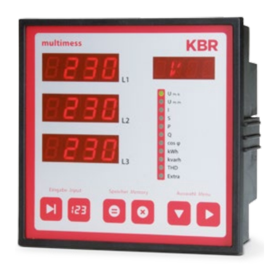
Control and display panel KBR multimess F144-0-LED-...-5 Control and display panel multimess Ph-N Ph-Ph cos φ kvarh Extra Eingabe Input Speicher Memory Auswahl Menu Rev. 5.00... -
Page 22: Description Of Sensor Buttons And Displays
KBR multimess F144-0-LED-...-5 Control and display panel Description of sensor buttons and displays Three 4-digit 7-segment displays are used to display the measured, stored and programmed values (3-phase; L1-L2-L3). Starts the programming mode and switches between the seg- ments to be edited in . -
Page 23: Operation
Navigation and device displays KBR multimess F144-0-LED-...-5 NOTE The display on the measuring device has a dimming function (energy saving function). After a set time has expired (15 minutes), the display brightness is reduced unless the sensor key is pressed (value is not adjustable). If any key is pressed, the original display brightness is restored. -
Page 24: Navigation And Device Displays
KBR multimess F144-0-LED-...-5 Navigation and device displays Navigation and device displays Main menus Submenus U PH-N U PH-N Frequency L1; L2; L3 Frequency correction 4 sec. U PH-PH U PH-PH Phase angle Asymmetry L1; L2; L3 U primary U secondary 4 sec. -
Page 25: Setting The Operating Parameters
Set the operating parameters KBR multimess F144-0-LED-...-5 Setting the operating parameters General programming scheme Press this button for 4 seconds to switch to programming mode from a main menu or submenu. The current parameters are displayed. Press this button again to activate parameter input mode. -
Page 26: U Ph-Ph
KBR multimess F144-0-LED-...-5 Set the operating parameters - measuring reference voltage/rated mains voltage Ph-Ph Menu Button(s) Device display Description Main menu UPh-Ph Sub menu When you open the menu, the fol- Press and 0400 Set voltage lowing text is shown on the display:... -
Page 27: I - Current Transformer Ratio
Setting parameters KBR multimess F144-0-LED-...-5 I - Current transformer ratio Menu Button(s) Device display Description Main menu I Submenu When you open the menu, the fol- Press and 1000 Current lowing text is shown on the display: hold button Set transform-... -
Page 28: I N - Current Transformer Ratio
KBR multimess F144-0-LED-...-5 Setting parameters - Current transformer ratio Menu Button(s) Device display Description Main menu I Submenu When you open this menu, the fol- Press and 0005 current I lowing text is shown on the display: hold button transformer... - Page 29 Setting parameters KBR multimess F144-0-LED-...-5 Menu Button(s) Device display Description Submenu Change Display L3 flashes. Press the 1000 current I value or button to set the number. measurement Ph-N Ph-Ph Cancel Display L3 shows the measurement type type. cos φ...
-
Page 30: Display Functions
KBR multimess F144-0-LED-...-5 Display functions Display functions 10.1 - Voltage phase to neutral conductor, frequency Ph-N Menu Button(s) Device display Description Main menu Displays the three phase voltages and U in the displays Ph-N L1-N L2-N L3-N L1 to L3. -
Page 31: Voltage Phase To Phase, Rotary Field Display
Description of the display window KBR multimess F144-0-LED-...-5 10.2 - Voltage phase to phase, rotary field display Ph-Ph Menu Button(s) Device display Description Main menu The three phase-to-phase voltages and U are shown in Ph-Ph L1-L2 L2-L3 L3-L1 the displays L1 to L3. -
Page 32: I/I - Current/Neutral Conductor Current, Ipe
KBR multimess F144-0-LED-...-5 Description of the display window 10.3 - Current/neutral conductor current, I (PE – leakage calculated), instantaneous- average value switching Menu Button(s) Device display Description Main menu Displays the three conductor cur- I Instanta- rents in phases L1, L2 and L3. - Page 33 Description of the display window KBR multimess F144-0-LED-...-5 Menu Button(s) Device display Description Submenu Display L1 shows the instantaneous Neutral neutral conductor current. conductor Ph-N Ph-Ph The unit display switches between current NACT and A. cos φ kvarh next sub-...
-
Page 34: S - Apparent Power / Total Apparent Power
KBR multimess F144-0-LED-...-5 Description of the display window 10.4 S - Apparent power / total apparent power Menu Button(s) Device display Description Main menu The displays L1 to L3 show the 23.5 S Apparent apparent power of the three power phases. -
Page 35: P - Active Power / Total Active Power
Description of the display window KBR multimess F144-0-LED-...-5 10.5 P - Active power / total active power Menu Button(s) Device display Description Main menu The displays L1 to L3 show the P Active active power of the three phases. power... -
Page 36: Q - Reactive Power / Total Reactive Power
KBR multimess F144-0-LED-...-5 Description of the display window 10.6 Q - Reactive power / total reactive power Menu Button(s) Device display Description Main menu Displays L1 to L3 show the reactive KVAR i114 Q Reactive power of the three phases. -
Page 37: Cos Φ - Fundamental Power Factor, Pf, Total Pf
Description of the display window KBR multimess F144-0-LED-...-5 10.7 Cos φ - Fundamental power factor, PF, total PF Menu Button(s) Device display Description Main menu Display of cosφ. Cos φ Display L1 shows the cosφ for Ph-N phase L1. (i = inductive, c = capac-... -
Page 38: Kwh - Active Energy Ht/Lt Consumption, Maximum Cumulated Active Energy Of The Period
KBR multimess F144-0-LED-...-5 Description of the display window 10.8 kWh – Active energy HT/LT consumption, maximum cumulated active energy of the period Menu Button(s) Device display Description Main menu Active energy meter for high tariff 1234 consumption. Active energy Ph-N... - Page 39 Description of the display window KBR multimess F144-0-LED-...-5 Continued Menu Button(s) Device display Description Submenu When you open the menu, the PCum-Max following text is shown in the unit Maximum cu- display: Ph-N Ph-Ph mulated cycle 12:10 PC.MX MAXIMUM CUMULATED...
-
Page 40: Kvarh - Reactive Energy Meter Ht/Lt Consumption, Maximum Cumulated Cycle Reactive Power
KBR multimess F144-0-LED-...-5 Description of the display window 10.9 kvarh - Reactive energy meter HT/LT consumption, maximum cumulated cycle reactive power Menu Button(s) Device display Description Main menu Reactive energy meter for high 1234 kvarh tariff consumption. Reactive Ph-N Display L3 - L1 shows the value of... - Page 41 Description of the display window KBR multimess F144-0-LED-...-5 Continuation of table 10.9 Menu Button(s) Device display Description Submenu When you open the menu, the following text is shown in the unit Kum-Max Maximum cu- display: Ph-N Ph-Ph mulated cycle 12:10 QC.MX MAXIMUM CUMULATED...
-
Page 42: Thd- Distortion Factor And Partial Harmonic Content Of The Voltage And Current Network Harmonics
KBR multimess F144-0-LED-...-5 Description of the display window 10.10 THD- distortion factor and partial harmonic content of the voltage and current network harmonics Menu Button(s) Device display Description Main menu Display L1 shows the distortion fac- next sub- tor in % for the voltage of phase L1. -
Page 43: Extra
Description of the display window KBR multimess F144-0-LED-...-5 10.11 Extra Menu Button(s) Device display Description Main menu Display L1 shows the device type Extra (here: Comfort). Ph-N Ph-Ph Display L2 shows the version num- 5:00 ber. Display L3 shows the release number. - Page 44 KBR multimess F144-0-LED-...-5 Description of the display window Continuation of table 10.11 Menu Button(s) Device display Description Submenu Display L1 shows the on- REL2 delay for relay 2 in seconds. REL 2 Display L2 shows the off-delay for Ph-N Ph-Ph relay 2 in seconds.
- Page 45 Extra menu Submenu Re- The device is reset to the default set to default DEF. KBR factory settings. All stored values are lost. Ph-N Ph-Ph settings The unit display shows DEFAULT PARAMETER and then DEF. cos φ...
- Page 46 KBR multimess F144-0-LED-...-5 Description of the display window Continuation of table 10.11 Menu Button(s) Device display Description Submenu but- Display L1 shows the status of the TOTAL ton buzzer button buzzer. You can choose from “ON” or “OFF”. Ph-N Ph-Ph The unit display shows SUMMER and then SUMM.
-
Page 47: Maximum / Minimum Extreme Values Display
Description of the display window KBR multimess F144-0-LED-...-5 10.12 Maximum / Minimum extreme values display The following section explains how to display the extreme values. The maxi- mum and minimum values of the phase voltages will be used as an example. - Page 48 KBR multimess F144-0-LED-...-5 Description of the display window NOTE Use the button to switch from maximum to minimum values. The minimum values are read the same way as the maximum values. The following table gives an overview of all extreme values stored in the multimess F144-0-LED-...-5.
- Page 49 Description of the display window KBR multimess F144-0-LED-...-5 Continued Menu Measured value Stored Text dis- extreme values played in de and en Main menu Fundamental Minimum and maximum value of L1 - L2 Min and Max COS φ power factor...
-
Page 50: Displaying Limits
2 Extra Display L3 shows the message type for the limit: OFF: Message only via the KBR- eBus, REL1 additional message at relay 1 REL2 additional message at relay 2 If a limit is violated, the LED of the respective main menu starts to flash. - Page 51 Description of the display window KBR multimess F144-0-LED-...-5 The following table gives an overview of all limits available in the multimess F144-0-LED-...-5. Menu Measured value Programmed Text diplayed limits in de and en Main menu Phase voltage Limit 1 and limit 2 for...
-
Page 52: Programming
KBR multimess F144-0-LED-...-5 Programming Programming 11.1 Period time current average value Menu Button(s) Device display Description Main menu When you open this menu, the Hold the TIME following text button for 4 Submenu Ph-N is shown on the display: seconds. -
Page 53: Tariff Switching Method
Programming KBR multimess F144-0-LED-...-5 11.2 Tariff switching method Menu Button(s) Device display Description Main menu When you open this menu, the fol- Hold the TARF kWh/HT Sub- lowing text is shown on the display: button for 4 menu Tariff Ph-N TARF LT TARIFF TIMES seconds. -
Page 54: Programming Limits
The display L3 shows how the limit Extra violation is communicated. - Alarm on relay 1 (REL1) - Alarm on relay 2 (REL2) - Alarm only via KBR eBus (OFF) Submenu The first digit on the display L1 Change value Voltage Lim1 flashes. - Page 55 - Alarm on relay 1 (REL1) Set message - Alarm on relay 2 (REL2) cos φ Save type - Alarm only via KBR eBus (OFF) rEL1 kvarh Extra Return to main menu. Continue to the next submenu, if available, NOTE or return to the main menu.
-
Page 56: Parameterizing Hysteresis For Programming Limits
KBR multimess F144-0-LED-...-5 Programming 11.3.1 Parameterizing hysteresis for programming limits The following section explains how to parameterize the hysteresis of the limits. Limit 1 of the phase voltage serves as an example. Menu Button(s) Device display Description Submenu Maximum Lim1... - Page 57 Programming KBR multimess F144-0-LED-...-5 Continued Menu Button(s) Device display Description With back to HYST the limit input. Ph-N Ph-Ph cos φ kvarh Extra NOTE Programming the hysteresis for limit 2 is identical. Rev. 5.00...
-
Page 58: Setting Time And Date
KBR multimess F144-0-LED-...-5 Programming 11.4 Setting time and date Menu Button(s) Device display Description Main menu Display L1 shows the time Start 2:32 Extra (hh.mm). Display L2 shows the date input mode (dd.mm). Ph-N Ph-Ph Submenu 10:11 Display L3 shows the year (yyyy). -
Page 59: Setting The Relay On-Delay And Off-Delay
Programming KBR multimess F144-0-LED-...-5 11.5 Setting the relay on-delay and off-delay Menu Button(s) Device display Description Submenu Display L1 shows the on-delay for Start input REL1 REL 1 relay 1 in seconds. Display L2 shows mode the off-delay for relay 1 in seconds. - Page 60 L1 ----, L2 ---- Extra and L3 BUS. Save Configuration is only possible via KBR eBus using optionally available software. Return to main menu Continue to the next submenu, if available, or Return to main menu.
-
Page 61: Activating Daylight Saving Time
Programming KBR multimess F144-0-LED-...-5 11.6 Activating daylight saving time Menu Button(s) Device display Description Submenu Display L1 indicates whether daylight Start input Daylight sav- saving time is activated or not. mode ing time Ph-N Display L2: shows the month daylight Ph-Ph saving time begins. -
Page 62: Language Settings
KBR multimess F144-0-LED-...-5 Programming Continued Menu Button(s) Device display Description Submenu Display L3 flashes. Change value Daylight sav- Press the button to set the ing time Ph-N month daylight saving time ends. Ph-Ph Cancel on/off The unit display switched between END and DST. -
Page 63: Password
Programming KBR multimess F144-0-LED-...-5 11.8 Password Menu Button(s) Device display Description Submenu Display L1 shows CODE. Start input COdE LOCK Password The unit display mode Ph-N shows LOCK or FREE. Ph-Ph ---- L2 shows ---- The device is defaulted with the cos φ... -
Page 64: Configuring The Pulse Output
KBR multimess F144-0-LED-...-5 Programming 11.9 Configuring the pulse output Menu Button(s) Device display Description Submenu Display L1 indicates , whether the pulse Start input PULSE Pulse output is deactivated (OFF) or config- mode output ured for active (P) or reactive (Q) energy. - Page 65 Programming KBR multimess F144-0-LED-...-5 Continued Menu Button(s) Device display Description Submenu When you open the menu, the Change value Pulse following text is displayed in the LEN. output unit display: Ph-N Next digit LEN. LENGTH LEN Ph-Ph Set pulse 2,000 The first digit in display L3 flashes.
-
Page 66: Damping Coefficient
KBR multimess F144-0-LED-...-5 Programming 11.10 Damping coefficient Menu Button(s) Device display Description Submenu Display L1 shows the damping coeffi- Start input Damp. cient for acquiring the voltage. mode Factor DF Display L2 shows the damping coeffi- Ph-N Ph-Ph cient for acquiring the current. -
Page 67: Default Settings
Programming KBR multimess F144-0-LED-...-5 11.11 Default settings Menu Button(s) Device display Description Submenu The unit display shows DEF. DEF. Default settings Ph-N Ph-Ph cos φ kvarh Extra Submenu When you press these three Press Default KILL buttons at the same time, the... -
Page 68: Zero Point Creator
KBR multimess F144-0-LED-...-5 Programming 11.12 Zero point creator Menu Button(s) Device display Description Submenu Display L1 shows the state of the Start input Zero point zero point creator. mode creator Ph-N Ph-Ph cos φ kvarh Extra Submenu When you open the menu: Display... -
Page 69: Key Sounds (Button Buzzer)
Programming KBR multimess F144-0-LED-...-5 11.13 Key sounds (button buzzer) Menu Button(s) Device display Description Submenu Display L1 shows the state of the Start input TOTAL button buzzer button buzzer. mode Ph-N Ph-Ph cos φ kvarh Extra Activate / When you open the menu:... -
Page 70: Default Menu (Start Selection)
KBR multimess F144-0-LED-...-5 Programming 11.14 Default menu (start selection) Menu Button(s) Device display Description Submenu Display L1 shows the selected Start input MENU Default menu default menu (02 = U mode PH-PH (start selec- Ph-N Ph-Ph Display L2 shows the return time in tion) seconds in the default menu. -
Page 71: Reset And Delete Function
Reset and delete function KBR multimess F144-0-LED-...-5 Reset and delete function 12.1 Reset To reset, go to the Default settings submenu of the Extra menu. Only reset the energy Hold the buttons digit, delete and right arrow at the same meter during setup or if time. -
Page 72: Deleting All Extreme Values
KBR multimess F144-0-LED-...-5 Reset and delete function 12.3.2 Deleting all extreme values To delete all minimum and maximum values, hold the buttons about 4 seconds while any minimum or maximum value is displayed. 12.4 Deleting limit settings 12.4.1 Deleting individual limit settings You can only deactivate individual limits in programming mode. -
Page 73: Memory Functions
Memory functions KBR multimess F144-0-LED-...-5 Memory functions 13.1 Device settings All device settings and configuration data for the memory function are stored in the device. 13.2 Basic device parameters Parameter Stored by user Measuring voltage can be programmed by user in the range from 0001 V to 999.9 kV... -
Page 74: Technical Data
KBR multimess F144-0-LED-...-5 Technical data Technical data 14.1 Measuring and display values Wave form for U and I Voltage RMS value Phase - N: U L1-N L2-N L3-N of a measuring interval phase - phase: U L1-2 L2-3 L3-1 Units [V, kV];... - Page 75 Technical data KBR multimess F144-0-LED-...-5 Continued Reactive Calculation ind. total power & cap. distinction between ind./cap. Units [var; kvar; Mvar]; display switches automatically. Measuring period 0.00VAr to 999Mvar memory Active Calculation W(HT/LT) energy Units [Wh; kWh; MWh; GWh]; display switches automatically Measuring period 0.0 Wh to 9999 GWh...
-
Page 76: Measurement Accuracy Class (In Accordance With Din En 61557-12)
KBR multimess F144-0-LED-...-5 Technical data 14.2 Measurement accuracy class (in accordance with DIN EN 61557-12) Measured value Symbol Accuracy class Voltage 0.2 / ± 1 digit Voltage 0.2 / ± 1 digit PHPH Phase current 0.5 / ± 1 digit Neutral conductor current measured 0.5 / ±... -
Page 77: Device Memory
Technical data KBR multimess F144-0-LED-...-5 14.4 Device memory Energy, data and parameter memory 2 MB Flash Program memory 512 kB flash Memory type Ring buffer Long-term memory (1 year) Daily values for active and reactive energy (HT and LT) for consumption and recovery... -
Page 78: Hardware Inputs And Outputs
KBR multimess F144-0-LED-...-5 Technical data 14.6 Hardware inputs and outputs 14.6.1 Inputs Voltage 3 x 5 V - 100 V - 120 V AC (measuring range L1-L2 L2-L3 L3-L1 measuring inputs 3 x 20 V - 500 V - 600 V AC (measuring range Input impedance 1.2 MOHM (Ph-Ph) -
Page 79: Electrical Connection
Technical data KBR multimess F144-0-LED-...-5 14.7 Electrical connection Connection elements Plug-in terminals Permissible cross-section 2.5 mm of the connecting cables Measurement Fuse protection max. 1 A slow-blow max. C2 automatic voltage inputs isolating switch UL/IEC-approved Measurement Fuse protection NONE!!! Always short-circuit current trans-... -
Page 80: Ambient Conditions, Electrical Safety And Standards
KBR multimess F144-0-LED-...-5 Technical data 14.9 Ambient conditions, electrical safety and standards Ambient Standards DIN EN 60721-3-3:1995-09 + conditions DIN EN 60721-3-3/A2:1997-07; 3K5+3Z11; (IEC721-3-3;3K5+3Z11) Operating tem- K55 (-5 °C - +55 °C) perature Humidity 5% - 95% non-condensing Storage tem- K55 (-25°C ... -
Page 81: Overvoltage And Lightning Protection
Overvoltage protection / Troubleshooting KBR multimess F144-0-LED-...-5 Overvoltage and lightning protection To protect your purchased high-quality devices from damage, we strongly recommend that you take overvoltage protection measures. Protect control voltage inputs, pulse and bus lines. Troubleshooting No function. Check the power supply, back-up fuse, isolating switch and supply line. - Page 82 KBR multimess F144-0-LED-...-5 Notes Rev. 5.00...
- Page 83 Notes KBR multimess F144-0-LED-...-5 Rev. 5.00...
- Page 84 KBR Kompensationsanlagenbau GmbH www.kbr.de Am Kiefernschlag 7 T +49 (0) 9122 6373 - 0 D-91126 Schwabach F +49 (0) 9122 6373 - 83 Germany E- info@ kbr.de...
Need help?
Do you have a question about the multimess F144-0-LED 5 Series and is the answer not in the manual?
Questions and answers