
Subscribe to Our Youtube Channel
Related Manuals for KBR F144-2-LED-ESMS 5 Series


Summary of Contents for KBR F144-2-LED-ESMS 5 Series
- Page 1 User manual Technical parameters Three-phase network measuring device F144-2-LED-ESMS...-5 multimess Your partner for network analysis System English...
-
Page 2: Table Of Contents
Programming limits ......52 I /IN - Current / neutral conductor Setting time and date ..... 54 current, instantaneous and average value switch-over .... 29 Setting the bus address ....55 © KBR Kompensationsanlagenbau GmbH Misprints, printing errors and technical changes reserved... - Page 3 Synchronization by the energy and setting the relay off-delay ..60 supplier’s synchronous pulse..77 9.11 Language settings ......61 11.10 Synchronization by KBR eBus ..77 9.12 Password ..........62 11.11 Synchronization at tariff change 78 9.13 Configuring the pulse output ..63 Technical data ........
- Page 4 Introduction Dear customer Thank you for choosing a KBR product. To familiarize yourself with operation and configuration of the device, we recommend that you read this manual carefully. This will enable you to make use of the entire range of functions that this high-quality product offers.
- Page 5 Introduction KBR multimess F144-2-LED-ESMS...-5 This manual contains notes that must be observed for your personal safety and to avoid damage to the equipment. These notes are identified by a warning sign or information symbol, depending on the degree of hazard they warn about.
- Page 6 KBR multimess F144-2-LED-ESMS...-5 Introduction DANGEROUS VOLTAGE The applicable DIN/VDE regulations must be observed for installation! Power supply connection, setup and operation of the device may only be performed by qualified personnel. Qualified personnel as defined in the safety notes in this user manual are personnel with electrical engineering qualifica-...
- Page 7 Introduction KBR multimess F144-2-LED-ESMS...-5 Product liability You have purchased a high-quality product. Only components of the highest quality and maximum reliability are used. Each device is subject to long-term testing before it is delivered. For details on product liability, please refer to our general terms and conditions for electronic equipment.
-
Page 8: Device Memory, Battery-Buffered
KBR multimess F144-2-LED-ESMS...-5 Device memory Device memory, battery-buffered NOTE Before the initial start-up of the device, please insert the backup battery first (as described in the following), as otherwise any data stored would be lost in the event of power failure. - Page 9 Device memory KBR multimess F144-2-LED-ESMS...-5 Contact spring Battery holder Battery Front cover Device frame...
-
Page 10: Definition Of Terms
KBR multimess F144-2-LED-ESMS...-5 Definition of terms Definition of terms Below, you will find a brief explanation of the terminology used in this manual. Root mean square value: By definition, the square mean value of a periodic or pulsating quantity is referred to as the RMS value. -
Page 11: Field Of Application / Range Of Functions
Switching from high to low tariff times and vice versa is either carried out by means of a digital signal to be applied externally, e.g. from the energy supplier, or via an internal clock. When operated with the KBR Energy Bus, switching can be done centrally via the ve-busmaster. - Page 12 such as power failures, tariff switching actions, delete functions and many more. These memory functions are exclusively available via the KBR Energy Bus. Synchronization To synchronize the load profile memory, a separate digital input was integrated into the multimess F144-2-LED-ESMS-...-5 where you can, for example, connect the synchronization signal of the energy supplier’s meter.
-
Page 13: Connecting The Multimess F144-2-Led-Esms
Installation and electrical connection KBR multimess F144-2-LED-ESMS...-5 term data. Separate power supply The device requires a separate auxiliary voltage for operation. (see nameplate) If you have any questions on this device or our software products, please don’t hesitate to contact us. It is our pleasure to assist you. - Page 14 KBR multimess F144-2-LED-ESMS...-5 Installation and electrical connection CAUTION The control voltage as well as the applied measuring voltage of the device must be protected by means of a back-up fuse. When connecting the current transformers, pay attention to the energy flow...
- Page 15 Installation and electrical connection KBR multimess F144-2-LED-ESMS...-5 For the wiring of the pulse output, we recommend to exclusively use shielded twisted pair material to avoid disturbances (e.g. installation line I-Y(ST) Y 2 x 2 x 0.8 mm. The shielding may only be connected on one side).
- Page 16 KBR multimess F144-2-LED-ESMS...-5 Installation and electrical connection Current transformer connection: Energy flow direction: When installing the transformers, observe the current flow / energy flow direc- tion. If the current transformer is installed the wrong way, the measured value will be negative.
-
Page 17: Connection Diagram
Installation and electrical connection KBR multimess F144-2-LED-ESMS...-5 Connection diagram... -
Page 18: Terminal Assignment
KBR multimess F144-2-LED-ESMS...-5 Installation and electrical connection Terminal assignment Terminal 1 (L) and 2 (N): Power supply connection A control voltage is required to supply the device with power. The device has a multi-range power supply unit and can be sup- plied with different voltages (see nameplate). - Page 19 Installation and electrical connection KBR multimess F144-2-LED-ESMS...-5 Terminal 36 and 37: Synchronization input A floating contact, e.g. from the energy supplier, can be connect- ed to this input to synchronize the measurement period 38 (-) and 39 (+): Tariff input A floating contact, e.g.
-
Page 20: Control And Display Panel
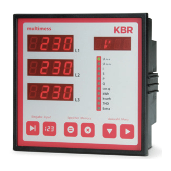
KBR multimess F144-2-LED-ESMS...-5 Control and display panel Control and display panel multimess Ph-N Ph-Ph cos φ kvarh Extra Eingabe Input Speicher Memory Auswahl Menu... -
Page 21: Description Of Sensor Buttons And Displays
Control and display panel KBR multimess F144-2-LED-ESMS...-5 Description of sensor buttons and displays Three 4-digit 7-segment displays to show measured, stored and programmed values (3-phase; L1-L2-L3). 2 Starts the programming mode and switches between the seg- ments to be edited in . -
Page 22: Operation
KBR multimess F144-2-LED-ESMS...-5 Navigation and device displays Operation Menu structure of the multimess F144-2-LED-ESMS-...-5 Switches between the main menus. When you are in a menu, the corresponding LED lights up (not flashing). Hold the button to automatically switch between the individual main menus. -
Page 23: Navigation And Device Displays
Navigation and device displays KBR multimess F144-2-LED-ESMS...-5 Navigation and device displays Main menus Submenus U PH-N U PH-N Frequency L1; L2; L3 Frequency 2 sec. correction U PH-PH U PH-PH Phase angle Asymmetry L1; L2; L3 U primary U ... -
Page 24: Setting Operating Parameters
KBR multimess F144-2-LED-ESMS...-5 Setting parameters Setting operating parameters General programming scheme Press this button for 2 seconds to switch into the programming mode from a main menu or submenu. The set parameters are displayed. Press this button again to activate the parameter input mode. -
Page 25: U Ph-Ph - Measuring Reference Voltage / Rated Mains Voltage
Setting parameters KBR multimess F144-2-LED-ESMS...-5 U Ph-Ph - Measuring reference voltage / rated mains voltage Menu Button(s) Device display Description Main menu UPh-Ph Submenu When you open the menu, the Hold the 0400 Voltage following text is shown in the unit... -
Page 26: I - Current Transformer Ratio
KBR multimess F144-2-LED-ESMS...-5 Setting parameters I - Current transformer ratio Menu Button(s) Device display Description Main menu Submenu When you open the menu, the Hold the 1000 Current Set following text is shown in the unit button for 2... -
Page 27: Display Functions
Display functions KBR multimess F144-2-LED-ESMS...-5 Display functions UPh-N - Voltage phase to neutral conductor, frequency Menu Button(s) Device display Description Main menu Displays the three phase voltages and U in the displays Ph-N L1-N L2-N L3-N L1 to L3. Ph-PN... -
Page 28: Uph-Ph - Voltage Phase To Phase, Rotary Field Display
KBR multimess F144-2-LED-ESMS...-5 Description of the display window UPh-Ph - Voltage phase to phase, rotary field display Menu Button(s) Device display Description Main menu The three phase-to-phase voltages and U are shown in Ph-Ph L1-L2 L2-L3 L3-L1 the displays L1 to L3. -
Page 29: I /In - Current / Neutral Conductor Current, Instantaneous And Average Value Switch-Over
Description of the display window KBR multimess F144-2-LED-ESMS...-5 I /IN - Current / neutral conductor current, instantaneous and average value switch-over Menu Button(s) Device display Description Main menu Displays the three conductor cur- I Instanta- rents in the phases L1, L2 and L3. -
Page 30: S - Apparent Power / Total Apparent Power
KBR multimess F144-2-LED-ESMS...-5 Description of the display window Menu Button(s) Device display Description Submenu Display L1 shows the instantaneous 5. 0 Neutral neutral conductor current. conductor Ph-PN The unit display switches between Ph-Ph current NACT and A. cos φ kvarh Harmon. -
Page 31: P - Active Power / Total Active Power
Description of the display window KBR multimess F144-2-LED-ESMS...-5 P - Active power / total active power Menu Button(s) Device display Description Main menu The displays L1 to L3 show the ac- P Active tive power of the three phases. -
Page 32: Q - Reactive Power / Total Reactive Power
KBR multimess F144-2-LED-ESMS...-5 Description of the display window Q - Reactive power / total reactive power Menu Button(s) Device display Description Main menu Displays L1 to L3 show the reactive %114 KVAR Q Reactive power of the three phases. -
Page 33: Cos Φ - Fundamental Power Factor, Pf, Total Pf
Description of the display window KBR multimess F144-2-LED-ESMS...-5 Cos φ - Fundamental power factor, PF, total PF Menu Button(s) Device display Description Main menu Display of cosφ. Cos φ Display L1 shows the cosφ for Ph-PN phase L1. (i = inductive, c = capaci-... -
Page 34: Kwh - Active Energy Ht/Lt Consumption And Recovery, Maximum Cumulated Cycle Active Power
KBR multimess F144-2-LED-ESMS...-5 Description of the display window kWh - Active energy HT/LT consumption and recovery, maximum cumulated cycle active power Menu Button(s) Device display Description Main menu Active energy meter for high tariff 1234 consumption. Display L3 - L1 shows... - Page 35 Description of the display window KBR multimess F144-2-LED-ESMS...-5 Continued Submenu kWh Active energy meter for low tariff next or Active energy 1234 recovery. Low tariff Re- Ph-PN Display L3 - L1 shows the value of Ph-Ph covery the continuous energy meter.
-
Page 36: Kvarh - Reactive Energy Meter Ht/Lt Consumption And Recovery, Maximum Cumulated Cycle Reactive Power
KBR multimess F144-2-LED-ESMS...-5 Description of the display window kvarh - Reactive energy meter HT/LT consumption and recovery, maximum cumulated cycle reactive power Menu Button(s) Device display Description Main menu Reactive energy meter for high 1234 kvarh tariff consumption. Display L3 - L1... - Page 37 (dd.mm.yyyy). Main menu kvarh NOTE The daily energy meters (for active and reactive energy) of the device can only be read out via the KBR Energy Bus with the optionally available software.
-
Page 38: Harmon. - Distortion Factor And Partial Harmonic Content Of The Voltage And Current Network Harmonics
KBR multimess F144-2-LED-ESMS...-5 Description of the display window 8.10 Harmon. - distortion factor and partial harmonic content of the voltage and current network harmonics Menu Button(s) Device display Description Main menu Display L1 shows the distortion fac- next or 4. -
Page 39: Extra
Description of the display window KBR multimess F144-2-LED-ESMS...-5 8.11 Extra Menu Button(s) Device display Description Main menu Display L1 shows the device type Extra (here: Basic). Ph-PN Ph-Ph Display L2 shows the version num- ber. Display L3 shows the release number. - Page 40 KBR multimess F144-2-LED-ESMS...-5 Description of the display window Continued Menu Button(s) Device display Description Submenu Display L1 shows the on-delay for REL2 REL 2 relay 2 in seconds. next or Display L2 shows the off-delay for Ph-PN Ph-Ph relay 2 in seconds.
- Page 41 Extra Harmon. Extra Submenu The device is reset to the default Reset to DEF. KBR factory settings. All stored next or default values are lost. Ph-PN Ph-Ph settings The unit display shows DEFAULT PARAMETER and then DEF.
- Page 42 KBR multimess F144-2-LED-ESMS...-5 Description of the display window Continuation of table 8.11 Menu Button(s) Device display Description Submenu Display L1 and the unit display 4-20 Analog inter- show the output type. You can faces next or choose from: Ph-PN...
-
Page 43: Maximum / Minimum Extreme Values Display
Description of the display window KBR multimess F144-2-LED-ESMS...-5 8.12 Maximum / Minimum extreme values display The following section explains how to display the extreme values. The maxi- mum and minimum values of the phase voltages will be used as an example. - Page 44 KBR multimess F144-2-LED-ESMS...-5 Description of the display window NOTE Use the button to switch from maximum to minimum values. The minimum values are read the same way as the maximum values. The following table gives an overview of all extreme values stored in the multimess F144-2-LED-ESMS-...-5.
- Page 45 Description of the display window KBR multimess F144-2-LED-ESMS...-5 Continued Menu Measured value Stored Text dis- extreme values played in de and en Submenu Power factor Minimum and maximum value of the Min and Max Total PF total power factor total with date and time...
-
Page 46: Displaying Limits
Harmon. Display L3 shows the message type Extra for the limit: OFF message only via KBR Energy Bus: rEL1 additional message at relay 1 rEL2 additional message at relay 2 If a limit is violated, the LED of the respective main menu starts to ... - Page 47 Description of the display window KBR multimess F144-2-LED-ESMS...-5 NOTE If a relay is not configured as alarm relay but as a switching relay (setting only possible via eBus), L3 does not display anything. The following table gives an overview of all limits available in the multimess F144-2-LED-ESMS-...
- Page 48 KBR multimess F144-2-LED-ESMS...-5 Description of the display window Continued Menu Measured value Programmed Text dis- limits played in de and en Submenu Power factor Limit 1 and limit 2 for GW 1 and GW 2 Power factor L1 - L2 - L3...
-
Page 49: Programming
Programming KBR multimess F144-2-LED-ESMS...-5 Programming Period time current average value Menu Button(s) Device display Description Main menu When you open the menu, the Hold the TIME following text is shown in the unit button for 2 Submenu display: Ph-PN seconds. -
Page 50: Tariff Switching Method
KBR multimess F144-2-LED-ESMS...-5 Programming Tariff switching method Menu Button(s) Device display Description Main menu When you open the menu, the Hold the d. I n TARF Main menu following text is shown in the unit button for 2 kWh/HT Sub-... -
Page 51: Measurement Period Synchronization
Programming KBR multimess F144-2-LED-ESMS...-5 Measurement period synchronization Menu Button(s) Device display Description Submenu When you open the menu, the Hold the d. I n SYNC kWh/LT following text is shown in the unit button for 2 Submenu display: Ph-PN... -
Page 52: Programming Limits
KBR multimess F144-2-LED-ESMS...-5 Programming Programming limits The following section explains how to parameterize the limits. The limits 1 and 2 of the phase voltage serve as an example. Menu Button(s) Device display Description Submenu Display L1 shows the limit value. - Page 53 - Alarm on relay 2 (rel2) kvarh rELI Harmon. save - Alarm only via KBR Energy Bus (OFF) Extra Main menu Ph-N NOTE If a relay is not configured as alarm relay but as a switching relay (setting only...
-
Page 54: Setting Time And Date
KBR multimess F144-2-LED-ESMS...-5 Programming Setting time and date Menu Button(s) Device display Description Main menu Display L1 shows the time (hh.mm). 14: 3 2 Extra Display L2 shows the date (dd.mm). Display L3 shows the year (yyyy). Ph-PN Ph-Ph Submenu The unit display shows the week- 10. -
Page 55: Setting The Bus Address
Programming KBR multimess F144-2-LED-ESMS...-5 Setting the bus address Menu Button(s) Device display Description Main menu Display L1 shows the device address. 0001 EBUS Extra The baud rate is displayed in dis- play L2. Ph-PN Ph-Ph Submenu 38. 4 Start input eBus cos φ... -
Page 56: Setting The Bus Protocol
KBR multimess F144-2-LED-ESMS...-5 Programming Setting the bus protocol Menu Button(s) Device display Description Submenu Display L1 shows the device address. 0001 EBUS eBus The baud rate is displayed in display Ph-PN Ph-Ph The unit display shows the current 38. 4 ... -
Page 57: Setting The Modbus Bus Address And Baud Rate
Programming KBR multimess F144-2-LED-ESMS...-5 Setting the Modbus bus address and baud rate Menu Button(s) Device display Description Submenu Display L1 shows the device address. 0001 MBUS Modbus The baud rate is displayed in display L2. Display L3 shows the selected bus... -
Page 58: Setting The Relay On-Delay And Off-Delay
KBR multimess F144-2-LED-ESMS...-5 Programming Setting the relay on-delay and off-delay Menu Button(s) Device display Description Submenu Display L1 shows the on-delay for REL1 REL 1 relay 1 in seconds. Display L2 shows the off-delay for relay 1 in seconds. Ph-PN... - Page 59 Programming KBR multimess F144-2-LED-ESMS...-5 NOTE Relay 2 is set the same way as relay 1.
-
Page 60: Activating Daylight Saving Time And Setting The Relay Off-Delay
KBR multimess F144-2-LED-ESMS...-5 Programming 9.10 Activating daylight saving time and setting the relay off-delay Menu Button(s) Device display Description Submenu Display L1 indicates whether daylight Daylight sav- saving time is activated or not. ing time Ph-PN Display L2 shows the month daylight Ph-Ph saving time begins. -
Page 61: Language Settings
Programming KBR multimess F144-2-LED-ESMS...-5 Continued Menu Button(s) Device display Description Submenu Display L3 flashes. ..Daylight sav- Press the V button to set the month next digit ing time Ph-PN daylight saving time ends. Ph-Ph on/off The unit display switched between ... -
Page 62: Password
KBR multimess F144-2-LED-ESMS...-5 Programming 9.12 Password Menu Button(s) Device display Description Submenu Display L1 shows CODE. code LocK Password The unit display shows LOCK or Ph-PN FREE. Ph-Ph ---- If the device is unlocked, the code num- ber will be displayed in L2. If the device cos φ... -
Page 63: Configuring The Pulse Output
Programming KBR multimess F144-2-LED-ESMS...-5 9.13 Configuring the pulse output Menu Button(s) Device display Description Submenu Display L1 indicates whether the pulse PULS . Pulse output is deactivated (OFF) or config- output ured for active (P) or reactive (q) energy Ph-PN... - Page 64 KBR multimess F144-2-LED-ESMS...-5 Programming Continued Menu Button(s) Device display Description Main menu Extra Use these buttons to switch between the individual displays in input mode (one flashing digit). NOTE Submenu When you open the menu, the fol- ...
-
Page 65: Damping Coefficient
Programming KBR multimess F144-2-LED-ESMS...-5 9.14 Damping coefficient Menu Button(s) Device display Description Submenu Display L1 shows the damping coef- Damp. coef- ficient used to record the voltage. ficient Display L2 shows the damping coef- Ph-PN Ph-Ph ficient to calculate the current. -
Page 66: Default Settings
KBR multimess F144-2-LED-ESMS...-5 Programming 9.15 Default settings Menu Button(s) Device display Description Submenu The unit display shows DEF. DEF. Default settings Ph-PN Ph-Ph cos φ kvarh Harmon. Extra Submenu When you press these three but- Default set- KILL tons at the same time, the follow-... -
Page 67: Zero Point Creator
Programming KBR multimess F144-2-LED-ESMS...-5 9.16 Zero point creator Menu Button(s) Device display Description Submenu Display L1 shows the state of the zero Zero point point creator. creator Ph-PN Ph-Ph Start input cos φ mode kvarh Harmon. Extra Submenu When you open the menu: Display Zero point L1 flashes. -
Page 68: Analog Outputs
KBR multimess F144-2-LED-ESMS...-5 Programming 9.17 Analog outputs Menu Button(s) Device display Description Submenu Display L1 shows the output value of the 4-20 Analog analog outputs 1 to 3. outputs Ph-PN Ph-Ph Start input cos φ mode kvarh Harmon. Extra... - Page 69 Programming KBR multimess F144-2-LED-ESMS...-5 The following output data points are available: Off (output deactivated) Voltage U PH-N L1 Reactive power L1 Voltage U PH-N L2 Reactive power L2 Voltage U PH-N L3 Reactive power L3 Voltage U PH-PH L12 CosPhi L1...
- Page 70 KBR multimess F144-2-LED-ESMS...-5 Programming Menu Button(s) Device display Description Submenu Display L1 AnAI U L1 Analog shows the analog output 1. outputs Ph-PN Display L2 Ph-Ph shows the lower limit and flashes ( 0 . 00 0. 0 0 Display L3 cos φ...
- Page 71 Programming KBR multimess F144-2-LED-ESMS...-5 Continued Menu Button(s) Device display Description Main menu Extra or next sub- menu next submenu Submenu ..Analog out- next digit AnA2 puts When you open the menu, OFF Activate Ph-PN flashes in the unit display.
-
Page 72: Reset And Delete Function
(active or reactive energy, HT or LT, consumption or recovery). 10.2.2 Delete all energy meters To delete all energy meters, you can either reset the device or use the optionally available software and KBR Energy Bus. 10.3 Deleting extreme values 10.3.1 Deleting individual extreme values ... -
Page 73: 10.3.2 Deleting All Extreme Values
In programming mode, set the type of the limit you want to deactivate to "OFF". 10.4.2 Deleting all limit settings To delete all limits, hold the buttons for about 2 seconds while any limit is displayed. The function is also available via the KBR Energy Bus. -
Page 74: Memory Functions
KBR multimess F144-2-LED-ESMS...-5 Memory functions Memory functions 11.1 Device settings All device settings and configuration data for the memory function are stored in the device. 11.2 Basic device parameters Parameter Stored by user Measuring voltage can be programmed by user in the range from 0001 V to 999.9 kV... -
Page 75: Long-Term Memory
Memory functions KBR multimess F144-2-LED-ESMS...-5 11.3 Long-term memory The multimess F144-2-LED-ESMS-...-5 supports the long-term memory func- tionality described in the following section. 11.4 Load profile memory The measuring device has a load profile memory that can record a maximum of up to 35136 entries depending on the number of parameters to be stored... -
Page 76: Event Memory
KBR multimess F144-2-LED-ESMS...-5 Memory functions 11.6 Event memory The event memory saves 4096 events with date, time and status in a ring buffer. The following events are acquired: Event Recording Tariff input Switchover signal HT => LT with date and time Switchover signal LT =>... -
Page 77: Synchronization By The Energy Supplier's Synchronous Pulse
Synchronization by KBR eBus Synchronization is carried out via a telex created either by the computer or the bus master and sent to the selected recipients via the KBR ENERGY BUS . Under certain operating conditions, a subsequent synchronization may be carried out while a measurement period is still running. -
Page 78: Synchronization At Tariff Change
KBR multimess F144-2-LED-ESMS...-5 Memory functions Example: The period time is set to 15 min i.e. 20 kW input power results in a period value of 20 kW (15 min period) If a subsequent synchronization is performed 3 minutes after the period starts and this 3-minute period is saved, the period value recorded is 4 kW. -
Page 79: Technical Data
Technical data KBR multimess F144-2-LED-ESMS...-5 Technical data 12.1 Measuring and display values Wave form for U and I Voltage RMS value of Phase - 0: U L1-N L2-N L3-N a measuring phase - phase: U L1-2 L2-3 L3-1 interval Units [V, kV] display is switched automatically Measuring range 0.00kV to 999.9kV... -
Page 80: 12.2 Measurement Accuracy
KBR multimess F144-2-LED-ESMS...-5 Technical data Continued Active Calculation W (HT/LT); P average max. of a measurement period energy Units [Wh; kWh; MWh]; display is switched automatically Measuring range 0.0kWh to 9999999999.9kWh Reactive Calculation (HT/LT) p ind. or cap. Q React average max. -
Page 81: Measuring Principle
Technical data KBR multimess F144-2-LED-ESMS...-5 12.3 Measuring principle Sampling 128 readings per period A/D converter 10 bit Measurement of U and I Simultaneous recording of U and I read- ings; Update speed ~ 330 ms (complete measuring cycle) Harmonics calculation... -
Page 82: Hardware Inputs And Outputs
KBR multimess F144-2-LED-ESMS...-5 Technical data 12.6 Hardware inputs and outputs 12.6.1 Inputs Voltage 3 x 5 V...100 V...120 V AC (measuring range 1) L1-L2 L2-L3 L3-L1 measurement 3 x 20 V...500 V...600 V AC (measuring range 2) inputs Input impedance 1.2 MOHM (Ph-Ph) Measuring range can be configured using... -
Page 83: Electrical Connection
Max. 10 V at voltage output (min. resistance 1000 ohms) Signal Can be set to 0-10V, 2-10V or 0-20mA, 4-20 Serial inter- RS485 for connection to the KBR eBus or face Modbus; max. 32 devices, up to 1000 de- vices with bus repeater Baud rate... -
Page 84: 12.8 Mechanical Data
KBR multimess F144-2-LED-ESMS...-5 Continued Transformer Connections See wiring diagram connection Analog out- Connections Ensure correct polarity! Interface con- RS485 BUS connector Terminal 90 ( ) nection pins Terminal 91 (A) Pin A Terminal 92 (B) Pin B 12.8 Mechanical data... -
Page 85: Ambient Conditions, Electrical Safety And Standards
Standards DIN EN 61000-6-2:2006-03 + amendment 1:2011-03 DIN EN 61000-6-3:2011-09 + amendment 1:2012-11 DIN EN 61326-1:2013-07 Synchroniza- Type internal, manual, tariff switching or by KBR eBus tion Synchroniza- Adjustable manually once per measurement period if internal tion time synchronization is selected on the device. -
Page 86: 12.10 Default Settings After Reset
KBR multimess F144-2-LED-ESMS...-5 12.10 Default settings after reset Primary voltage / secondary voltage 400 V Primary current / Secondary current Measurement period time 15Min. Measurement period Daylight saving time from months 03 to 10 Low tariff time Switching activated via hardware input on... -
Page 87: Serial Interface
KBR multimess F144-2-LED-ESMS...-5 Serial interface 13.1 RS 485 bus operation The RS485 port of the multimess F144-2-LED-ESMS-...-5 is designed for operation at the eBus. With the eBus, you can operate one or several multimess F144-2-LED-ESMS-...-5 devices across great distances. The bus is connected to the computer via the RS 485 inter- face converter. -
Page 88: Troubleshooting
KBR multimess F144-2-LED-ESMS...-5 Troubleshooting No function. Check the power supply, back-up fuse, isolating switch and supply line. The measuring voltage of a phase is 0V. Check the back-up fuse and isolating switch of the phase. A phase of the current display has a different sign. - Page 89 KBR multimess F144-2-LED-ESMS...-5 ErrU OVERLOAD or ErrI OVERLOAD. ErrU: Voltage input of the measuring amplifier overloaded Switch off measuring voltage and check set transformer ratio. In case of direct measurement, the programmed secondary voltage value must correspond to the mains voltage.
-
Page 90: Appendix
KBR multimess F144-2-LED-ESMS...-5 Appendix 16.1 Added functionality: Profibus The multimess F144-1-LED-ESMS-...-5 is now also available with the Profibus option (new name multimess F144-1-LED-ESMSDP-...-5). The additional functions are described in this appendix (Configuring Profibus) 16.2 Setting the bus protocol Menu Button(s) -
Page 91: Set Profibus Bus Adress
KBR multimess F144-2-LED-ESMS...-5 16.3 Set Profi bus bus address Menu Button(s) Device display Description Main menu Extra Submenu Display L1 shows the device address. 0001 PBUS Profi bus Ph-PN Ph-Ph Start input mode cos φ kvarh Harmon. Extra Submenu The first digit in display L1 is fl ... - Page 92 KBR multimess F144-2-LED-ESMS...-5...
- Page 93 Notes KBR multimess F144-2-LED-ESMS...-5...
- Page 94 KBR multimess F144-2-LED-ESMS...-5 Notes...
- Page 95 Notes KBR multimess F144-2-LED-ESMS...-5...
- Page 96 KBR Kompensationsanlagenbau GmbH www.kbr.de Am Kiefernschlag 7 P +49 (0) 9122 6373 - 0 D-91126 Schwabach, F +49 (0) 9122 6373 - 83 Germany E info@ kbr.de...
Need help?
Do you have a question about the F144-2-LED-ESMS 5 Series and is the answer not in the manual?
Questions and answers