
Subscribe to Our Youtube Channel
Related Manuals for KBR multimess F144-PQ


Summary of Contents for KBR multimess F144-PQ
- Page 1 Bedienungsanleitung Power Quality Netzanalysator multimess F144-PQ In unserem Downloadcenter finden Sie System deutsch zu KBR Geräten die passende Anleitung. https://www.kbr.de/download/ bedienungsanleitungen/...
- Page 2 KBR GmbH does not accept any liability for damage or losses of any kind arising from printing errors or changes in this manual. Furthermore, KBR GmbH will not accept any liability for loss or damage of any kind resul- ting from faulty equipment or devices that have been modified by the user.
-
Page 3: Table Of Contents
Keeping ............................. 7 Scope of Delivery/Order Codes ....................8 Safety instructions ........................10 Meaning of the symbols used on the device ..............10 Site information and assembly instructions of multimess F144-PQ ......11 Intended use ..........................11 Technical Data ..........................12 multimess F144-PQ Description ....................12 Technical Data ..........................14... - Page 4 5.8.3 Recorder triggering ........................47 5.8.4 Memory management .......................48 5.8.4.1 Memory Expansion with SD Card ..................49 Operation of the multimess F144-PQ...................50 Getting started ..........................50 Initial Setup - Operation of the Assistant ................50 First commissioning - wizard - procedure ................51 6.3.1 Wizard setting: Language ......................51 6.3.2...
- Page 5 Byte Order ............................92 7.1.6 Modbus-Register-Order ......................92 7.1.7 Data bits ............................93 7.1.8 Data types ............................93 Webserver ............................96 Parameterisation ..........................96 Access and REST-API ........................96 Measurement data – Measurement methods multimess F144-PQ ........................97 Service ............................105 Disposal ............................105 Product Warranty ........................105...
-
Page 6: User Prompt
User prompt The user manual contains all important information for installation, commissioning and operation. Read the instruction manual completely and do not use the product until you have understood the instruction manual. Target group These operating instructions are intended for trained and qualified staff as well as trained and tested operators. -
Page 7: Notes
Notes Notes on appropriate use of the device. Other symbols Instructions Structure of the instructions: Guidance for an action.. Indication of an outcome, if necessary. Lists Structure of unnumbered lists: List level 1 List level 2 Structure of numbered lists: 1) List level 1 2) List level 1 List level 2... -
Page 8: Scope Of Delivery/Order Codes
Scope of Delivery/Order Codes Scope of Delivery multimess F144-PQ User Manual Ethernet cable Order Codes Characteristic Code Power Quality Interface and fault recorder multimess F144-PQ 4 voltage converters, 4 current transformers In accordance with DIN EN 50160 and IEC 61000-4-30... - Page 9 Software WinPQ lite Code For parameterising the multimess F144-PQ and for reading out the multimess F144-PQ measurement data and online data as a single user licence - free of charge on our homepage in the download area under Apps-Software-GSD files.
-
Page 10: Safety Instructions
Safety instructions Follow the operating instructions. Keep the operating instructions with the device. Ensure that the device is operated only in a perfect condition. Never open the device. Ensure that only qualified personnel operate the device. ... -
Page 11: Site Information And Assembly Instructions Of Multimess F144-Pq
Site information and assembly instructions of multimess F144-PQ The multimess F144-PQ is suitable for the following sites: Panel mounting Intended use The product is used for the measurement and evaluation of voltage and current signals in the power grid only. If the instrument is used in a manner not specified by the manufacturer, the protection provided by the instrument may be severely impaired. -
Page 12: Technical Data
The multimess F144-PQ can be used as a Power Quality Interface according to power quality standards such as IEC61000-2-2 / EN50160 or to check the technical connection guidelines such as DIN VDE AR 4110 and DIN VDE 4120 and many more. - Page 13 The multimess F144-PQ meets the requirements of IEC 61000-4-30 Ed.3 (2015) for Class A measuring instru-ments for 100% of the parameters. The measuring device and the development are subject to strict security requirements within the scope of the requirements in the area of KRITIS. In relation to these, an active...
-
Page 14: Technical Data
Technical Data 0 55-inch colour display 0 Keypad for basic/direct device configuration 0 1 GB internal memory (extended up to 32 GB) 0 IP54 in installed condition 0 Input channel bandwidth 20 kHz (voltage and current) 0 ... -
Page 15: Dimensions / Weight
5.2.1 Dimensions / Weight Dimensions / Weight L x W x H 144 x 144 x 90 mm without terminals 144 x 150 x 110 mm with terminals Outbreak size: 138 x 138 mm (+0,8 mm) Weight Weight 1220 g 5.2.2 Power supply Power supply Feature... -
Page 16: Electrical Safety - Environ-Mental Parametert
5.2.3 Electrical safety – environ-mental parametert Environmental Storage and transport Operation paramet Ambient temperature IEC 60721-3-1 / 1K5 IEC 60721-3-3 / 3K6 Limit range of operation -40…+70 °C -25…+55 °C IEC 60721-3- 2 / 2K4 – Ambient temperature IEC 60721-3- 1 / 1K5 IEC DIN EN 61010 -40…+70 °C H1: -25…+45 °C... -
Page 17: Spannungs-Messeingänge
5.2.4 Spannungs-Messeingänge Spannungseingänge Kanäle N/E/4 Elektrische Sicherheit 300 V CAT IV DIN EN 61010 600 V CAT III Eingangsreferenz Impedanz -> PE 10 MΩ || 25pF Nenneingangs spannung Un 230 VAC Messbereichsendwert 0…480 VAC L-E Überlastbarkeit, dauernd 600VAC Maximaler Crest-Faktor@Un 32,2 Bandbreite DC…20 kHz... - Page 18 Voltage inputs n = 1…49, r.m.s. ±5.0% v. U ≥ 1% U ±0.05% v. U < 1% U Power frequency ±1 mHz @ 10 %…200 % U Flicker DIN EN 61000-4-15:2011 Class F1 Dip residual voltage ±0,2 % U @ 10 %…100 % U Dip duration ±20 ms @ 10 %…100 % U...
-
Page 19: Current Inputs
5.2.5 Current inputs Current inputs Option Channels I1, I2, I3, IN/4 Electrical safety DIN EN 61010 300 V CAT III Input type potential-free Impedance ≤ 4mΩ Nominal input current I Full scale range (FSR) 10 A Overload capacity permanent 20 A ≤... -
Page 20: Residual Current Monitor (Rcm)
5.2.6 Residual current monitor (RCM) Residual current monitor (RCM) – (from firmware version 2.2) Nominal current 30 mA Impedance 4 Ω Overload capacityt 5 A (1 sec.) Resolution 24 bit ADC 5.2.7 Binary inputs / binary out-puts Binary outputs (BO)) 4 binary outputs 3 x closer 1 x changeover... -
Page 21: Temperature Input
5.2.8 Temperature input Temperature input PT 100 / PT 1000 / KTY (FW Version 2.2) Contacting measurement sensor 2 wire (software setting) 3 wire 4 wire Update Rate 1 Sec. / 1 Hz Resolution 15 Bit Burden 1,9 kΩ Accuracy 0.05% FSR 5.2.9 Protective earth The device has a protective earth, which also serves as reference potential for the voltage... -
Page 22: Storage Of Measured Values
5.2.10 Storage of measured values Storage of measured values Internal memory 1024 MB SD memory card 1 GB to 32 GB 5.2.11 Communication Protocols Communication Protocolsl MODBUS RTU MODBUS TCP IEC60870-5-104 (Option P1) IEC61850 (Option P2) 5.2.12 Time synchronization interface Time synchronization protocols (Receive / Slave) IEEE1344 / IRIG-B000..007 GPS (NMEA +PPS) - Page 23 Property damage due to unauthor-ized IT access via network interface! NOTICE! IT security guidelines for the place and purpose of use must be observed! IT security settings of the device must be observed! LAN-, COM interface Even when disconnected, all COM and LAN connecting cables must not fall below the insulation distance to dangerous parts.
-
Page 24: Mechanical Design
Mechanical design The multimess F144-PQ is used as a panel-mounted device and fulfils IP54 when installed. All connections are accessible via Phoenix terminals. With the exception of the current and voltage inputs, the connections are made us-ing plug-in terminal technology. A TCP/ IP interface (RJ 45 LAN connection) and a USB interface (type C socket) are available for communication. -
Page 25: Battery
5.3.1 Battery Battery compartment Side view right multimes F144-PQ Changing the battery: The service life of the battery is > 5 years and is only required for the RTC time if there is no time synchronization. A battery change does not affect the operation of the device when the mains supply is connected, as the device is supplied with voltage internally. -
Page 26: Terminal Strip Number Multimess F144-Pq
Terminal strip number multimess F144-PQ... - Page 27 Designation Function cross Torque sectionn in Nm mm² L (+) 0,5…0,6 0,2…2,5 Auxiliary voltage N (-) 0,5…0,6 0,2…2,5 ring termi- Ground 0,5…0,6 nals M4 BICOM - 0,5…0,6 0,5…0,6 0,5…0,6 solid: 0,5…0,6 0,2…2,5 Binary input 0,5…0,6 flexible: 0,5…0,6 0,2…2,5 0,5…0,6 0,5…0,6 0,5…0,6 Phase voltage L1 (AC) 0,5…0,6...
- Page 28 Continuation of the table Designation Function cross Torque sectionn in Nm mm² S1 (K) 0,5…0,6 Phase current L1 S2 (L) S1 (K) 0,5…0,6 ring Phase current L2 S2 (L) terminals S1 (K) Phase current L3 0,5…0,6 1,5–4 mm S2 (L) S1 (K) Neutral / sum current 0,5…0,6...
-
Page 29: Assembly Instructions
For mounting the multimess F144-PQ four mounting brackets are included in the scope of delivery. These must be snapped into the housing of the multimess F144-PQ at all four corners (see picture below). The clamps must then be screwed against the panel with a maximum torque of 5 Nm using an Allen key (2.5 mm) on the back of the multimess... -
Page 30: Supply Voltage Connectionss
Supply Voltage Connectionss The multimess F144-PQ is available in three different supply voltage versions. Please take the correct supply voltage from the type lable before connection. Example of connection to 230 V AC with feature After connecting and switching on the power supply, the status LED lights up red, changes to green and the display starts in the commissioning wizard.t. - Page 31 Material damage due to non-observance of the NOTICE! connection conditions or imper-missible overvoltages! Failure to comply with the connection conditions or exceeding the permissible voltage range may damage or destroy your device. Before applying the supply voltage to the device, the following points must be observed: ...
-
Page 32: Mains Connection For Multimess F144-Pq
Mains connection for multimess F144-PQ The mains connection of the multimes F144-PQ depends on the type of mains in which the measurement is to be made. The multimes F144-PQ is designed for direct measurement in low voltage (3 phase / 4 wire connection) for low voltage networks (TN, TT and IT networks) or for residential and industrial applications. - Page 33 (e.g. 5 A) and must be adapted to the transformers used if necessary. Only alternating currents can be measured, not direct currents. The correspon- ding transformers can be obtained from KBR. Danger to life due to electric shock!
-
Page 34: 4-Wire Connection Without Neutral Current
5.6.2 4-wire connection without neutral current multimes F144-PQ without neutral conductor Current transformer in 4 conductor connection... - Page 35 Voltage connections If no N conductor connection is available, connect connections E and N to- gether. Make sure that the switching mode (4-wire) is set Current connections IIf no neutral conductor current is available in the 3-phase / 4-wire network, the S2 current inputs of the PQI-DE must all be short-circuited and the S2 terminals of the current transformers used must be connected to S1.
-
Page 36: 4-Wire / 1-Phase
5.6.3 4-wire / 1-phase multimes F144-PQ in 4-wire connection -1-phase In the 4-wire network / 1-phase circuit type, no wire-conductor events and three phase network events are evaluated. Voltages with the same earth potential can be connected (e.g. three networks with phase L1) and any currents can be connected. Danger to life due to electric shock! DANGER! Attention dangerous contact voltage! -
Page 37: 3-Phase / 3-Wire Connection
Current connections Set current transformer ratio. Connection multimess F144-PQ Current IN in the 3-wire network If a current is connected to the IN input in the 3-wire network, it is not physically not physically measured. The IN current is always calculated... - Page 38 Danger to life due to electric shock! DANGER! Attention dangerous contact voltage! Flashover and high short-circuit currents possible in CAT III and CAT IV!! Ensure that the PE conductor (earthing) is connected to the multimes F144-PQ. Before starting work, check that no voltage is present! ...
-
Page 39: Additional Interfaces
Additional interfaces 5.7.1 RS232 / RS485 Interfaces The multimes F144-PQ has two serial interfaces which can be used either as RS232 or RS485. The changeover and functions are determined by the parameterization via the WinPQ Lite software or the display. The following functions are available:: Modbus (RS232 / RS485) Time signals from various external timers’... - Page 40 Wiring example multimes F144-PQ COM interfaces! Use a twisted shielded cable for the RS232 and RS485 interfaces. The shields of all cables must be connected to a voltage-free ground as close as possible to the device! Please make sure that the maximum cable length of 1200 m for RS485 and 15 m for RS232 is not exceeded!! Termination RS485 The first and last station on the bus must be terminated.
-
Page 41: Connection Of Pqi-De As Modbus Master In A Bus
5.7.1.2 Connection of PQI-DE as Modbus Master in a bus The measuring device can also function as Modbus RTU master in a bus. Notes on parameterization and operation can be found in the device instructions 8.1 and 8.2. When setting up the bus, the following notes should be observed: RS-485 Max. -
Page 42: Temperature Input Pt100/Pt1000
5.7.2 Temperature input PT100/PT1000 The multimes F144-PQ has a temperature input for recording process temperatures. When connecting the sensor, please note that a shielded cable with twisted pairs of wires of the same length should be used. In addition, the total load of 1,9 kΩ including the thermocouple must not be exceeded. The multimes F144-PQ generally has three connection options:: PT100in 2-wire circuit In a 2-wire circuit, the resistance of the supply line is included in the measurement... -
Page 43: Differential Current Input
5.7.3 Differential current input The multimes F144-PQ is equipped with a residual current input (RCM) for residual current monitoring on the rear panel. The input is suitable for alternating currents, for pulsating DC currents and for pure DC currents. All external residual current transformers with a rated current of 30 mA can be connected to terminals 91 / 92. -
Page 44: Output Relays
5.7.4 Output relays The multimes F144-PQ has four binary outputs that can switch both direct current and alternating current. The following technical functions can be realised: Relay B01 - Watchdog relay Self-monitoring of the measuring device Relay B02 to B04 - Trigger event message Trigger options and parameterisation. -
Page 45: Binary Inputs
5.7.5 Binary Inputs The multimes F144-PQ vhas eight binary inputs which can be assigned to the following functions: Recorder trigger Trigger Interval of power average values For recording control The binary inputs are designed for the voltage 48 - 250 V AC/DC - feature M1 and up to 24 V DC - feature M2, whereby the level detection is set to the following characteristic values: 230 V - Eingänge... -
Page 46: Measurement / Functions
Measurement / Functions multimes F144-PQ complies with the automatic event detection and measurement standards, which are: Standard Description EN50160 European power quality standard IEC61000-2-2 EEMC standards in low voltage grids IEC61000-2-12 EMC standards in medium voltage grids IEC61000-3-6/7 EMC standards in high voltage grids IEC61000-2-4 (Klasse 1, 2, 3) Industrial EMC standards IEC61000-3-2/3... -
Page 47: Pq-Events
5.8.2 PQ-Events trigger quantity lower upper voltage dip (T/2) voltage swell (T/2) voltage interruption (T/2) voltage rapid voltage change (T/2) sliding average filter mean +/- threshold voltage change (10 min) voltage unbalance (10 min) mains signalling voltage (150/180T) ... -
Page 48: Memory Management
800 measured variables such as current, voltage, harmonics and power over 140 weeks. Memory allocation The memory distribution of the multimess F144-PQ uses the internal 1 GB memory in a circular ring buffer for all measurement data. The circular buffer is divided as follows: 512 MB circular memory for long-term measurement data 320 MB circular memory for disturbance records (oscilloscope images;... -
Page 49: Memory Expansion With Sd Card
Circular (ext.) = the SD-card will stay in the device and will be filled in a circular memory. If the SC-card is bigger than one gigabyte, the time period of the SD-card is much longer than into the multimess F144-PQ. (extended Memory) SD-Sync. methode... -
Page 50: Operation Of The Multimess F144-Pq
Operation of the multimess F144-PQ Getting started When the power analyser multimess F144-PQ is put into operation for the first time, the instrument will appear in a guided “Wizard " mode. The operator is automatically guided through the initial commissioning of the instrument. -
Page 51: First Commissioning - Wizard - Procedure
First commissioning - wizard - procedure 6.3.1 Wizard setting: Language Selection of display language Setup-wizzard Language English 6.3.2 Wizard setting: Power Quality standard Selection of the Power Quality standard Setup-wizzard PQ-standard Press the key to switch between the following PQ standards. EN50160-LV ... -
Page 52: Wizard Setting: Net Type
6.3.3 Wizard setting: Net type Grundeinstellung des Netzanschlusses Setup-wizzard Net type If the power quality standard EN50160-NS-IT, EN50160- MS and EN50160-HS is selected, the 4 cond, 3-phase "Mains form" wizard setting is omitted, as this is selected as "3-wire mains"... -
Page 53: Wizard Setting: Voltage Transformer
6.3.5 Wizard setting: Voltage Transformer Primary Voltage: Setup-wizzard Corresponds to the primary rated voltage of Voltage Transformer the voltage transformer. primary Voltage [V] P-P Sec. Voltage: 20000.00 Corresponds to the secondary rated voltage of the voltage transformer. The voltage transformer factor is Setup-wizzard calculated automatically! -
Page 54: Wizard Setting: Current Transformer
6.3.8 Wizard setting: Transformer Factor Equipment Transformer Factor Equipm.: Setup-wizzard System Load Setting the transformer factor of Rogowski Transformer Factor Equipm.[mV/A] coils connected to the current input. The page is hidden for multimess F144-PQ with the features C30 and C31. -
Page 55: Wizard Setting: Date, Time And Timezone
6.3.9 Wizard setting: Rated Current Rated Current: Setup-wizzard Setting the nominal current of the system. Anlagenstrom Nennstrom [A] Once the commissioning wizard 3000.0 has been completed, the trans- former factor is shown with the reciprocal value in the display and the software. -
Page 56: Setup-Wizzard: Communication Settings
6.3.11 Setup-wizzard: Communication settings DHCP: Setup-wizzard DHCP deactivated: The device is used with a DHCP fixed IP address which have to be paramete- rized in the next step. deactivated DHCP activated: The device gets its IP-Address direct from a DHCP Server, which has to be reachable! IP address: Setup-wizzard... - Page 57 As of firmware version v2.6.0, the PQI-DE sup- ports double IP ad-dress detection. Therefore, already assigned IP addresses of the subnet cannot be used. In this case, the wizard must WARNUNG be run again. Es wurde ein Konflikt mit folgender IPv4-Adresse erkannt: 192.168.4.220 In the factory setting, the multi- mess F144-PQ is factory pre-set...
-
Page 58: Wizard Setting: Security Mode
6.3.12 Wizard setting: Security Mode Security Mode: Setup-wizzard Active: high security mode Security mode The device is set up in security mode. Commu- nication is encrypted and device access is pro- active tected. The completion of the commissioning in security mode requires the setup of the ne- cessary user accounts and must be completed Requires WinPQ version 5.0 or higher! -
Page 59: Wizard End Of Commissioning
In the active security mode it is recommended Lock menu to password the display in addition to the encryption. Menu password 0000 6.3.13 Wizard End of commissioning Accept settings: Setup-wizzard At this point all settings for the device can be accepted or the setup wizard can be cancelled. -
Page 60: Display
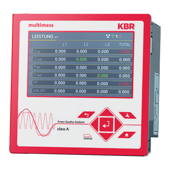
Display The colour display of the device provides information about the cor-rect connection of the measuring cables and trans- ducers and shows online data for voltages, currents, total harmonic distortion (THD), power values and energy. As well as the bar graphs for voltage and current harmonics. Pressing the "right“... - Page 61 Display page 2 Leiter-Leiter Spannungen & Ext- remwerte Leiter-Leiterspannung der gewählten Datenklasse in folgenden Zeiträumen 7 Tage Gesamte Messzeitraum, seit dem letzten Zurücksetzen The desired data class must be set via the setup display or the software (see section 6.5.4 Basic settings or section 7.5.3.9 Statistics)! The setting made is identical for all statistical values (maximum voltage...
- Page 62 Display page 4 Total active energy Active energy related (positive sign) Active energy supplied (negative sign) Total reactive energy Reactive energy referred (positive sign) Reactive energy supplied (negative sign) Display page 5 Current and current maximum of the selected data class in the following periods: of the last day of the last 7 days...
- Page 63 The break of the event counters is at 24:00 hrs at the change of day. Display page 8 Current firmware multimess F144-PQ Date & time from device Serial & article number Display page 9 Active device licence is displayed. Example device has a 40 kHz sampling...
- Page 64 Display page 10 SSH RSA Fingerprint of the Puplic Key of the PQI-DEs for verification of the connection via the software WinPQ lite / WinPQ. SSH ECDSA Fingerprint of the Puplic Key of the PQI-DEs for verification of the connec-tion via the software WinPQ lite / WinPQ.
- Page 65 6.4.2.1 Bar graph harmonics The following screen pages provide online information of the measured data in graphical form: Display page 1 The presentation of the bar graphs de- pends on the selected network type: Net type 4-wire: Bar graphs voltage harmonics H2 - H26 for L1, L2, L3 and Net type 3-wire: Bar graphs voltage harmonics H2 - H26 for L12, L23 and...
- Page 66 Display page 4 B ar graphs current harmonics H26 – H50 Display page 5 Bar graphs Voltage harmonics 2 - 9 kHz.. The bar graphs for the fre- quency bands 2 - 9 kHz are only displayed with device option B1. Display page 6 Bar graphs current harmonics 2 - 9 kHz..
- Page 67 6.4.2.2 Section detailed information Display page 1: Vector diagram Voltage vector U1E, U2E, U3E. Current vector I1, I2, I3 Additionally numeric display: Phase angle of the respective volt-age vector Phase shift current-voltage Display page 2: States of binary inputs and outputs State of eight binary inputs State of four binary outputs Display page 3: Level time diagram of residual current measurement...
-
Page 68: Pop-Up Display For Residual Current Measurement Messages
6.4.3 Pop-up display for residual current measurement messages According to DIN EN 62020, the task of a residual current monitor (RCM) is to monitor an electrical installation or circuit for the occurrence of a residual current and to indicate by means of an alarm if this exceeds a specified value. -
Page 69: Pop-Up Display Warning Message
6.4.3.2 Pop-up Display Warning Message Display Pop-up Display Warning Message If the set warning threshold is excee- ded (see chapter 6.5.2), a visual alarm message must appear on the display according to DIN EN 62020. In addition to the visual signal, a binary output can be swit- ched (see chapter 7.5.3.6). -
Page 70: Pop-Up Display Error Message
In this display, you can disable the RCM function until the error is corrected. The binary output can also be reset. After deactivating the RCM function, thes multimess F144-PQ restarts.. The error message is automatically reset when the error is corrected. -
Page 71: Setup Display
Setup display Pressing the key on the keypad will change the display to the setup menu. The following main menus are available in setup mode: 6.5.1 Parameter Parameter page 1... - Page 72 Net type Entering the grid type "3-conductor grid", "4-conductor grid" and/or "4 x 1 conductor grid" will determine how the Power Quality events are recorded. Switch between 3-conductor and 4-con- ductor grids. In a 3-conductor grid, all events are calculated from the line-line voltages. In a 4-conductor grid and/or a 4 x 1 conductor grid all Power Quality events are determined from the line-...
- Page 73 Reference channel The reference channel defines the measurement channel for frequency measurement and grid synchronisation. All phase angles are related to this channel. Power measurement The power calculation in the device firmware can be selected between two measurement functions: Power calculation according to DIN40110-Part 2 - with calculation of the unbalance reactive power.
-
Page 74: Residual Current Measurement / Rcm
6.5.2 Residual Current Measurement / RCM The RCM function is disabled by default. By pressing the "Enter" key the function can activated. When the RCM function is activated, the long-term recording and the fault record in case of overcurrent of the residual current are also activated automatically (see chapter 7.5.3.6 and chapter 7.5.4). - Page 75 Diff. current alarm threshold [mA] Definition of the alarm threshold Slope gradient [mA/kW] Optional definition of a coefficient for a linear slope of the thresholds. A detailed explana- tion can be found in chapter 7.4.9 Maximum threshold current [mA] Specification of the maximum threshold current when using the linear rise curve. Time delay RCM state change [s] Setting a time delay between the RCM state changes.
-
Page 76: Time Settings
6.5.3 Time settings The multimess F144-PQ has a variety of options for synchronising the time in the device to the world clock. KBR recommends selecting a high-precision time synchronisation variant in each case and also taking into account the quality of the time signal.. -
Page 77: Connection Dcf77 Radio Clock
6.5.3.2 Connection DCF77 radio clock It is recommended to use the COM2 interface as a time synchronisation interface. syn- chronisation interface. The following wiring is required to connect the DCF clock to the multimess F144-PQ wiring is necessary: picture clamp... -
Page 78: Manual Time Setting
6.5.3.4 Summer/winter time changeover (DST - Daylight Saving Time) If the summer time operating mode is set to internal, the summer/winter time changeover in the multimess F144-PQ takes place automatically every year. The multimess F144-PQ uses an internal algorithm with the following three parameters: Menu for setting the parameters for summer time changes. - Page 79 These parameters ensure for all future years that the changeover from summer to winter time is always carried out automatically by the multimess F144-PQ on the first Sunday on or after 1 April and the changeover from winter to summer time is always...
-
Page 80: Ntp Time Setting
6.5.3.5 NTP time setting The multimess F144-PQ has the possibility to synchronize itself with the Network Time Protocol (NTP) to an existing NTP server in the network. The used NTP server should be able to deliver a high time signal quality. -
Page 81: Nmea-Zda Time Setting
6.5.3.6 NMEA-ZDA time setting Setting up the RS232/RS485 interface for NMEA protocol 6.5.3.7 NMEA-RMC time setting Setting up the RS232/RS485 interface for NMEA protocol... -
Page 82: Irig-B Time Setting
IRIG-Bxx4-7 must be selected on the multimess F144-PQ and the time zone of the synchronised time must be speci- fied so that the multimess F144-PQ can save the measurement data internally with a correct UTC time stamp. The IRIG- BXX0..3 format does not provide any information on the current year;... -
Page 83: Ieee 1344 Time Setting
In addition to the IEEE1344 protocol, the interface must also be selected on the multimess F144-PQ and the time zone of the synchronised time must be specified so that the multimess F144-PQ can save the measurement data internally with a correct UTC time stamp. -
Page 84: Basic Setting
6.5.4 Basic setting Language: Select the display language Automatic setup: This function guides you through an automated device setup. This function is started automatically during initial commissioning and is not called up again afterwards. With "Autom. setup", the guided commissioning can be carried out again at any time. All data saved on the measuring device is deleted when the automatic setup is executed. -
Page 85: Password Lock Device Display
6.5.5 Password lock device display Access to the device setup can be disabled via a 4-digit password.. If a password is assigned, no access to the device set-up via the display is possible.. Enter your correct password Confirm with unlock Now the device setup over the keys and the display can be achieved. -
Page 86: Memory Management
SD memory card and releases the card for removal. 6.5.7 Setting up the device interfaces The multimess F144-PQ has a TCP/IP interface for communication with the WinPQ Lite or WinPQ client software. The necessary parameters can be set in the Interfaces menu. -
Page 87: Display
6.5.8 Display The display behavior of the PQI-DE can be adjusted in the Display menu. The multimess F144-PQ s delivered in the factory setting with the display brightness of 70%, a standby timeout of 900 seconds and the standby bright- ness in standby of 10%. -
Page 88: Display Lock
Display lock The device display of the multimess F144-PQ can be completely locked by pressing the key combination „Return“ and „Home“ five seconds When the lock is activated, the display of the device is switched off completely. It is no longer possible to view the display or the setup display. -
Page 89: Modbus
Endless counter for disturbance recorder and PQ-Events Read Coils Power Quality settings – write Modbus, only in contact with the support Modbus Datenpunktliste Über Modbus stehen über 10.000 Messwerte des multimess F144-PQ zur Verfügung. Auf Anfrage erhalten Sie die Datenpunktliste von unserem Support auch als Excel-Tabelle. -
Page 90: Modbus Settings
7.1.1 Modbus settings Settings of the Modbus TCP and Modbus RTU interface can be changed via the device setup. 7.1.2 Modbus RTU Settings for the Modbus TCP and Modbus RTU interfaces can be changed via the device setup. 7.1.3 Modbus TCP Modbus TCP is deactivated on delivery and can be activated here. -
Page 91: Set-Up Parameter Modbus With Winpq
7.1.4 Set-up parameter Modbus with WinPQ The WinPQ lite software can be used to change the settings of the Modbus TCP and Modbus RTU interfaces can be changed. Activation takes place via the TCP or RTU server activated parameter (0 = OFF / 1 = ON). Parameter serial: TCP server activated Activation of Modbus TCP... -
Page 92: Byte Order
7.1.5 Byte Order According to the Modbus specification, data are transmitted in the byte order Big-Endian. Regarding a 16-bit Modbus register, the data on the client side is interpreted without conversion. The following example illustrates this with the example value 0x1A2B: Address Communication Client-Side... -
Page 93: Data Bits
By default, a Modbus package with 8 data bits and one stop bit is set up on the measu- ring device. 7.1.8 Data types The Modbus implementation in the multimess F144-PQ currently works with the following data type.. Unsigned integer 32 bit (uint32_t) This data type stores unsigned integer values. - Page 94 Bit- Meaning Bit- Meaning Number Number RVC, Voltage U1E Dip, Voltage U12 Dip, Voltage U1E Swell, Voltage U12 Swell, Voltage U1E Interruption, Voltage U12 Interruption, Voltage U1E Overload, Voltage U12 Overload, Voltage U1E RVC, Voltage U23 RVC, Voltage U2E Dip, Voltage U23 Dip, Voltage U2E Swell, Voltage U23 Swell, Voltage U2E...
- Page 95 Sub seconds (tmFracSec_t) The sub second value has a width of 32 bits and is accordingly stored in two registers. The data type is based on the time format, which is defined in IEEE C37.118. The meaning of the individual bits is listed in the following table:: Bit- Meaning Number...
-
Page 96: Webserver
Webserver A web server is implemented on the measuring device, which can be used to download the proprietary recording files can be downloaded from the device. Parameterisation The web server is deactivated by default and must first be activated via the parameterisa- tion in the expert view of WinPQlite. -
Page 97: Measurement Data - Measurement Methods Multimess F144-Pq
Ripple control signal U Ripple Control (200 ms) In the multimess F144-PQ setup any interharmonic can be set. This is displayed as the 200 ms maximum value within a measurement interval.. Flicker levels P The Short term flicker levels Pst (10 min) and Long term flicker levels Plt (2 h) are calcula- ted for the star and delta voltages. - Page 98 THD – PWHD – K factorr Total harmonic content, calculated using the following formulae in accordance with IEC61000-4-7. Calculating the THD values of the voltages and signal sampling: – H2 up to H40 (based on EN50160) – H2 up to H50 (based on IEC61000-x-x) THD voltage: THD current in %: THD(A) current in Ampere:...
- Page 99 The determination of the harmonics and interharmonics interval values displayed using the methods of the IEC61000-4-30 Class A standard based on 10/12 period values. The multimess F144-PQ recognizes for all voltage and current channels, respectively, the harmonics up to the 50th ordinal. To evaluate the interharmonics, harmonic subgroups are created.
- Page 100 The harmonics for n = 0...50 are calculated. Voltage harmonics (standardized, 10/12 periods): Current harmonics: Reactive power / Reactive energy In the setup of the device two variants of the power calculation are adjustable Simplified power calculation Reactive power without unbalanced reactive power calculation: Reactive power calculation according DIN40110 part 2 Reactive power calculation with unbalanced power: Reactive energy::...
- Page 101 Distortion reactive power - D The distortion-reactive power - also called harmonic oscillation power - describes a special form of reactive power caused by alternating and three-phase current through nonlinear loads such as rectifiers in power supplies. The harmonics of the current in com- bination with the mains voltage give reactive power components, which are referred to as distortion-blocking powers.
- Page 102 Collective apparent power n. DIN 40110: 4-Leiter-Netz : 3-Leiter-Netz, I1 + I2 + I3 ≠ 0 : Geometrische Grundschwingungs-Scheinleistung : Collective apparent power n. DIN 40110: The sign of the active power corresponds to the direction of flow of the fundamental active energy (+: output, - : reference).
- Page 103 The collective effective power is defined for 3-wire systems as Fundamental oscillation - active power (line): = Geometric fundamental oscillation apparent power Symmetric Components The complex symmetrical components are calculated from the corresponding complex spectral components of the fundamental oscillations of the phase voltages and phase currents. Phase voltage in a 4-wire system = Phase-to-Neutral voltage Phase voltage in a 3-wire system = Phase-to-Ground voltage –...
- Page 104 Unbalance The unbalanced voltages are calculated from the corresponding values of the modal positive sequence, negative sequence and zero sequence components. For the EN50160 (events) only the voltage unbalance uu is relevant and corresponds to the ratio of the negative sequence to the positive sequence. The value is expressed in [%]. Frequency analysis 2 kHz to 20 kHz In the frequency analysis 2 kHz to 20 kHz respectively 200 Hz frequency bands are sum- marized.
-
Page 105: Service
This unit is maintenance-free for customers. Risk of death due to electric shock! DANGER! Do not open the unit. Maintenance of the device must only be carried out by KBR. For service, contact Service adrdess: KBR Kompensationsanlagenbau GmbH... - Page 106 Notizen...
- Page 107 Notizen...
- Page 108 KBR Kompensationsanlagenbau GmbH Am Kiefernschlag 7 T +49 (0) 9122 6373 - 0 www.kbr.de D-91126 Schwabach F +49 (0) 9122 6373 - 83 E info @ kbr.de...
Need help?
Do you have a question about the multimess F144-PQ and is the answer not in the manual?
Questions and answers