
Subscribe to Our Youtube Channel
Related Manuals for KBR Multimess F96-***-5 Series


Summary of Contents for KBR Multimess F96-***-5 Series
- Page 1 Quick guide Technical parameters Three-phase network measuring device multimess F96-...-5 Your partner for network analysis System English...
-
Page 2: Table Of Contents
Device overview ....... 18 Changing the bus parameters ... 33 Operating structure ......18 Ethernet interface for KBR eBus TCP ....... 34 Basic device programming ... 20 Main menu Extras ......34 Setting the limits ......20 Changing the bus parameters .. 34 Technical data in multimess F96-...-5 ...... - Page 3 KBR multimess F96-...-5 Dear customer Thank you for choosing a KBR product. To familiarize yourself with the operation and configuration of the device, we recommend that you read this manual carefully. This will enable you to make use of the full range of functions that this high-quality product has to offer.
- Page 4 KBR multimess F96-...-5 Introduction This manual contains notes that must be observed for your personal safety and to prevent damage to the equipment. These notes are identifi ed by a warning sign or information symbol, depending on the degree of hazard they warn about.
- Page 5 Introduction KBR multimess F96-...-5 DANGEROUS VOLTAGE The applicable DIN/VDE regulations must be observed during installation! Connection to the mains, commissioning and operation of the device may only be carried out by qualifi ed personnel. Qualifi ed personnel as defi ned in the...
- Page 6 KBR multimess F96-...-5 Introduction Product liability You have purchased a high-quality product. Only components of the highest quality and maximum reliability are used. Each device is subject to long-term testing before delivery. For details on product liability, please refer to our general terms and conditions for electronic equipment.
-
Page 7: Device Memory
Aside from the multimess F96-0-… -5 entry level model, the load profi le (P+ P- / Q+ Q-) can be saved with all device versions and later read out via KBR eBus. Network voltage can be monitored in accordance with EN 61000-4-30. In case of a violation, the voltage and current history is saved and can be analyzed on the LCD display. -
Page 8: Connecting The Multimess F96
KBR multimess F96-...-5 Installation and electrical connection Connecting the multimess F96-...-5 Installation and assembly The applicable VDE regulations must be observed during installation! Before the device is connected to the power supply, check whether the local power supply conditions comply with the specifications on the nameplate. A faulty connection can destroy the device. - Page 9 Installation and electrical connection KBR multimess F96-...-5 CAUTION The control voltage as well as the applied measuring voltage of the device must be protected using a back-up fuse. When connecting the current transformers, pay attention to the direction of energy fl ow and the correct assignment to the voltage paths! Power supply: The electrical installation of the building must have a disconnec- tor or circuit-breaker for the power supply voltage.
- Page 10 KBR multimess F96-...-5 Installation and electrical connection For the wiring of the pulse output, we recommend that you only use shielded twisted pair cables to avoid interference (e.g. installation line I-Y(ST) Y 2 x 2 x 0.8 , with the shielding only connected on one side).
- Page 11 Installation and electrical connection KBR multimess F96-...-5 Asymmetry The rotary fi eld is displayed in the menu UPH-PH, submenu Angle / asym. The voltage asymmetry is displayed according to standard EN 6100-4-30:2003. Shows the asymmetric load of the three phase network.
-
Page 12: Connection Diagram
KBR multimess F96-...-5 Installation and electrical connection Connection diagram Rev. 5.00... -
Page 13: Terminal Assignment
Ensure that the output has the right polarity. The output signals can be processed by a maximum-demand monitor or a master central process control, for example. 90 (ground) Interface connection 91 (A) For KBR-eBus or Modbus communication. 92 (B): Rev. 5.00... -
Page 14: System Operation
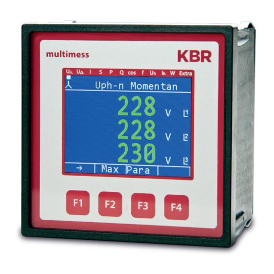
KBR multimess F96-...-5 System operation System operation In this chapter, you will find instructions on how to operate the multimess F96-...-5 in daily use. Furthermore, it contains references to the complete range of functions. Control and display panel multimess Extra... -
Page 15: Description Of Buttons And Displays
System operation KBR multimess F96-...-5 Description of buttons and displays 1 Display navigation panel The navigation panel shows the main menu selected, considerably simplifying operation of the device. The operator can immediately see what menu he is in. 2 Units display The DOT matrix display is normally used to show measured values. -
Page 16: Default Settings After A Reset (Delivery State)
KBR multimess F96-...-5 System operation Default settings after a reset (delivery state) Primary voltage/secondary voltage 400 V / 400 V Primary current/secondary current 5 A / 5 A Zero-point creator Measurement period time 15 minutes Current average time 10 minutes... -
Page 17: Setting Range
9990 pulses per KWH or kvar Energy pulse duration 30 to 990 milliseconds Signaling relay ON-delay 0 to 254 seconds Signaling relay shutdown delay 0 to 254 seconds Measurement period synchronization Internal, KBR eBus, for tariff switching Tariff switching Internal, KBR eBus Rev. 5.00... -
Page 18: Device Overview
KBR multimess F96-...-5 Device overview Device overview Operating structure The following gives you an overview of the entire operating structure at a glance. For a detailed description, please refer to “Menu overview”. Main menus Sub menus U PH-N U PH-N L1;... - Page 19 Device overview KBR multimess F96-...-5 Continuation of the operating structure Main menus Sub menus Frequency Min-max-values limits Para Modbus HARMON. U harm. U act. harm. U Harm Harm Harm Harm Harm Harm Harm Harm Harm up to Harm max. values max.
-
Page 20: Basic Device Programming
KBR multimess F96-...-5 Device overview Basic device programming The menu navigation of the multimess F96-...-5 is self-explanatory. The operator is guided and supported by the device through operating instruc- tions displayed for the respective situation. As an example of the basic configuration procedure, the functions in the U phase - N menu will be looked at more closely in the following. - Page 21 Device overview KBR multimess F96-...-5 After pressing the (G1) button, the following display appears in the hot key area of the display: Menu: U phase - N Return Uph-n limit 1 Change to processing of limit menu headline...
- Page 22 KBR multimess F96-...-5 Device overview After pressing the (EDIT) button, the following display appears in the hot key area of the display: Menu: U phase - N Return voltage transfor Scroll through lines in the menu headline...
-
Page 23: Technical Data In Multimess F96
Technical data KBR multimess F96-...-5 Technical data in multimess F96-...-5 Measuring and display values Wave form for U and I Voltage RMS value of a Phase - N: U L1-N L2-N L3-N measurement phase - phase: U L1-2 L2-3 L3-1... - Page 24 KBR multimess F96-...-5 Technical data Reactive Calculation -> ind. total power and cap. distinction between ind./cap. Units [Var; kvar; Mvar]; display is switched automatically. Measuring period 0.00VAr to 999Mvar memory Power factor Calculation -> ind. cosφ ; cosφ ; cosφ...
-
Page 25: Measurement Accuracy Class (In Accordance With Din En 61557-12)
Technical data KBR multimess F96-...-5 Measurement accuracy class (in accordance with DIN EN 61557-12) Measured value Symbol Accuracy class Voltage 0.5 / ± 1 digit Voltage 0.5 / ± 1 digit PHPH Phase current 0.5 / ± 1 digit Neutral conductor current measured 0.5 / ±... -
Page 26: Device Memory
KBR multimess F96-...-5 Device memory Energy, data and parameter 2 MB Flash memory Program memory 512 kB flash Memory type Ring buffer Long-term memory (1 year) Daily values for active and reactive energy (HT and LT) for consumption and recovery... -
Page 27: Hardware Inputs And Outputs
Interface RS485 for connection to the energy bus; max. 32 devices Baud rate 38400 fixed at KBR eBus, configurable with Modbus (option) Addressing Can be addressed automatically with software or manually on the device up to address 9999. For Modbus: 1 to 247 manually on the device. -
Page 28: Electrical Connection
KBR multimess F96-...-5 Technical data Electrical connection Connection elements Screw terminals Permissible cross-section 2.5 mm of the connecting cables Measure- Fuse protection max. 1 A slow-blow ment max. C2 automatic voltage isolating switch UL/IEC-approved inputs Measuring Fuse protection NONE!!! current... -
Page 29: Standards And Miscellaneous
Devices without Profibus DP DIN EN 61000-6-3:2011-09 + amendment 1:2012-11 Devices with Profibus DP DIN EN 61000-6-4:2011-09 Synchroniza- Type internal, rate switching or by KBR eBus tion Synchroniza- With internal synchronization based on the full hour tion time Rev. 5.00... -
Page 30: Modbus Interface
Description Modbus interface for Modbus RTU or ASCII The multimess F96-...-5 is optionally available with a Modbus RTU or ASCII in- terface. In order to use these, the device has to be converted from the KBR eBus to the Modbus RTU or ASCII bus protocol. - Page 31 Set Ebus parameters (address) Return Start the entry with the button and then change the bus protocol with by switch- ing from KBR eBus to Modbus. Menu heading Base para (2) Display hot-key area...
-
Page 32: Ethernet Interface For Modbus Tcp
KBR multimess F96-...-5 Modbus interface Use the button to call up the Modbus settings. Menu heading ModBus settings Display hot-key area EDIT Configuring the Modbus bus protocol Return By pressing , call up the settings menu for the Modbus address and bus protocol. -
Page 33: Main Menu Extras
Ethernet interface for Modbus TCP KBR multimess F96-...-5 Ethernet interface for Modbus TCP The multimess F96-...-5 is optionally available with an interface for Modbus TCP. Main menu Extras Menu heading Firmware info Display hot-key area ... -
Page 34: Ethernet Interface For Kbr Ebus Tcp
KBR multimess F96-...-5 Ethernet interface for Modbus TCP Ethernet interface for KBR eBus TCP The multimess F96-...-5 is optionally available with an interface for eBus TCP. Main menu Extras Menu heading Firmware info Display hot-key area ... -
Page 35: Profibus Dp Interface
Profi bus DP interface KBR multimess F96-...-5 Profi bus DP interface NOTE Availability of data points depends on the device version. Description profi bus DP interface The multimess 4F96 is optionally available with an interface for profi bus DP. In order to use this, the profi bus address has to be set up accordingly. - Page 36 KBR multimess F96-...-5 Profibus DP interface After pressing the button, the following display appears: Menu heading Bus Parameter Display hot-key area ProB Display / entry profibus address 1 to 126 Return After pressing the buttons, you can set the profibus address.
- Page 37 Notes KBR multimess F96-...-5 Rev. 5.00...
- Page 38 KBR multimess F96-...-5 Notes Rev. 5.00...
- Page 39 Notes KBR multimess F96-...-5 Rev. 5.00...
- Page 40 KBR Kompensationsanlagenbau GmbH www.kbr.de Am Kiefernschlag 7 T +49 (0) 9122 6373 - 0 D-91126 Schwabach F +49 (0) 9122 6373 - 83 Germany E info@ kbr.de...
Need help?
Do you have a question about the Multimess F96-***-5 Series and is the answer not in the manual?
Questions and answers