
Subscribe to Our Youtube Channel
Related Manuals for KBR multisio D6-ESBS-4RO-ISO-1


Summary of Contents for KBR multisio D6-ESBS-4RO-ISO-1
- Page 1 User Manual Technical Parameters multisio D6-ESBS-4RO-ISO-1 You can find the instructions for your KBR device at our download center. System English https://www.kbr.de/de/dienstleistungen/ download-center...
- Page 2 The individual chapters explain the technical details of the device and show how damage can be avoided through proper installation and commissioning. KBR Kompensationsanlagenbau GmbH does not accept any liability for any loss or damage resulting from printing errors in or changes to this manual.
-
Page 3: Table Of Contents
Table of Contents / Function description Table of Contents Function description of multisio D6-ESBS-4RO ISO-1 ..........3 Connection Diagram ......................4 Connection Variants of the Supply Voltage ..............5 Terminal assignment: ......................6 Function of Scan button ......................7 Manual Operation: ........................7 DIP Switch for Terminating RS-485 Interface: ...............8 Technical Data ...........................9 Environmental Conditions / Electrical Safety ............. -
Page 4: Connection Diagram
Connecting additional modules Connection Diagram module module module IN/OUT: Module bus/ supply voltage Modul Modul Modul IN/OUT: Modulbus/ Versorgungsspannung 93 94 95 eBus Interface: Klemme 93 eBus Ground multisio D6-4RO-1 ISO with eBus Klemme 94 eBus A Klemme 95 eBus B multisio D6-4RO-1 ISO mit eBus eBus Schnittstelle: Klemme 93 eBus Masse... -
Page 5: Connection Variants Of The Supply Voltage
Connecting additional modules Connection Variants of the Supply Voltage Safety device and dis- Voltage Terminal 1 Terminal 2 connector to Terminal 2 Power supply unit US1 required Neutral 100V - 240V +/-10% AC Phase L conductor N 50/60 Hz 100V - 240V +/-10% AC Phase L1 Phase L2 50/60 Hz... -
Page 6: Terminal Assignment
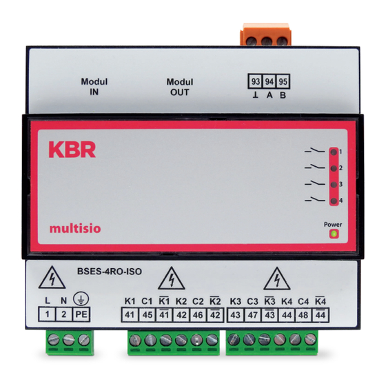
Terminal assignment Terminal assignment: Terminal 1: Phase (L) and DC (+) Mains Terminal 2: Neutral conductor and DC (-) Terminal PE: Protective earth Terminal 93: eBus ground eBus Terminal 94: eBus A Terminal 95: eBus B Terminal 41: NO = normaly open relay 1 Changeover relay A1: Terminal 45: Shared connection relay 1... -
Page 7: Function Of Scan Button
Function of Scan button / Manual Operation In scanning mode, all 4 output LEDs are flashing. In the module detection mode, the output LEDs generate a chase light effect. The LEDs represent: LED 1: Output relay 1 ( A1 ) switched LED 2: Output relay 2 ( A2 ) switched LED 3:... -
Page 8: Dip Switch For Terminating Rs-485 Interface
DIP Switch for Terminating RS-485 Interface: Output 1 Output 2 Output 3 Output 4 Relay state DIP S1 DIP S5 DIP S2 DIP S6 DIP S3 DIP S7 DIP S4 DIP S8 automatic manual passive / off manual active / on X: DIP switch state does not matter If necessary, the RS-485 interface on the module bus side can be terminated using four DIP switches (terminating resistors are fitted into multisio). -
Page 9: Technical Data
Hardware outputs Module bus Serial interface RS485 interface Module bus connec- RJ12 for ready-made tion KBR system cable, max. length 30 m when suitably placed Maximum DC power output 7W Transmission 38400 Bps speed Bus protocol KBR module bus/eBus optional... - Page 10 Technical Data Continuation of table Hardware Outputs 4 relay outputs 2 plug terminals, each 6-pin Changeover relay A1: Terminal 41 NO = normaly open relay 1 Changeover relay A1: Terminal 45 Shared connection relay 1 Changeover relay A1: Terminal 41 NC = normally closed relay 1 Changeover relay A2: Terminal 42 NO = normaly open relay 2...
-
Page 11: Environmental Conditions / Electrical Safety
Technical Data Environmental Conditions / Electrical Safety Surrounding Standards DIN EN 60721-3-3/A2: 1997-07; 3K5+3Z11; conditions (IEC721-3-3; 3K5+3Z11) Operating K55 (-5 °C …. +55 °C) temperature Air humidity 5 % … 95 %, non-condensing Storage K55 (-25°C …. +70°C) temperature Operating height 0…2,000 m above sea level Electrical Standards DIN EN 61010-1: 2011-07... - Page 12 KBR Kompensationsanlagenbau GmbH Am Kiefernschlag 7 T +49 (0) 9122 6373 - 0 www.kbr.de D-91126 Schwabach F +49 (0) 9122 6373 - 83 Germany E info @ kbr.de...
Need help?
Do you have a question about the multisio D6-ESBS-4RO-ISO-1 and is the answer not in the manual?
Questions and answers