TECO TK Series Installation Manual
Hide thumbs
Also See for TK Series:
- Manualline (15 pages) ,
- Replacement manuallines (11 pages) ,
- Replacement manualline (11 pages)

Related Manuals for TECO TK Series


Summary of Contents for TECO TK Series
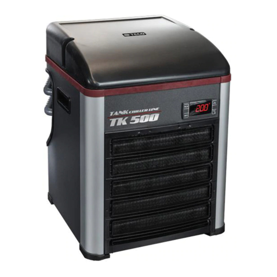
- Page 1 GUIDELINE HEATER INSTALLATION MODELS : TK500 – TK1000 – TK 2000 www.tecoonline.com www.tecous.com...
-
Page 2: Before Starting
BEFORE STARTING WARNING! Before mounting the heater, make sure to install only heaters suitable for chillers containing flammable gas (R290) How to make sure: 1) check the name of the gas indicated on the technical label situated at the back of the chiller. It can be R290 or R134A. 2) check the label on the Heater. - Page 3 EQUIPMENT AND INITIAL STEP EQUIPMENT Big Crosshead Screwdriver Small Crosshead Screwdriver SPARE PARTS Heater KRES02# (spare part) HEATER NYLON WASHER RING NUT Nylon washer 3.5.038 Ring nut 2.4.124 INITIAL STEP Turn OFF the chiller and let it OFF for twenty minutes before proceeding Disconnect the chiller from power supply Never touch internal part or dismount chiller when it is connected to...
- Page 4 STEP n. Remove the conveyor from the top part of the chiller. You can see the metal black grid and the red or grey fan support. Remove the air filter grid and air filter from their position. www.tecoonline.com www.tecous.com...
- Page 5 STEP n. Using the screw-driver, remove the 4 INOX screws indicated in the picture Remove the red or grey fan support lifting it up from the bottom edge. Leave it temporarily on the metal cover, as you can see in the picture.
- Page 6 STEP n. Disconnect: Power cable hot wire from wago connector (brown or black wire. See img.9-10-11) Power cable neutral wire from wago connector (blue or white POWER CABLE wire. See img.9-10-11) Power cable ground wire from wago connector (yellow-green or green wire. See img.9-10-11) Compressor cable connector (img.12) Probes green connector...
- Page 7 STEP n. Remove RJ45 cap and two little screws from wifi-panel (img.15-16-17). It’s now possible to remove the red or grey fan support. Please see img.18. www.tecoonline.com www.tecous.com...
- Page 8 STEP n. Unscrew the white cap and remove it from the top of the exchanger (img.19) Place the heater inside the exchanger (img.21). Don’t forget the nylon washer (img.20). Screw very well the ring nut (img.22) Connect the heater to the cable NYLON EPDM assembly that you find in the grey...
- Page 9 STEP n. Restore the wiring in the following order: 1) Wifi connector into chiller metal cover (two little screws) 2) Compressor connector 3) Probe connector 4) Hot, neutral and ground wires of power cord into wago connector following already connected wires color (black or brown wire with other brown wire, white or blue wire to other blue wire and green or yellow-green wire to yellow-green wire)
- Page 10 STEP n. CHECKS IN WATER CIRCUIT Connect chiller joints to water pipes and turn on the pump. Check that there is required real water flow trough chiller exchanger. Minimum is 400 l/h for TK500 Minimum is 500 l/h for TK1000 Minimum is 600 l/h for TK2000 The real water flow is the effective flow of water that you find when aquarium is assembled (when pumps and pipes are connected to tank and chiller).
Need help?
Do you have a question about the TK Series and is the answer not in the manual?
Questions and answers