Sign In
Upload
Download
Table of Contents
Contents
Add to my manuals
Delete from my manuals
Share
URL of this page:
HTML Link:
Bookmark this page
Add
Manual will be automatically added to "My Manuals"
Print this page
×
Bookmark added
×
Added to my manuals
Manuals
Brands
ASROCK Rack Manuals
Motherboard
C2550D4I
User manual
ASROCK Rack C2550D4I User Manual
Server/workstation
Hide thumbs
1
2
3
Table Of Contents
4
5
6
7
8
9
10
11
12
13
14
15
16
17
18
19
20
21
22
23
24
25
26
27
28
29
30
31
32
33
34
35
36
37
38
39
40
41
42
43
44
45
46
47
48
49
50
51
52
53
54
55
56
57
58
59
60
61
62
63
64
65
page
of
65
Go
/
65
Contents
Table of Contents
Troubleshooting
Bookmarks
Table of Contents
Table of Contents
Chapter 1 Introduction
Package Contents
Speciications
Unique Features
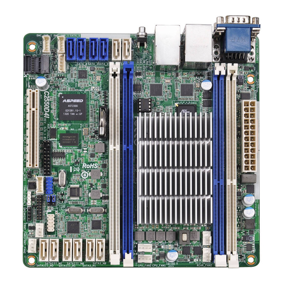
Motherboard Layout
I/O Panel
Block Diagram
Chapter 2 Installation
Screw Holes
Pre-Installation Precautions
Installation of Memory Modules (DIMM)
Expansion Slots (PCI Express Slots)
Jumper Setup
Onboard Headers and Connectors
Unit Identiication Purpose Led/Switch
Driver Installation Guide
Chapter 3 UEFI Setup Utility
Introduction
UEFI Menu Bar
Navigation Keys
Main Screen
Advanced Screen
Easy Raid Installer
Storage Coniguration
ACPI Coniguration
Super IO Coniguration
H/W Monitor Screen (Hardware Health Event Monitoring)
Intelrcsetup
Processor Coniguration
North Bridge Coniguration
South Bridge Chipset Coniguration
System Event Log
Server Management
Event Logs
Security Screen
Boot Screen
Exit Screen
Chapter 4 Software Support
Install Operating System
Support CD Information
Running the Support CD
Drivers Menu
Utilities Menu
Contact Information
Chapter 5 Troubleshooting
Troubleshooting Procedures
Technical Support Procedures
Advertisement
Quick Links
1
Jumper Setup
Download this manual
Table of
Contents
Previous
Page
Next
Page
1
2
3
4
5
Advertisement
Table of Contents
Need help?
Do you have a question about the C2550D4I and is the answer not in the manual?
Ask a question
Questions and answers
Related Manuals for ASROCK Rack C2550D4I
Motherboard ASROCK Rack C236 WSI User Manual
Mini itx motherboard (69 pages)
Motherboard ASROCK Rack C236 WSI4-85L Quick Installation Manual
(2 pages)
Motherboard ASROCK Rack C236 WSI4-85 Quick Installation Manual
(2 pages)
Motherboard ASROCK Rack C236 WSI4 Series User Manual
(72 pages)
Motherboard ASROCK Rack C246 WSI User Manual
(83 pages)
Motherboard ASROCK Rack C422 WSI/IPMI User Manual
(87 pages)
Motherboard ASROCK Rack C2750D4I User Manual
Server/workstation (65 pages)
Motherboard ASROCK Rack E3C246D4U User Manual
Server / workstation motherboard (87 pages)
Motherboard ASROCK Rack C236M WS User Manual
(77 pages)
Motherboard ASROCK Rack C3758D4U-2TP User Manual
Server/workstation motherboard (82 pages)
Motherboard ASROCK Rack C3558D4U-2OP User Manual
Server/workstation motherboard (82 pages)
Motherboard ASROCK Rack C236 WS User Manual
Server/workstation (79 pages)
Motherboard ASRock Rack EP2C612D16NM User Manual
Ep2c612d16nm series (99 pages)
Motherboard ASROCK Rack EPC621D4I-2M User Manual
(81 pages)
Motherboard ASROCK Rack E3C246D2I User Manual
(83 pages)
Motherboard ASROCK Rack X570D4I-2T User Manual
(31 pages)
This manual is also suitable for:
C2750d4i
C2 50d4i series
Table of Contents
Print
Rename the bookmark
Delete bookmark?
Delete from my manuals?
Login
Sign In
OR
Sign in with Facebook
Sign in with Google
Upload manual
Upload from disk
Upload from URL


Need help?
Do you have a question about the C2550D4I and is the answer not in the manual?
Questions and answers