Table of Contents
Advertisement
Quick Links
*15G065087100AK*
P/N: 15G065087100AK V1.0
Quick Installation Guide
C236 WSI4-85 / C236 WSI4-85L / C236 WSI4-65L
The server board User's Manual is available for download from the ASRock Rack's official website
at http://www.asrockrack.com.
Take note of the following precautions before you install server board components or change any
server board settings.
1.
Unplug the power cord from the wall socket before touching any components.
2.
To avoid damaging the server board's components due to static electricity, NEVER place your
server board directly on the carpet or the like. Also remember to use a grounded wrist strap or
touch a safety grounded object before you handle the components.
3.
Hold components by the edges and do not touch the ICs.
4.
Whenever you uninstall any component, place it on a grounded anti-static pad or in the bag
that comes with the component.
5.
When placing screws into the screw holes to secure the server board to the chassis, please do
not over-tighten the screws! Doing so may damage the server board.
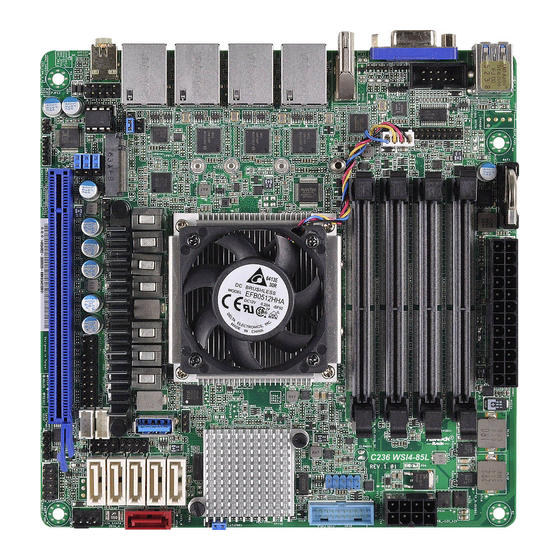
Motherboard Layout
2
1
2
3
17.0cm (6.7 in)
USB 3.0
T: USB3_1
B: USB3_2
COM1
1
1
TPM1
CPU_FAN1
HDMI1
LAN1
LAN2
LAN3
37
LAN4
NMI_BTN1
1
1
M2_1
SEC_OR1
36
CHASSIS_ID0
1
CHASSIS_ID1
35
1
1
CHASSIS_ID2
1
34
HD_AUDIO1
33
32
HDMI_SPDIF1
LED_LAN_3_4
1 1
1 1
31
30
3
I/O Panel
1
3
4
5
2
No. Description
No. Description
1
USB 3.0 Port (USB3_2)
6
2
USB 3.0 Port (USB3_1)
7
3
VGA Port (VGA1)
8
4
HDMI Port
9
5
LAN RJ-45 Port (LAN1)
4
CMOS
ATXPWR1
Battery
DDR4_B2 (64 bit, 260-pin module)
DDR4_B1 (64 bit, 260-pin module)
DDR4_A2 (64 bit, 260-pin module)
DDR4_A1 (64 bit, 260-pin module)
T 1
R
1
1
PCIE7
29
27
28
6
7
8
9
LAN RJ-45 Port (LAN2)
LAN RJ-45 Port (LAN3)
LAN RJ-45 Port (LAN4)
Front Speaker (Lime)
1
Install the Server Board
1
Insert the server board into the chassis.
2
A f f i x t he screws clock w ise into t he
mounting holes in all of the corners of
the server board.
Do not over-tighten the screws
CON1
USB3_3_4
1
CLRMOS1
1
USB_1_2
PCH
SATA_1
SATA_2
SATA_3
SATA_SGPIO1
1
SATA_4
SATA_SGPIO2
SATA_PWR1
AUX_PANEL1
1
SATA_5
SATA_PWR2
1
1
FRNT_FAN1
PLED PWRBTN
SPEAKER1
1
PANEL1
1 1
HDLED RESET
26
24
23
25
22
4
Jumper Cap On/Off
When the jumper cap is placed on the pins, the
jumper is "Short". If no jumper cap is placed on the
pins, the jumper is "Open".
The illustration shows a 3-pin jumper whose pin1
and pin2 are "Short" when a jumper cap is placed on
these 2 pins.
www.asrockrack.com
No.
Description
1
COM Port Header (COM1)
2
TPM Header (TPM1)
3
CPU Fan Connector (CPU_FAN1)
4
ATX Power Connector (ATXPWR1)
5
12V DC Input Power Connector (CON1)
5
2 x 260-pin DDR4 SO-DIMM Slots
6
(DDR4_A2, DDR4_B2)
6
2 x 260-pin DDR4 SO-DIMM Slots
7
7
(DDR4_A1, DDR4_B1)
8
8
USB 2.0 Header (USB_1_2)
9
USB 3.0 Header (USB3_4_5)
9
10
Clear CMOS Pad (CLRMOS1)
11
SATA DOM Power Jumper (SATAPWR1)
10
12
Vertical Type A USB 3.0 (USB3_5)
13
SATA SGPIO Connector (SATA_SGPIO1)
14
SATA3 Connector (SATA_1)
15
SATA3 Connector (SATA_2)
11
16
SATA3 DOM Connector, (SATA_0), Red
1
12
17
SATA3 Connector (SATA_3)
13
14
18
SATA3 Connector (SATA_4)
15
19
SATA3 Connector (SATA_5)
16
20
Front Fan Connector (FRNT_FAN1)
17
18
21
System Panel Header (PANEL1)
19
22
Speaker Header (SPEAKER1)
20
23
SATA SGPIO Connector (SATA_SGPIO2)
21
24
SATA DOM Power Header (SATA_PWR2)
25
SATA DOM Power Header (SATA_PWR1)
26
Auxiliary Panel Header (AUX_PANEL1)
27
PCI Express 3.0 Card Slot 7 (PCIE7)
28
M.2 Socket (M2_1)
29
Thermal Sensor Header (TR1)
30
LAN LED Connector (LED_LAN_3_4)
31
HDMI SPDIF Header (HDMI_SPDIF1)
32
Chassis ID2 Jumper (CHASSIS_ID2)
33
Chassis ID1 Jumper (CHASSIS_ID1)
34
Chassis ID0 Jumper (CHASSIS_ID0)
35
Front Panel Audio Header (HD_AUDIO1)
36
ME Recovery Jumper Jumper (SEC_OR1)
37
Non Maskable Interrupt Button (NMI_BTN1)
Advertisement
Table of Contents

Related Manuals for ASROCK Rack C236 WSI4-85L


Summary of Contents for ASROCK Rack C236 WSI4-85L
-
Page 1: Motherboard Layout
C236 WSI4-85 / C236 WSI4-85L / C236 WSI4-65L www.asrockrack.com Install the Server Board The server board User's Manual is available for download from the ASRock Rack's official website at http://www.asrockrack.com. Take note of the following precautions before you install server board components or change any Insert the server board into the chassis. - Page 2 Quick Installation Guide C236 WSI4-85 / C236 WSI4-85L / C236 WSI4-65L www.asrockrack.com Install the Power Cables LAN Port LED Indications LAN Port ACT/LINK LED SPEED LED LAN Port Activity / Link LED Speed LED Status Description Status Description No Link...
Need help?
Do you have a question about the C236 WSI4-85L and is the answer not in the manual?
Questions and answers