Table of Contents
Advertisement
Quick Links
Advertisement
Table of Contents

Related Manuals for Pilz PMCtendo SZ


Summary of Contents for Pilz PMCtendo SZ
- Page 1 PMCtendo SZ Pilz Motion Control Operating Manual1002405EN03...
- Page 2 Preface This document is a translation of the original document. All rights to this documentation are reserved by Pilz GmbH & Co. KG. Copies may be made for internal purposes. Suggestions and comments for improving this documentation will be gratefully received. Pilz®, PIT®, PMI®, PNOZ®, Primo®, PSEN®, PSS®, PVIS®, SafetyBUS p®, SafetyEYE®, SafetyNET p®, the spirit of safety® are registered and protected trademarks of Pilz GmbH & Co. KG in some countries. SD means Secure Digital...
-
Page 3: Table Of Contents
3 Description ......3.1 PMCtendo SZ servo motors...... - Page 4 9.4 Cooling......... . Operating Manual PMCtendo SZ...
- Page 5 Key safety-related indicators ....10 Glossary ....... . Operating Manual PMCtendo SZ 1002405-EN-03...
-
Page 6: Introduction
1 Introduction Introduction Purpose of the manual This operating manual describes the servo motors PMCtendo SZ. It includes information about, transport, storage, installation, connection, commissioning, service and disposal. Please also refer to the documentation for the servo amplifier. Further support If you have any queries that are not covered in this document, you can find more infor- mation at www.pilz.com... -
Page 7: Notes On Safety
The following is deemed improper use: • direct connection to the mains power supply, • any component, technical or electrical modification, • use outside the areas described in this manual, • use outside the documented technical details. Operating Manual PMCtendo SZ 1002405-EN-03... -
Page 8: Qualified Personnel
Directives and norms The servo motors meet the following guidelines and norms • Directive 2006/95/EC (Low Voltage Directive) • Directive 2004/108/EC (Directive on Electromagnetic Compatibility) • DIN EN 60204-1 version 2007 • DIN EN 60034-1 version 2011 Operating Manual PMCtendo SZ 1002405-EN-03... -
Page 9: Presentation Of Notes On Safety
This means that a minor injury may occur. if the safety precautions stated are not observed. WARNING! Warning means that there may be a serious danger of death if the stated precautionary measures are not taken. Operating Manual PMCtendo SZ 1002405-EN-03... - Page 10 if the stated precautionary measures are not taken. INFO refers to important information about the product or serves to emphasize a section in the documentation to which the reader should pay special atten- tion. Operating Manual PMCtendo SZ 1002405-EN-03...
-
Page 11: Description
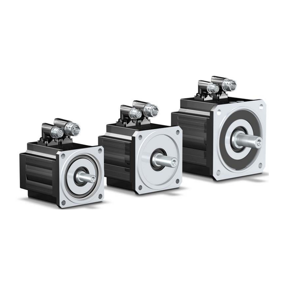
Description PMCtendo SZ servo motors The PMCtendo SZ synchronous servo motors have a very short design achieved thanks to an optimized winding technology. This feature makes it possible to manufacture the stator windings with the highest possible copper fill factor. With this technology and fur- ther optimizations in the mechanical parts it has been possible to shorten the length of the motor by almost half without reducing the power output. -
Page 12: Type Label
Type label Description Value in example Meaning Year of YOM 2014 Year of manufacturing 2014 Manufacturing Type PMCtendo SZ.31/0/1/2/7/K/H/60/00 Order references 7008874/001/000/010/00 Serial number Ident.No. xxxxxxx Identification number Standstill torque: Constant standstill torque for 0,95 Nm 250 min ±... -
Page 13: Order Reference
3000 min of inertia 4500 min (not applicable for SZ.3x, SZ.51, SZ.71) 6000 min 4 Feedback Code 10 Option Code Single-turn EnDat® 2.2 ECI1118-G2 Standard inductive Multi-turn EnDat® 2.2 EQN1135 optical a) See section Type-specific data Operating Manual PMCtendo SZ 1002405-EN-03... -
Page 14: Drive Controller
Dynamic performance The PMCtendo SZ motors are designed as standard for applications with high dynamic performance, i.e. they have the lowest possible mass moment of inertia. As an option the servo motors can be supplied with an increased mass moment of inertia in order to opti- mize the inertia ratio between motor and load. -
Page 15: Thermal Winding Protection
The servo motors have a thermal winding protection, which protects the stator winding from damage in the case of constant overload. The PMCtendo SZ motors are fitted with PTC drilling as standard. If the motor tempera- ture reaches a critical level, the ohmic resistance of the PTC resistors increases abruptly and this indicates motor overload. -
Page 16: Brake Test And Grinding
The servo motors have a smooth shaft end (DIN 6885) on the drive side. With a friction connection, torque transfer must be achieved through surface pressure. This guarantees a safe, backlash-free force transfer. The bearings are designed as ball bearings with permanent lubrication and non-contact seals. Operating Manual PMCtendo SZ 1002405-EN-03... -
Page 17: Transportation And Storage
Protect the motor shaft from corrosion when storing over an extended period. Note that the insulation resistance of the winding must be checked after storing over an extended period. Operating Manual PMCtendo SZ 1002405-EN-03... -
Page 18: Installation
Ensure adequate heat dissipation. Ensure compliance with the admissible ambient temperature. If necessary, cool the servo motor additionally, e.g. using an external fan. • Observe the minimum clearance to the air intake of an external fan. Operating Manual PMCtendo SZ 1002405-EN-03... -
Page 19: Install Motor
Do not apply any pressure, impact or high acceleration to the motor. Use backlash-free, frictionally engaged chucks or clutches. Always use the tightening thread provided in the motor shaft to fit or remove clutches, gears or belt pulleys. Use suitable tools! Operating Manual PMCtendo SZ 1002405-EN-03... - Page 20 Prevent temperature-sensitive components coming into contact with the motor. During operation, the surface temperature of the servo motor can exceed 65 °C! • When removing the eye bolts after installation, permanently close the threaded hole according to the protection class of the motor. Operating Manual PMCtendo SZ 1002405-EN-03...
-
Page 21: Electrical Installation
Observe the applicable regulations. General information 6.1.1 Wiring Observe the regulations applicable for your machine or system when installing the elec- trical equipment, e.g. DIN IEC 60364 or DIN EN 50110. Operating Manual PMCtendo SZ 1002405-EN-03... -
Page 22: Earthing, Shielding And Emc
An appropriate connection material should be used to connect the cable shield to the earth bar or bus bar (e.g. shielded terminals, see Fig. 6-1: ). Fig. 6-1: Cable shield connection using a shielded terminal on the earth bar (reproduced with permission from icotek GmbH, www.icotek.de) Operating Manual PMCtendo SZ 1002405-EN-03... -
Page 23: Selecting The Cables
Requirement: You have removed the protection caps from the angular flange sockets. Connect the cable to the speedtec ® plug connector Align the union nut so that the arrow faces the union nut and angular sock- Operating Manual PMCtendo SZ 1002405-EN-03... - Page 24 Connect the cable with springtec® plug connector Align the respective union nuts of the green encoder plug and the orange power connector so that the points on the union nuts and the angle con- nection socket are facing each other: Operating Manual PMCtendo SZ 1002405-EN-03...
- Page 25 6 Electrical installation Connect the union nuts directly onto the angle connection socket: Operating Manual PMCtendo SZ 1002405-EN-03...
-
Page 26: Servo Motor And Motor Brake
Servo motor and motor brake 6.2.1 Power cable PMCtendo SZ servo motors will be connected to the drive controllers via the following power cables (the colour specifications apply to the connection strands and are only rel- evant for the motor wiring). - Page 27 6 Electrical installation Power cable – connector sizes con.40, con.58 Angular flange socket – motor Pin Signal Colour 1BR+ (brake + 24 VDC) – 1BR– (brake 0 V) GNYE Housing Shield Operating Manual PMCtendo SZ 1002405-EN-03...
-
Page 28: Assignment: Motor And Power Cable
INFO Note that the following assignment of the connector size to the minimum cross-section ø refers to a maximum cable length of 100 m. PMCtendo SZ – convection-cooled (PMCtendo SZ.xx/.../K/...) = 2000 min = 3000 min = 4500 min = 6000 min... - Page 29 6 Electrical installation PMCtendo SZ – externally ventilated (PMCtendo SZ.xx/.../F/...) = 2000 min = 3000 min = 4500 min = 6000 min Motor Connec- ø Connec- ø Connec- ø Connec- ø tor size tor size tor size tor size SZ.41 —...
-
Page 30: Feedback
6 Electrical installation Feedback PMCtendo SZ servo motors will be connected to the feedback systems single-turn/multi- turn EnDat® 2.2 optical/inductive via the following feedback cables (the colour specifica- tions apply to the connection strands and are only relevant for the motor wiring). -
Page 31: External Fan
Signal — Water cooling Connect the water cooling to the hose connectors G1/8" (fittings). Connection is possible on the connector side or opposite. Observe the specifications for the cooling circuit, see section 9.4.3 Water cooling. Operating Manual PMCtendo SZ 1002405-EN-03... -
Page 32: Commissioning
Check that the rotor of the servo motor can turn freely. If a motor brake is provided, this must be ventilated be- fore the test. Observe the polarity of the connections when doing this! Operating Manual PMCtendo SZ 1002405-EN-03... -
Page 33: Check Connection
Control the servo motor using the servo amplifier. Please refer to the documentation for the servo ampli- fier. Check the function of the motor brake. Apply the control voltage to the motor brake (ensure correct polarity): The motor brake must release. Operating Manual PMCtendo SZ 1002405-EN-03... -
Page 34: Put Into Operation
The following table lists typical faults that can affect the servo motor during commission- ing. Further sources of faults can be: • The servo amplifier • A higher-level controller • Integration of the motor into a multi-axis system Take care therefore to also observe the respective documentation! Operating Manual PMCtendo SZ 1002405-EN-03... - Page 35 Check dimensioning of the motor engage brake Motor brake defective • Replace motor Motor shaft with axial overload • Check axial load and reduce, if neces- sary; also replace motor because the bearings are damaged Operating Manual PMCtendo SZ 1002405-EN-03...
-
Page 36: Service
Cordon off the installation area according to the safety regulations, e.g. with barriers, warning signs. INFO Note that repairs must only be carried out by Pilz GmbH & Co. KG. If the ser- vo motor is opened without authorisation and handled improperly, the war- ranty will be rendered invalid. -
Page 37: In The Event Of Disruptions
Check the ball bearings for noises; in the Note that the ball bearings may only be event of a deterioration, send in the servo replaced by Pilz GmbH & Co. KG! motor for replacement of the ball bear- ings, if necessary... -
Page 38: Replace Motor
Check the insulation resistance of the winding of the motor after storing over an ex- tended period. • Please refer to the information in 5 Installation. • Once the unit has been exchanged, restore the reference to the machine coordinate system. Operating Manual PMCtendo SZ 1002405-EN-03... -
Page 39: Technical Data
True running accuracy tolerance N in accordance with DIN 42955 Coaxiality tolerance N in accordance with DIN 42955 Axial run-out N in accordance with DIN 42955 Noise level Limit values in accordance with EN 60034-9 Operating Manual PMCtendo SZ 1002405-EN-03... -
Page 40: Electrical Data
External fan Motor SZ.4x SZ.5x SZ.7x SZ.8x 230 V, -10% to +6%, 50/60 Hz 230 V, ±10 %, 50/60 Hz 0.07 G [dBA] m [kg] [mm] F min Protection class IP 44 Maximum ambient temperature 60°C Operating Manual PMCtendo SZ 1002405-EN-03... -
Page 41: Water Cooling
SZ.5: 4.5 l/min SZ.7: 5 l/min SZ.8: 5 l/min Nominal coolant flow rate SZ.4: 6 l/min SZ.5: 6 l/min SZ.7: 7.5 l/min SZ.8: 7.5 l/min Installation height ≤ 1000 m above sea level, no derating possible Operating Manual PMCtendo SZ 1002405-EN-03... -
Page 42: Feedback
9 Technical data Feedback EnDat® 2.2 ECI1118-G2 single-turn inductive (type PMCtendo SZ.xx/x/1) Protocol EnDat® 2.2 Resolution per revolution 262 144 (18 bit) Operating voltage range 3,6–14 V Power consumption 3.6 V: ≤ 520 mW 14 V: ≤ 600 mW EnDat® 2.2 EQN1135 multi-turn optical (type PMCtendo SZ.xx/x/2) Protocol EnDat®... -
Page 43: Holding Brake
Holding brake Motor Bstat Bdyn B,Rlim B,Rmax/h B,NOT B,NOT — SZ.31 24 ± 5 % 0.51 48000 0.752 SZ.32 24 ± 5 % 0.75 38000 0.952 SZ.33 24 ± 5 % 0.75 30000 1.17 SZ.41 24 ± 5 % 0.75 16000 2.24 SZ.42... - Page 44 Motor Bremse Total mass moment of inertia [kgm Note section 9.9.1 Inertia. Mass moment of inertia – motor motor Mass moment of inertia – brake brake Speed [min Braking torque [Nm] Load torque [Nm] Operating Manual PMCtendo SZ 1002405-EN-03...
- Page 45 9 Technical data Stop time 2 66 ------------------------- 9 55 Stop time [ms] Operating Manual PMCtendo SZ 1002405-EN-03...
-
Page 46: Thermal Winding Protection
≥ 3990 Ω 145°C Thermal class (Limit temperature 155°C, warming ∆T = 100 K in accordance with DIN EN 60034/ VDE 0530) Thermal response time < 5 s Characteristic line of the individual PTC resistor Operating Manual PMCtendo SZ 1002405-EN-03... -
Page 47: Derating
The drive is to be installed at an altitude of 1500 m above sea level. According to the diagram, the admissible torque is approx. 95% of the rated torque M at this altitude. Hence D = 0.95. Operating Manual PMCtendo SZ 1002405-EN-03... -
Page 48: Ambient Temperature
The drive should be operated at an ambient temperature of 50°C. According to the dia- gram, the admissible torque is approx. 91% of the rated torque M at this ambient tem- perature. We thus have a factor D = 0.91. Operating Manual PMCtendo SZ 1002405-EN-03... -
Page 49: Type-Specific Data
25 285 285 SZ.7x 0,03 25 285 285 SZ.8x 0,03 Ensure that comparable thermal mounting conditions exist in your system! PMCtendo SZ motors – number of motor poles Motor Number of poles – PZ [1] SZ.3x SZ.4x SZ.5x SZ.7x SZ.8x... - Page 50 PMCtendo SZ motors IC410, convection-cooled (SZ.xx/.../K/...) Motor 0eff Vmin/ Nm/A Nm/A Ω 1000 SZ.31 6000 0,89 1,93 0,461 0,56 0,95 2,02 0,49 0,04 8000 12,7 11,7 39,8 SZ.31 3000 0,93 1,99 0,467 0,29 0,95 2,02 0,49 0,04 8000 12,7 11,7 39,8 SZ.32...
- Page 51 Motor 0eff Vmin/ Nm/A Nm/A Ω 1000 SZ.73 4500 12,1 11,5 1,052 17,8 1,137 0,24 6500 0,36 4,42 12,28 SZ.73 3000 16,5 11,4 1,447 20,8 1,503 0,24 6500 0,52 13,08 SZ.75 4500 16,4 14,8 1,111 25,2 0,24 6500 0,22 2,76 12,55 SZ.75 3000...
- Page 52 PMCtendo SZ motors IC416, externally ventilated (SZ.xx/.../F/...) Motor Vmin/ Nm/A Nm/A Ω 1000 SZ.41 6000 5,62 0,516 6,83 0,518 0,04 6500 1,94 11,52 5,94 SZ.41 3000 1,039 0,04 6500 16,5 37,7 5,63 SZ.42 6000 7,88 0,647 9,34 0,69 0,04 6500...
- Page 53 Motor Vmin/ Nm/A Nm/A Ω 1000 SZ.83 3000 35,9 1,365 66,7 42,3 1,584 4500 0,18 2,79 15,5 SZ.85 2000 77,2 45,2 1,708 53,9 1,749 4000 0,13 2,22 17,08...
- Page 54 PMCtendo SZ motors, water-cooled (SZ.xx/.../W/...) Motor 0eff Vmin/ Nm/A Nm/A Ω 1000 SZ.41 6000 2,55 0,49 3,35 6,95 0,488 0,04 6500 1,94 11,52 5,94 SZ.41 3000 0,892 3,55 0,921 0,04 6500 16,5 37,7 5,63 SZ.42 6000 0,625 6,45 0,669 0,04...
- Page 55 Motor 0eff Vmin/ Nm/A Nm/A Ω 1000 SZ.83 3000 46,7 34,1 1,37 65,7 41,7 1,583 4500 0,18 2,79 15,5 SZ.85 2000 72,1 42,1 1,713 90,1 51,9 1,742 4000 0,13 2,22 17,08...
- Page 56 9 Technical data Dimensioned drawing SZ motors IC410, convection cooled (SZ.xx/.../K/...) Without brake With brake With feedback system EnDat® optical Operating Manual PMCtendo SZ 1002405-EN-03...
- Page 57 13,5 M12 157 22 209 SZ.85 180j6 215 38k6 80 190 15 3,5 190 71 60 345 13,5 M12 157 22 291 CAD data can be found on the Internet at www.pilz.com or are available on request. Operating Manual PMCtendo SZ 1002405-EN-03...
- Page 58 9 Technical data Dimensioned drawing SZ motors IC416, with external fan (SZ.xx/.../F/...) Without brake With brake Operating Manual PMCtendo SZ 1002405-EN-03...
- Page 59 SZ.83 180j6 215 38k6 80 190 15 3,5 215 71 60 363 440 13,5 M12 156,5 134 184,0 40 SZ.85 180j6 215 38k6 80 190 15 3,5 215 65 60 445 522 13,5 M12 178 134 184,0 40 CAD data can be found on the Internet at www.pilz.com or are available on request. Operating Manual PMCtendo SZ 1002405-EN-03...
- Page 60 9 Technical data Dimensioned drawing SZ motors, water cooled (SZ.xx/.../W/...) SZ.4, SZ.7, SZ.8 SZ.5 Further dimensions, see dimensioned drawing SZ motors IC410, convection-cooled. Operating Manual PMCtendo SZ 1002405-EN-03...
- Page 61 70,5 10,5 SZ.55 70,5 10,5 SZ.71 72,5 10,5 SZ.72 72,5 10,5 SZ.73 72,5 10,5 SZ.75 72,5 10,5 SZ.82 SZ.83 SZ.85 CAD data can be found on the Internet at www.pilz.com or are available on request. Operating Manual PMCtendo SZ 1002405-EN-03...
-
Page 62: Inertia
0,93 0,192 SZ.42 1,63 0,566 SZ.44 2,98 SZ.51 — 0,571 SZ.52 SZ.53 7,58 1,721 SZ.55 12,2 SZ.71 — 1,743 SZ.72 13,7 SZ.73 21,6 5,68 SZ.75 13,6 SZ.82 14,9 16,46 SZ.83 83,5 22,3 SZ.85 37,2 55,46 Operating Manual PMCtendo SZ 1002405-EN-03... -
Page 63: Weight
9.9.2 Weight Motor ... with convection ... with externally venti- ... with water cooling ...with increased inertia ... with motor bake cooling (IC 410) lation (IC 416) ∆m ∆m [kg] SZ.31 — — — SZ.32 — — — 0,55 SZ.33 —... -
Page 64: Permitted Shaft Load
SZ.41 1800 SZ.42 1800 SZ.44 1800 SZ.51 2000 SZ.52 2400 SZ.53 2400 SZ.55 2400 SZ.71 1300 3500 SZ.72 1300 4200 SZ.73 1300 4200 SZ.75 1300 4200 SZ.82 1750 5600 SZ.83 1750 5600 SZ.85 1750 5600 Operating Manual PMCtendo SZ 1002405-EN-03... - Page 65 For speeds > 100 min decreases according to the following diagram: The diagram is based on the following formula: – 2ax n 100min ------------------------------------------- – 2ax n 100min ------------------------- - – 100min Operating Manual PMCtendo SZ 1002405-EN-03...
- Page 66 2radN The diagrams are based on the following formula: – 2RradN n 100min ---------------------------------------------------- - – 2RradN n 100min ------------------------- - – 100min Operating Manual PMCtendo SZ 1002405-EN-03...
- Page 67 9 Technical data For speeds > 100 min decreases according to the following diagrams: 2k,N Operating Manual PMCtendo SZ 1002405-EN-03...
- Page 68 9 Technical data Operating Manual PMCtendo SZ 1002405-EN-03...
- Page 69 100min ----------------------------------------------- - – 2k N n 100min ------------------------- - – 100min The following applies for an eccentric application of force: Motor SZ.3 SZ.4 19,5 SZ.5 19,5 SZ.7 24,5 SZ.8 28,5 Operating Manual PMCtendo SZ 1002405-EN-03...
-
Page 70: Voltage Limit Curves
= 3000 min The progression of these limit curves depends on a combination of the winding ver- sions (K factors) and the intermediate circuit voltage ends of the respective servo inverter. Operating Manual PMCtendo SZ 1002405-EN-03... - Page 71 9 Technical data PMCtendo SZ.31 PMCtendo SZ.32 Operating Manual PMCtendo SZ 1002405-EN-03...
- Page 72 9 Technical data PMCtendo SZ.33 PMCtendo SZ.41 Operating Manual PMCtendo SZ 1002405-EN-03...
- Page 73 9 Technical data PMCtendo SZ.42 PMCtendo SZ.44 Operating Manual PMCtendo SZ 1002405-EN-03...
- Page 74 9 Technical data PMCtendo SZ.51 PMCtendo SZ.52 Operating Manual PMCtendo SZ 1002405-EN-03...
- Page 75 9 Technical data PMCtendo SZ.53 PMCtendo SZ.55 Operating Manual PMCtendo SZ 1002405-EN-03...
- Page 76 9 Technical data PMCtendo SZ.71 PMCtendo SZ.72 Operating Manual PMCtendo SZ 1002405-EN-03...
- Page 77 9 Technical data PMCtendo SZ.73 PMCtendo SZ.75 Operating Manual PMCtendo SZ 1002405-EN-03...
- Page 78 9 Technical data PMCtendo SZ.82 PMCtendo SZ.83 Operating Manual PMCtendo SZ 1002405-EN-03...
-
Page 79: Key Safety-Related Indicators
Safety-related indicators – feedback Type Operating mode MTTF (in years) Sensor, ECI1118-G2 rotary encoder absolute Sensor, EQN1135 rotary encoder absolute Safety-related indicators – brake Type Operating mode (in operating cycles) Brake Actuator, PM brake 20000000 Operating Manual PMCtendo SZ 1002405-EN-03... -
Page 80: Glossary
Permitted constant current in the reference point, dependent on the winding version k for servo motors Inertia Total inertia Total inertia of a system Reference moment of inertia Smax Reference moment of inertia for the maximum permitted stops specified Operating Manual PMCtendo SZ 1002405-EN-03... - Page 81 Winding inductance between two phases (determined in the res- onant circuit procedure) Mass Torque Standstill torque Constant torque at 10 min , tolerance ± 5 %. Breakdown torque Permitted breakdown torque Existing breakdown torque Braking torque Operating Manual PMCtendo SZ 1002405-EN-03...
- Page 82 Frictional torque that develops in the bearings and seals at an operating temperature of 100°C. Torque for water cooling Number of emergency stops Maximum permitted number of stops at 3000 min Smax = 0. Maximum speed Rated speed Bedienungsanleitung PMCtendo SZ 1002405-DE-03...
- Page 83 Describes the current increase of a motor at 20°C, calculated from R and L Maximum permitted friction work up to wear limit Maximum permitted friction work for one braking action per hour max 1/h Minimum distance Fmin Operating Manual PMCtendo SZ 1002405-EN-03...
- Page 84 +49 711 3409-444 represented by our subsidiaries support@pilz.com and sales partners. Please refer to our homepage for further details or contact our headquarters. Pilz GmbH & Co. KG Felix-Wankel-Straße 2 73760 Ostfildern, Germany Telephone: +49 711 3409-0 Telefax: +49 711 3409-133 E-Mail: pilz.gmbh@pilz.de...
Need help?
Do you have a question about the PMCtendo SZ and is the answer not in the manual?
Questions and answers