Table of Contents
Advertisement
Instructions – Parts List
50:1 Fire-Ballr 425 Pumps
For pumping non–corrosive and non–abrasive
greases and lubricants only.
7500 psi (51.7 MPa, 517 bar) Maximum Working Pressure
150 psi (1.0 MPa, 10 bar) Maximum Air Input Pressure
Model 205394, Series E
Model 205395, Series N
Important Safety instructions
Read all warnings and instructions in this manual.
Save these instructions.
WARNING
This pump is designed to be used only in pumping
non-corrosive and non-abrasive oils and lubricants.
Any other use of the pump can cause unsafe operat-
ing conditions and component rupture, which can re-
sult in fluid injection or other serious injury or fire or
explosion.
GRACO INC. P.O. BOX 1441 MINNEAPOLIS, MN 55440-1441
Copyright 2002, Graco Inc. is registered to I.S. EN ISO 9001
306674U
06306B
Advertisement
Table of Contents

Related Manuals for Graco Fire-Ball 425 E Series


Summary of Contents for Graco Fire-Ball 425 E Series
- Page 1 06306B GRACO INC. P.O. BOX 1441 MINNEAPOLIS, MN 55440-1441 Copyright 2002, Graco Inc. is registered to I.S. EN ISO 9001...
-
Page 2: Table Of Contents
D This equipment is for professional use only. D Read all instruction manuals, tags, and labels before operating the equipment. D Use the equipment only for its intended purpose. If you are not sure, call your Graco distributor. D Do not alter or modify this equipment. - Page 3 WARNING SKIN INJECTION HAZARD Fluid from the gun, leaks, or ruptured components can inject fluid into your body and cause extremely serious injury, including the need for amputation. Fluid splashed in the eyes or on the skin can also cause serious injury. D Fluid injected into the skin is a serious injury.
- Page 4 D The air motor exhausts any fluids added to the input air. D Graco does not manufacture or supply the reactive chemical components that may be used in this equipment and is not responsible for injury or property loss, damage, expense, or claims (direct or consequential) that arise from the use of such chemical components.
-
Page 5: Installation
D Object being dispensed to: Follow your local code. NOTE: Always use Genuine Graco Parts and Acces- D Solvent pails used when flushing: Follow your local sories, available from your Graco distributor. - Page 6 Installation Mount the pump to suit the type of installation planned. WARNING Very heavy lubricants may require an inductor plate. See page 18 for the mounting hole layout and dimen- A bleed-type master air valve (B) is required to sions shut off and relieve air pressure that may be trapped in the air motor.
-
Page 7: Operation
Operation Startup and Adjustment WARNING Open the bleed-type master air valve. Open the dis- D This pump is designed to be used ONLY in pensing valve, and slowly open the air regulator until pumping non-corrosive and non-abrasive lubri- the pump is running smoothly. After all the air is cants and greases. -
Page 8: Troubleshooting
Troubleshooting Before servicing this equipment always make sure to WARNING Relieve the Pressure. To reduce the risk of serious injury whenever you are instructed to relieve pressure, always follow the Note: Check all possible problems and solutions Pressure Relief Procedure on page 7. before disassembling the pump. - Page 9 Notes 306674U...
-
Page 10: Displacement Pump Service
Displacement Pump Service Lips of v-packings Ref. 63 (copper gasket) and must face up Ref. 60} (cotter pin), Torque to 50 to 70 see Parts Drawing on page 16. ft-lb (68 to 95 N-m). 1/4” ROD 06336 } Included in Repair Kit 239320, which may be purchased separately. - Page 11 Displacement Pump Service 6. Hold the intake valve housing (67) with a wrench, WARNING and unscrew the priming tube (72) by inserting a 1/4 in (6 mm) diameter rod through the holes in the To reduce the risk of serious injury whenever you tube.
-
Page 12: Air Motor And Throat Service
Air Motor and Throat Service Before you Start 4. Remove the eight screws (7) holding the cylinder (32) to the base (56). Carefully pull the cylinder D Be sure you have all necessary parts on hand. Air straight up off the piston. See Fig. 4. Motor Repair Kit 207385 includes repair parts for the motor. - Page 13 Air Motor and Throat Service 6. Grip the toggle rockers (16) with a pliers. Com- NOTE: To remove the exhaust valve poppets press the springs (17) and swing the toggle (38*), stretch them out and cut with a sharp knife. assembly (K) up and away from the piston lugs 8.
- Page 14 Air Motor and Throat Service Reassembly Throat Packing Service 1. Clean all the parts carefully in a compatible solvent WARNING and inspect for wear or damage. Use all the repair kit parts during reassembly and replace other parts The piston in the air motor, located behind the air as necessary.
- Page 15 Air Motor and Throat Service 9. Reinstall the spacer and packing in the base and CAUTION packing nut (45{). Screw the packing nut into the base, and tighten it securely. Carefully slide the When reinstalling cotter pin (60}), always spread piston rod (52) down through the throat packing, and flatten the pin (both the head and prongs) and lower the piston into the base.
-
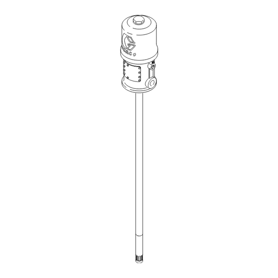
Page 16: Parts Drawing
Parts Drawing Model 205394, Series E 120 lb (55 kg) drum length Model 205395, Series N 400 lb (180 kg) drum length Torque to 45–55 ft–lb (61–75 N–m) 306674U... -
Page 17: Parts List
Parts List Model 205394, Series E 120 lb (55 kg) drum length Model 205395, Series N 400 lb (180 kg) drum length Air Motor Pump Part No. Description Qty. Part No. Description Qty. 207150 TRIP ROD 207391 PISTON 100170 BALL, steel; 3/8” dia. includes items 3 to 5 (also includes 100579 PIN, cotter;... -
Page 18: Dimensions
Dimensions 3/8 npt 3/8 npt Fluid Fluid Outlet Outlet 14–9/16” 14–9/16” (369.9 mm) (369.9 mm) 6–1/2” 6–1/2” (165.1 mm) (165.1 mm) Diameter Diameter 41–1/4” (1048 mm) 1/2 npt(f) 1/2 npt(f) 48–3/16” Air Inlet Air Inlet (1224 mm) 26–11/16” 33–5/8” (678 mm) (854.1 mm) Priming Piston Priming Piston... -
Page 19: Technical Data
Technical Data Fluid pressure ratio ................50:1 Air pressure operating range . -
Page 20: Graco Standard Warranty
With the exception of any special, extended, or limited warranty published by Graco, Graco will, for a period of twelve months from the date of sale, repair or replace any part of the equipment determined by Graco to be defective.
Need help?
Do you have a question about the Fire-Ball 425 E Series and is the answer not in the manual?
Questions and answers