
Related Manuals for Feig Electronic OBID i-scan RFID-Tunnel


Summary of Contents for Feig Electronic OBID i-scan RFID-Tunnel
- Page 1 ® APPLICATION NOTE OBID i-scan RFID-Tunnel (deutsch / english) preliminary public (B) 2007-08-27 N70101-2de-ID-B.doc...
- Page 2 ® OBID i-scan Applikations- Schrift RFID-Tunnel deutsche Version ab Seite 3 english version from page 30 FEIG ELECTRONIC GmbH Seite 2 von 54 N70101-2de-ID-B.doc...
- Page 3 Hinweise jederzeit dankbar. Die in diesem Dokument gemachten Installationsempfehlungen gehen von günstigsten Rahmenbedingun- gen aus. FEIG ELECTRONIC GmbH übernimmt weder Gewähr für die einwandfreie Funktion in system- fremden Umgebungen, noch für die Funktion eines Gesamtsystems, welches die in diesem Dokument be- schriebenen Geräte enthält.
-
Page 4: Table Of Contents
Aktivieren des Buffered Read Mode ................24 3.3.1 Testen der Performance....................25 Starten des BRM- Demo Programm................26 Optimierung der Lesegeschwindigkeit Lesegeschwindigkeit mit und ohne Advanced Quiet Funktion ......27 Advanced Quiet Funktion im Leser freischalten ............28 FEIG ELECTRONIC GmbH Seite 4 von 54 N70101-2de-ID-B.doc... - Page 5 Antennenpaaren (1-3 Gates) um. Beide Antennenströme erzeugen bei gleicher Phase ein starkes gemeinsames magnetisches Feld, in dem auch kleine oder eine große Zahl von Transpondern aktiviert und gelesen werden können. FEIG ELECTRONIC GmbH Seite 5 von 54 N70101-2de-ID-B.doc...
-
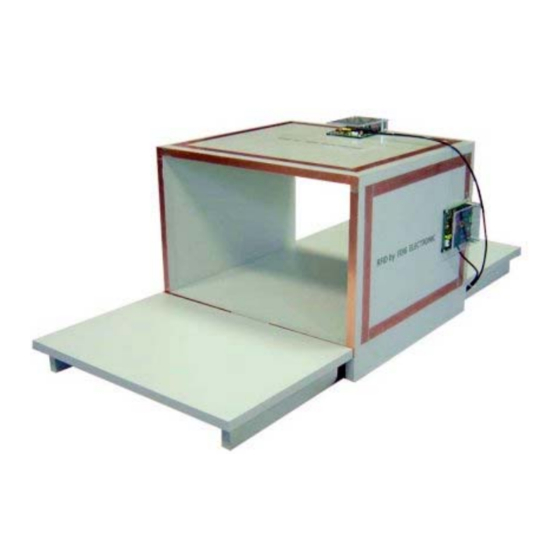
Page 6: Antennenaufbau: Tunnel Für Drei Ausrichtungen Der Transponder Mit Sechs Antennen
Transponder, benötigt, welche abwechselnd vom Multiplexer eingeschaltet werden. Hinweise: Zu beachten ist, dass der gesamte Erfassungsbereich des RFID-Tunnel größer ist als der skizzierte dreidimensionale Erfassungsbereich. D.h. es gibt Ausrichtungen in denen die Transponder außerhalb des gekennzeichneten Erfassungsbereich erkannt werden. FEIG ELECTRONIC GmbH Seite 6 von 54 N70101-2de-ID-B.doc... - Page 7 Werden mehrere Leser gleichzeitig im Abstand der Antennen von kleiner 8 m betrieben, so müssen die Reader synchronisiert werden. Siehe Application Note Das synchronisieren von RFID Long Range Readern über die digitalen Ein/Ausgänge (N11200-1d-ID-B.pdf). FEIG ELECTRONIC GmbH Seite 7 von 54 N70101-2de-ID-B.doc...
-
Page 8: Aufbau Und Einstellen Des Rfid-Tunnels
Kupferklebeband 5 – 25mm breit Ein geeignetes Gehäuse aus Kunststoff oder Holz an dem die Antennen und die Elektronik mon- tiert werden können. Keines Falls sollte das Gehäuse aus Metall oder größeren Metallteilen bestehen. FEIG ELECTRONIC GmbH Seite 8 von 54 N70101-2de-ID-B.doc... -
Page 9: Anschluss Des Antennenleiters
Bild 2) Bild 1 Bild 2 Bei Kupferrohr ist dieses an den Anschlusspunkten flach zu drücken und es sind geeignete Mon- tagelöcher zu bohren. Die Enden sind zu verzinnen.(siehe Bild 3) Bild 3 FEIG ELECTRONIC GmbH Seite 9 von 54 N70101-2de-ID-B.doc... - Page 10 Klemmschellen an die Abgleichplatine zu befestigen oder anzulöten. (siehe Bild 4) Bild 4 Bei Kupferklebeband sind die Übergänge und Ecken der einzelnen Leiterstreifen zu verlöten. (sie- Bild 5) Bild 5 FEIG ELECTRONIC GmbH Seite 10 von 54 N70101-2de-ID-B.doc...
- Page 11 Um eine phasengleiche Stromrichtung der beiden Antennenströme zu erhalten müssen die beiden Abgleichplatinen eines Gates, d.h. der gegenüberliegenden Antennen, um 180° zueinander ge- dreht montiert werden. (siehe Bild 6) Antenne 2 Antenne 1 oder Antenne 2 Antenne 1 Bild 6 FEIG ELECTRONIC GmbH Seite 11 von 54 N70101-2de-ID-B.doc...
-
Page 12: Benötigte Rfid Komponenten
® auf einem Personal Computer mit Microsoft Windows Betriebssystem benötigt. Die Service- ® software ist auf der OBID i-scan CD oder auf dem Download Bereich der Firma FEIG ELECTRONIC GmbH zu finden. FEIG ELECTRONIC GmbH Seite 12 von 54 N70101-2de-ID-B.doc... -
Page 13: Montage Und Anschluss
Das ideale Verhältnis der Seiten einer Antenne beträgt 1:1 (Quadrat). Das Verhältnis der Seiten einer Antenne sollte 3:5 (z.B. 300mmx500mm) nicht überschreiten. Die Antennenleiter von benachbarten Antennen sollten einen Mindestabstand von 2cm in alle Richtungen haben. (siehe Bild 8) FEIG ELECTRONIC GmbH Seite 13 von 54 N70101-2de-ID-B.doc... - Page 14 Die Lesereichweite der einzelnen Antenne sollte mindestens den halben Abstand der beiden zu- sammen eingeschalteten Antennen bei halber Sendeleistung des Lesers betragen. Die Antennenschleife hat immer nur eine Windung. (siehe Bild 9) Bild 9: Anzahl der Windungen der Antennenschleife FEIG ELECTRONIC GmbH Seite 14 von 54 N70101-2de-ID-B.doc...
-
Page 15: Verkabelung Des Rfid-Tunnels
Schleifen zusammengebunden werden. Dabei sind alle Kabel möglichst weit vom Antennenleiter weg zu binden. Die Kabel zwischen Antennenabgleich und Multiplexer sollten senkrecht vom An- tennenleiter weg geführt werden. Auf keinen Fall dürfen die Kabel den Antennenleiter berühren. FEIG ELECTRONIC GmbH Seite 15 von 54 N70101-2de-ID-B.doc... -
Page 16: Einstellung Des Power Splitters
Tabelle 1: Einstellung Power Splitter Trans- Power Phasen- former Splitter schieber not used Power Splitter X1: Reader X2: Antenne X3: Antenne X4: 12-24V DC bei Antenne mit dyn. Antennentuner ID ISC.DAT FEIG ELECTRONIC GmbH Seite 16 von 54 N70101-2de-ID-B.doc... -
Page 17: Einstellung Des Multiplexer
Darstellung eingestellt werden. Mehr zur Einstellung des Multiplexers ID ISC.ANT.MUX ist in der entsprechenden Montageanleitung (M30201-xde-ID-B) dokumentiert. Bild 11: Position DIP-Schalter und Jumper 3.1.3.1 Konfiguration des DIP-Schalter Der DIP- Schalter sollte laut folgender Tabelle konfiguriert werden: Tabelle 2: DIP- Schalter Konfiguration DIP- Schalter S1 FEIG ELECTRONIC GmbH Seite 17 von 54 N70101-2de-ID-B.doc... -
Page 18: Jumper Konfiguration
2Ω Gütewiderstand Antennenschalter Offen Die Jumper bzw. Lötbrücken JP11-14 und JP21-J26 sind offen. (Werkeinstellung) Die Einstellung ist zu überprüfen. Mehr zur Einstellung des Antennentuners ID ISC.DAT ist in der entsprechenden Montageanleitung (M40401-xde-ID-B) dokumentiert. FEIG ELECTRONIC GmbH Seite 18 von 54 N70101-2de-ID-B.doc... -
Page 19: Konfiguration Des Readers
Parameter wie folgt (ISO15693 Mode): • „Datacoding“ – 1 of 4 • „MOD“ – 10% • „SUB-CARRIER“ – ASK • „DATA-RATE“ – High • „NO-TS“ – 16 Timeslot • „AFI“ – Disabled FEIG ELECTRONIC GmbH Seite 19 von 54 N70101-2de-ID-B.doc... - Page 20 „Number of Input Channels“ – 2 Input (Dual Mode) • „MUX-Valid Time“ – 100 x 5 ms • „Number of Output Channels“ => 3 Durch „Write“ speichern Das Programm ISO Start schließen FEIG ELECTRONIC GmbH Seite 20 von 54 N70101-2de-ID-B.doc...
-
Page 21: Abgleichen Des Antennen
Antennen grün angezeigt. Rot angezeigte Antennen sind nicht abgeglichen. Falls dies nicht auf Anhieb gelingt, Abgleichvorgang mit „Start Tuning“ erneut starten Nach dem erfolgreichen Abgleichen ist die Software DATuningTool wieder zu schließen. FEIG ELECTRONIC GmbH Seite 21 von 54 N70101-2de-ID-B.doc... -
Page 22: Testen Des Rfid-Tunnels
Werden die Sollwerte nicht eingehalten, sind folgende Punkte zu überprüfen: • Sind alle Kabel fest angezogen und haben guten Kontakt ? • Wurden die Ringkerne in den Antennenkabel eingebaut ? • Wurden die Kabel vorschriftsmäßig verlegt ? FEIG ELECTRONIC GmbH Seite 22 von 54 N70101-2de-ID-B.doc... -
Page 23: Auslesen Einer Seriennummer
Gate 2 (Out 2+7) oder Gate 3 (Out 3+6) auswählen Mit „Send“ bestätigen “Test and Measurement” auswählen Funktion „ISO Inventory“ wählen und mit “Start” aktivieren. Die Seriennummer und der Transpondertyp werden im Display angezeigt. FEIG ELECTRONIC GmbH Seite 23 von 54 N70101-2de-ID-B.doc... -
Page 24: Aktivieren Des Buffered Read Mode
• Serial Number • Ant Store durch „Write“ speichern CFG12: Read Mode-Filter: VALID-TIME z.B. 600 x 100 ms durch „Write“ speichern CFG1: Interface and Mode „Buffered Read Mode“ auswählen. durch „Write“ speichern FEIG ELECTRONIC GmbH Seite 24 von 54 N70101-2de-ID-B.doc... -
Page 25: Testen Der Performance
LED am Reader ID ISC.LR2000 angezeigt wird. Anschließend ist das zulesende Objekt (z.B. Kiste) durch den endgültigen Aufbau des RFID- Tunnel zu bewegen. (siehe Bild 13) Bild 12 Bild 13 FEIG ELECTRONIC GmbH Seite 25 von 54 N70101-2de-ID-B.doc... -
Page 26: Starten Des Brm- Demo Programm
Programm mit „Start“ starten. Im „Protocol Window“ erscheinen die Sende- und Empfangsprotokolle Objekt (z.B. Kiste) mit Transpondern durch den RFID-Tunnel bewegen. Die gelesenen Transpon- der und die Anzahl werden aufgelistet. Hier 150 Stück FEIG ELECTRONIC GmbH Seite 26 von 54 N70101-2de-ID-B.doc... -
Page 27: Optimierung Der Lesegeschwindigkeit
Mit Advanced Quiet Funktion Standard ISO15693 Stay Quiet 0 m/s 1,2 s 2,8 s 0.5 m/s 1,2 s 2,1 s 0,75 m/s 1,2 s - s (nur 42 Stück gelesen) 1,0 m/s 1,2 s FEIG ELECTRONIC GmbH Seite 27 von 54 N70101-2de-ID-B.doc... -
Page 28: Advanced Quiet Funktion Im Leser Freischalten
Damit der Reader die Transponder spezifischen Kommandos ausführt müssen diese mit Hilfe ei- nes Freischaltcode freigeschaltet werden. Die Freischaltcode sind kostenpflichtig und müssen beim Customer Support der Firma FEIG ELECTRONIC GmbH angefordert werden (OBID-SUPPORT@FEIG.DE). FEIG ELECTRONIC GmbH Seite 28 von 54 N70101-2de-ID-B.doc... - Page 30 FEIG ELECTRONIC call explicit attention that devices which are subject of this document are not designed with components and testing methods for a level of reliability suitable for use in or in connection with surgical implants or as critical components in any life support systems whose failure to perform can reasonably be expected to cause significant injury to a human.
- Page 31 3.3.1 Testing the performance ....................51 Activating the BRM- Demo Programm ..............52 Optimization of the reading speed Reading speed with and without Advanced Quiet Function ........53 How to enable Advanced Quiet Function of the reader...........54 FEIG ELECTRONIC GmbH Page 31 of 54 N70101-2de-ID-B.doc...
- Page 32 Transponders. A multiplexer is switching between the antenna pairs (1-3 gates). Both antenna currents are in the phase generating a strong common magnetic field, which is capable of activating and reading small or a large numbers of Transponders. FEIG ELECTRONIC GmbH Page 32 of 54 N70101-2de-ID-B.doc...
-
Page 33: Antenna Setup: Tunnel For Three Orientations Of Transponders With Six Antennas33
If multiple RFID-Tunnel are arranged with short distances between each other, these will mutually interfere with each other. The Readers for the respective RFID-Tunnels must then be synchronized and if necessary be shielded. FEIG ELECTRONIC GmbH Page 33 of 54 N70101-2de-ID-B.doc... -
Page 34: Configuration And Setup Of The Rfid-Tunnel
Copper adhesive tape 5 – 25mm wide A suitable housing made of plastic or wood for fixing the antennas and the electronics. The housing should never be made of metal or contain large metal parts. FEIG ELECTRONIC GmbH Page 34 of 54 N70101-2de-ID-B.doc... -
Page 35: Connecting The Antenna Conductor
Copper pipe has to be pressed flat at the connecting points and the necessary mounting holes drilled. The pipe endings must coated in solder to prevent the oxidation of the contact area. (see Fig. 3) Fig. 3 FEIG ELECTRONIC GmbH Page 35 of 54 N70101-2de-ID-B.doc... - Page 36 At the use of copper adhesive tape the edges and overlapping ends have to be soldered (see Fig. 5). The overlapping areas of the copper tape must be minimized to limit parasitic capacitive effects. Fig. 5 FEIG ELECTRONIC GmbH Page 36 of 54 N70101-2de-ID-B.doc...
- Page 37 To ensure the currents of each antenna pair are in phase, one of the antenna boards of each gate has to be mounted 180º with respect to the other. (see Fig. 6) Antenna 1 Antenna 2 Antenna 2 Antenna 1 Fig. 6 FEIG ELECTRONIC GmbH Page 37 of 54 N70101-2de-ID-B.doc...
-
Page 38: Required Components
Microsoft Windows . The service software is included on ® the OBID i-scan CD obtained from FEIG ELECTRONIC GmbH or can be downloaded at the Download Area of the Homepage www.feig.de. FEIG ELECTRONIC GmbH Page 38 of 54 N70101-2de-ID-B.doc... -
Page 39: Mounting And Connecting
ID ISC.DAT antenna tuning board. • The best ratio of the sides of an antenna is 1:1 (square). • The ratio of the sides of an antenna shouldn’t exceed 3:5 (e.g. 300mmx500mm) FEIG ELECTRONIC GmbH Page 39 of 54 N70101-2de-ID-B.doc... - Page 40 The reading distance of one single antenna should be at least the half of the distance of the two connected antennas of a the gate, when the reader is configured to half output power. • The antenna loop has always one turn only. (see Fig. 9) Fig. 9 FEIG ELECTRONIC GmbH Page 40 of 54 N70101-2de-ID-B.doc...
-
Page 41: Configuration Of The Rfid-Tunnel
All cables have to be tied away from the antenna conductors as far as possible. The cables between antenna-tuning-board and multiplexer should be installed vertical away from the antenna conductor. In no case the cables should touch the antenna conductor. FEIG ELECTRONIC GmbH Page 41 of 54 N70101-2de-ID-B.doc... -
Page 42: Setting The Power Splitter
Table 1: Power Splitter setting Trans- Power Phase former Splitter shifter not used Power Splitter X1: Reader X2: Antenna X3: Antenna X4: 12-24V DC for Antenna with dyn. antenna tuner ID ISC.DAT FEIG ELECTRONIC GmbH Page 42 of 54 N70101-2de-ID-B.doc... -
Page 43: Setting The Multiplexer
ID ISC.ANT.MUX Multiplexer can be found in the corresponding installation manual (M30201-xde-ID-B). Fig. 11: DIP-Switch and Jumper positions 3.1.3.1 DIP Switch Configuration The DIP switch should be configured as indicated in the following table: Table 2: DIP switch configuration DIP-switch S1 FEIG ELECTRONIC GmbH Page 43 of 54 N70101-2de-ID-B.doc... -
Page 44: Jumper Configuration
Position open 1Ω Q resistor open 2Ω Q resistor Antenna switch open Verify these settings. More on setting the ID ISC.DAT antenna tuner can be found in the corresponding installation manual (M40401-xde-ID-B). FEIG ELECTRONIC GmbH Page 44 of 54 N70101-2de-ID-B.doc... -
Page 45: Reader Configuration
• „Datacoding“ – 1 of 4 • „MOD“ – 10% • „SUB-CARRIER“ – ASK • „DATA-RATE“ – High • „NO-TS“ – 16 Timeslot • „AFI“ – Disabled Set by clicking on “Write” FEIG ELECTRONIC GmbH Page 45 of 54 N70101-2de-ID-B.doc... - Page 46 • „Number of Input Channels“ – 2 Input • (Dual Mode) • „MUX-Valid Time“ – 200 x 5 ms • „Number of Output Channels“ => 3 Set by clicking on “Write” FEIG ELECTRONIC GmbH Page 46 of 54 N70101-2de-ID-B.doc...
-
Page 47: Tuning The Rfid-Tunnel
Red shown antennas are not tuned. If this does not succeed on the first try, start the process over again by clicking on „Start Tuning“ After successful tuning, close the DATuningTool again. FEIG ELECTRONIC GmbH Page 47 of 54 N70101-2de-ID-B.doc... -
Page 48: Testing The Rfid-Tunnel
Are all cables pulled tight and do they make good contact? • Were the ring cores installed in the antenna cable? • Were the cables routed as specified? • Are other RFID systems installed nearby? FEIG ELECTRONIC GmbH Page 48 of 54 N70101-2de-ID-B.doc... -
Page 49: Reading A Serial Number
Gate 3 (Out 3+6) Confirm with “Send” Select „Test and Measurement“ Select „ISO Inventory“ function and activate by clicking on „Start“. The serial number and tag type will be shown in the display. FEIG ELECTRONIC GmbH Page 49 of 54 N70101-2de-ID-B.doc... -
Page 50: Activating Buffered Read Mode
Set by clicking on “Write” CFG12: Read Mode-Filter VALID-TIME e.g. 600 x 100 ms Set by clicking on “Write” CFG1: Interface and Mode Select „Buffered Read Mode“. Set by clicking on “Write” FEIG ELECTRONIC GmbH Page 50 of 54 N70101-2de-ID-B.doc... -
Page 51: Testing The Performance
The tag must be read in the area of the antennas, which is indicated by a blue LED on the reader ID ISC.LR2000. (see Fig. 12) After that the object (e.g. box) can be moved through the final setup of the RFID-Tunnel. (see Fig. Fig. 12 Fig. 13 FEIG ELECTRONIC GmbH Page 51 of 54 N70101-2de-ID-B.doc... -
Page 52: Activating The Brm- Demo Programm
Start Program with „Start“ button In the „Protocol Window“ the Send- and Received Protocols are shown. Move Object (e.g. box) through the RFID-Tunnel The read tags and its quantity will be listed Here 150 pieces FEIG ELECTRONIC GmbH Page 52 of 54 N70101-2de-ID-B.doc... -
Page 53: Optimization Of The Reading Speed
With Advanced Quiet Function Standard ISO15693 Stay Quiet 0 m/s 1,2 s 2,8 s 0.5 m/s 1,2 s 2,1 s 0,75 m/s 1,2 s - s (just 42 pieces read) 1,0 m/s 1,2 s FEIG ELECTRONIC GmbH Page 53 of 54 N70101-2de-ID-B.doc... -
Page 54: How To Enable Advanced Quiet Function Of The Reader
If the reader should sent this special commands, this function has to be enabled with an activation code. This activation code is not free of charge and had to be ordered at the Customer Support of FEIG ELECTRONIC GmbH (OBID-SUPPORT@FEIG.DE). FEIG ELECTRONIC GmbH Page 54 of 54...
Need help?
Do you have a question about the OBID i-scan RFID-Tunnel and is the answer not in the manual?
Questions and answers