Table of Contents
Advertisement
Quick Links
Advertisement
Table of Contents

Related Manuals for LNS Alpha ST320 S2


Summary of Contents for LNS Alpha ST320 S2
- Page 1 Instruction manual LNS SA CH-2534 Orvin www.LNS-group.com 9.A02.01.ANG...
- Page 2 ALPHA ST320 S2...
-
Page 3: Table Of Contents
3. ELECTRICAL COMPONENTS 4-11 4. INTERFACE 4-18 4.1. Description 4-18 CHAPTER 5 PNEUMATICS 1. GENERAL DESCRIPTION 2. F.R.L. COMBINATION UNIT 3. SOLENOID VALVE MANIFOLD 4. MAINTENANCE CHAPTER 6 HYDRAULICS 1. GENERAL DESCRIPTION 2. DESCRIPTION OF THE ELEMENTS 3. MAINTENANCE ALPHA ST320 S2... - Page 4 1. BAR FEED SYSTEM ERROR MESSAGES 2. SERVO AMPLIFIER ERROR MESSAGES 9-17 3. FACTORS AFFECTING PERFORMANCE 9-23 4. MAINTENANCE 9-27 CHAPTER 10 APPENDICES 10-1 APPENDIX A: PROGRAMMING EXAMPLE 10-2 APPENDIX B: ORDERING FORM 10-3 APPENDIX C: ADRESS LNS 10-4 ALPHA ST320 S2...
-
Page 5: Chapter 1 Basic Notions
CHAPTER 1: BASIC NOTIONS CHAPTER 1 BASIC NOTIONS ALPHA ST320 S2... -
Page 6: Structure
(see chapter *) or (see point *). 1.2. Captions Whenever possible, the reference numbers contained in the instruction manual are shown with the LNS ordering number of the indicated element. To make it easier to place an order of supplies, a form has been included in the annex at the end of this manual. -
Page 7: Rights
LNS SA. LNS SA and its subsidiaries cannot be held responsible for damage and problems arising from the use of options and products other than LNS products, or products approved by LNS SA. -
Page 8: Safety Instructions
No servicing should be carried out on the it has been originally installed, do not reinstall interface or inside the electrical cabinet it before first contacting LNS or its local while the bar feeder or the lathe is under representative. -
Page 9: Safety Devices
4. SAFETY DEVICES 4.1. Description The ALPHA ST320 S2 bar feed system has been designed with a focus on maximum safety during its handling and complies with all EC requirements. Safety covers and devices make access to the moving parts of the bar feed system impossible. Safety switches keep the bar feed system from operating when these protections are open. - Page 10 CHAPTER 1: BASIC NOTIONS ALPHA ST320 S2...
-
Page 11: Chapter 2 Technical Data
CHAPTER 2: TECHNICAL DATA CHAPTER 2 TECHNICAL DATA ALPHA ST320 S2... -
Page 12: Characteristics (*)
6 - 20 6 - 22 The ALPHA ST320 S2 is able to load bar stock diameter from 3 up to 20 mm (22mm with bar stock preparation). For best performance, LNS strongly recommends to choose the channel diameter with a minimum space between the bar stock and the channel. - Page 13 CHAPTER 2: TECHNICAL DATA ALPHA ST320 S2...
-
Page 14: Layout Of The Elements
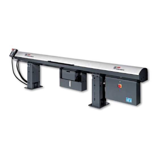
Front stand Rear stand Loading finger Air preparation unit (not visible) Electrical cabinet Pneumatic assembly Channel operation device (not visible) Front tube (for fixed head lathe) or telescope (for Swiss type lathe) Hydraulic pump Hydraulic oil tank ALPHA ST320 S2... - Page 15 CHAPTER 2: TECHNICAL DATA ALPHA ST320 S2...
-
Page 17: Chapter 3 Setting Into Operation
CHAPTER 3: SETTING INTO OPERATION CHAPTER 3 SETTING INTO OPERATION ALPHA ST320 S2... -
Page 18: Transportation
1. TRANSPORTATION 1.1. Description The Alpha ST320 S2 bar feed system may be delivered either on a pallet or packed in a wooden crate according to the customer requirement. The uncrating and lifting instructions recommended by LNS must be observed in order to prevent any injuries to persons and damaged to objects. - Page 19 CHAPTER 3: SETTING INTO OPERATION 1.3. Preparation of mounting For installing the bar feed system, it’s advisable to contact LNS or one of its branches, agents. The latter cannot be held responsible for any malfunction resulting from an incorrect installation in which they did not take part.
-
Page 20: Mounting
When the bar feed system finished FIRST FEED while the spindle is currently at maximum forward position, the bar stock front tip should keep 10mm gap from the rear end of the chuck. Material clamping Chuck / collet device Short pusher Bar stock length Guide bush ALPHA ST320 S2... - Page 21 B.2. Bar feeder system connected to Swiss type lathe: To get the shortest remnant, the pusher tip should be able to contact the rear end of the chuck when the spindle is currently at maximum forward position. Chuck / collet Guide bush ALPHA ST320 S2...
- Page 22 When the spindle is at maximum forward, distance L1 should be 10mm SMALLER than telescope’s maximum extended length. Guide bush When the spindle is at maximum backward, distance L2 should be 10mm LARGER than the telescope’s minimum retracted length. ALPHA ST320 S2...
-
Page 23: Alignment And Anchoring
Once the anchoring bolts are tightened, check the alignment again, and correct it if necessary. Tighten all the lock nuts (A). Notice: Before the bar feed system is anchored on the ground and the alignment is confirmed perfectly, the lock nuts (A) should not be tightened. ALPHA ST320 S2... - Page 24 At this stage, the hydraulic tank may be filled. • For the electrical connection, please see Chapter 4, Electrics. • For the pneumatic connection, please see Chapter 5, Pneumatics. • For filling the tank, please see Chapter 6, Hydraulics. ALPHA ST320 S2...
-
Page 25: Chapter 4 Electrics
CHAPTER 4: ELECTRICS CHAPTER 4 ELECTRICS ALPHA ST320 S2... -
Page 26: Electrical Equipment
Please read the safety instructions provided at the beginning of this manual before handling the following devices. Particular attention should be given to the handling of electrical elements because of risks of electrocution. In case of possible electrical malfunctions, it is advisable to contact LNS or their local representative. 1.1. Description The electrical parts of the bar feed system, as well as the diagrams representing them, conform to the ISO/IEC 204-1, 617 international electrical codes. - Page 27 Main switch Hydraulic pressure sensor Bar length measuring device Pusher in home position sensor Guide channel in closed position sensor Clamping device sensor Guide channel in open position sensor Main access cover closed sensor STP1 Emergency stop button ALPHA ST320 S2...
-
Page 28: Electrical Cabinet
K8 and KS: CE relay K8, K9, K10, KS K8,KS, K9 and K10 : double CE relay Electromagnetic switch Hydraulic pump (M2) contactor 24V DC power supply breaker Hydraulic pump (M2) breaker Servo amplifier 24V DC power supply Analogue module ALPHA ST320 S2... - Page 29 The power supplied to the bar feeder is protected by a breaker (6A max). 2.2.1. Main power switch QS1 Power OFF Power ON ON / OFF switch for the main power. Make sure it is turned OFF before opening the electrical cabinet. ALPHA ST320 S2...
- Page 30 The incoming power must be connected to the Primary Terminal Block. Use the contacts corresponding to the supplied power (346V AC to 440V AC, see drawing below). The outgoing power is always connected to the 220VAC terminals of the Secondary Terminal Block. Secondary terminal block Primary terminal block ALPHA ST320 S2...
- Page 31 SP1 / SQ0 SQ1 / SQ2 / SQ3 SQ4 Proximity switch / SQ5 Relay R1 ~ R5 Remote control buttons S1 ~ S7 Servo motor YV0 / YV1 Solenoid valve YV2A / YV2B YV3 / YV4 / YV5 ALPHA ST320 S2...
- Page 32 CHAPITRE 4: ELECTRICS 2.3.2. AC circuit ALPHA ST320 S2...
- Page 33 CHAPTER 4: ELECTRICS 2.3.3. Emergency stop loop ALPHA ST320 S2...
- Page 34 4-10 CHAPITRE 4: ELECTRICS ALPHA ST320 S2...
-
Page 35: Electrical Components
Never change the parameter settings of the Servo Amplifier. They are factory pre-set. Designation Description I/O connector Encoder connector Serial connector 2 phases 220 V input for controller 3 phases 220 V input 3 phases 220 V output for motor Protective earth Display ALPHA ST320 S2... - Page 36 Y14. When this signal is OFF, the KM1 is de- energized and the power to hydraulic pump is cut off. Designation Description Power poles input (from QM1) Control circuit Status indicator Power poles output (to M2) ALPHA ST320 S2...
- Page 37 4A, the breaker activates and lever B flips down. The power supply to PLC and 24V DC power supply is immediately interrupted. After the problem is fixed, reset the breaker by flipping lever B Designation Description Power poles input ON / OFF lever Power poles output ALPHA ST320 S2...
- Page 38 Input contacts notation Input signals indication LED. Indicates the status of inputs X0 to X43 PLC status indication LED Communication port Output signals indication LED. Indicate the status of outputs Y0 to Y27 Output contacts notation Output contacts ALPHA ST320 S2...
- Page 39 CHAPTER 4: ELECTRICS 4-15 b) Analogue module The analogue signals are used to control the torque and speed of the servo motor. Designation Description Torque control output contacts Speed control output contacts Power indication LED ALPHA ST320 S2...
- Page 40 4-16 CHAPITRE 4: ELECTRICS c) I/O diagram ALPHA ST320 S2...
- Page 41 PCB is a board with circuit printed and electrical components welded on the surface. It offers sockets and terminals for electrical components like relays, cables and fuses. Refer to the table below for functions of each terminal. ALPHA ST320 S2...
-
Page 42: Interface
Before connecting the bar feeder, make sure the installed interface is suitable for your lathe. If in doubt – contact LNS. A correct connection between lathe and bar feeder is critical for safe and reliable operation. - Page 43 CHAPTER 4: ELECTRICS 4-19 4.2. Interface diagram example ALPHA ST320 S2...
- Page 44 MODE 5 setup.) After the last part is machined, the stopper is usually not present anymore. The bar feed system must not push the bar when the chuck is open. To avoid this, the TORQUE STOP signal must be ON. ALPHA ST320 S2...
- Page 45 For lathes that the spindle is not allowed to rotate when chuck is open, this signal acts as an external order to turn the spindle. Refer to service parameter MODE 25 for more information. ALPHA ST320 S2...
- Page 46 CHAPITRE 4: ELECTRICS 4.5. Options The options described below are an integral part of the standard equipment of the LNS SA bar feed system. These signals, however, are not required for the proper operation of the device or the safety locking for protecting persons and materials.
-
Page 47: Chapter 5 Pneumatics
CHAPTER 5: PNEUMATICS CHAPTER 5 PNEUMATICS ALPHA ST320 S2... -
Page 48: General Description
CHAPTER 5: PNEUMATICS 1. GENERAL DESCRIPTION 1.1. Description The following automatic movements of the ALPHA ST320 S2 bar feed system are done via pneumatic elements, namely: • Loading finger • Channel opening/closing pneumatic cylinder • Material clamping device • Bar length measuring device •... -
Page 49: Combination Unit
The air must be furnished at a pressure of 5 bar and whenever possible, clean and dry. 2.2. Layout of the elements Description Air inlet Pressure regulator Pressure gauge Condensate collector Lubricator Oil cup Regulated air outlet with 8mm / G1/4 push-in fitting Oil refilling plug ALPHA ST320 S2... - Page 50 CHAPTER 5: PNEUMATICS 2.3. Connection For the pneumatic connections of the bar feed system, LNS SA provides a tube with quick acting coupler and probe pre-mounted. Before connection, confirm the factory air pressure is not larger then 8 bar / 14 psi. Connect this tube on both F.R.L.
-
Page 51: Solenoid Valve Manifold
Ø8mm air inlet (from F.R.L. combination) C14120200 Air outlet / silencers C11120400 Pressure switch (PE converter) C1110100 Spindle attached anti-vibration (optional) C13110401 Air blast C1110100 Material clamping device C1110100 Front rest C1110100 Material loading YV2A / C1110200 Channel opening / closing YV2B ALPHA ST320 S2... - Page 52 The pressure switch engages when the pressure is larger than 2 bar and closes the emergency stop circuit. When the air pressure drops below 0.5 bar, the switch disengages and interrupts the emergency stop circuit. An alarm e01 arises. ALPHA ST320 S2...
-
Page 53: Maintenance
For the best performance, the oil should drop every cylinder operation. Adjust the fluent with auxiliary of channel open button. Let the oil drop once after pressing the “channel open” button for 10 times. • Connect the air inlet tube and turn air source on. ALPHA ST320 S2... - Page 54 CHAPTER 5: PNEUMATICS ALPHA ST320 S2...
-
Page 55: Chapter 6 Hydraulics
CHAPTER 6: HYDRAULICS CHAPTER 6 HYDRAULICS ALPHA ST320 S2... -
Page 56: General Description
CHAPTER 6: HYDRAULICS 1. GENERAL DESCRIPTION The guiding concept of the ALPHA ST320 S2 feed system consists mainly in maintaining the bar suspended in an oil bath. The hydraulic pump injects the oil into the space between running bar stock and guiding channel elements hence achieve functions below: 1. -
Page 57: Description Of The Elements
The remnants might be lying between the material clamping space and interrupt the next bar stock insertion. The tray might be too heavy to be moved. It is recommended to keep the height of the remnant hip under the opening. Under the opening. ALPHA ST320 S2... -
Page 58: Maintenance
Refill new oil into the bar feed system until the indicator shows oil level at H (about 25 litres needed). Confirm there is no leaking from the plug. • Install the remnant tray back. Dispose of waste used oil properly in an environmentally friendly way, and according to your local regulation. ALPHA ST320 S2... -
Page 59: Chapter 7 General Description
CHAPTER 7: GENERAL DESCRIPTION CHAPTER 7 GENERAL DESCRIPTION ALPHA ST320 S2... -
Page 60: Loading System
1.2. Layout of the elements Designation Description Bar guiding limiter adjusting knob Loading finger Locking system Dial Loading cylinder ALPHA ST320 S2... - Page 61 3 to 7mm, section B allows bar diameter ranging from 7 to 12mm, and section C allows bar diameter ranging from 12 to 20mm. Release the adjustment knob, move the guiding limiter to the section according to bar diameter, then lock it in its new location. ALPHA ST320 S2...
-
Page 62: Channel Set Part I: Guiding System
Sets of guiding channel of different dimensions are available. Each dimension of guiding channel is available to load a range of bar stock dimensions. For a best performance of guiding, it is recommended to keep the gap width between bar stock and channel around 1mm. ALPHA ST320 S2... - Page 63 Whenever the channel replacement is needed, check chapter 7.4 for further information. 2.2. Layout of the elements Designation Description Movable channel cover Fixed guiding channel Oil injection tube Front tube (for Fixed type lathe) or Telescope (for Swiss type lathe) ALPHA ST320 S2...
-
Page 64: Channel Set Part Ii: Feeding System
Part of the long pusher is able to extend out side the bar feed system. In the other hand, the pusher must enter the spindle to get a shortest remnant. During installation, it must be confirmed that the tip of long pusher is able to contact the rear end of lathe chuck. ALPHA ST320 S2... - Page 65 Each finger chuck matches a specific bar stock dimension only. For profiled bar stock, the finger chuck diameter must be selected according to the virtual circle created by the bar stock corners. Refer to annex table for dimension conversion. ALPHA ST320 S2...
- Page 66 Position A: Slightly loose the screws. Manually move the chain wheel backward (toward the motor) and lock the screws. 2. Move the motor and wheel set away from the lathe and tighten again. 1. Loose the screws ALPHA ST320 S2...
- Page 67 Depends on the diameter of bar stocks, the finger component must be replaced accordingly. • When the pusher is at home position. Open the guiding channel. • Replace the finger chuck / rotating joint. Rotating sleeve Finger chuck ALPHA ST320 S2...
-
Page 68: Channel Set Changeover Procedure
Install short pusher and long pusher (with rotating joint). • Mount the pusher carriers. • Reset the emergency stop button. Move pusher to position 1400 and close the channel cover. • Move the pusher to home position. ALPHA ST320 S2... - Page 69 STT21-length XT193062100 XHP08-37-2-E1 STT08-length XT193060800 XHP11-37-2-E1 STT11-length XT193061100 XHP14-37-2-E1 STT14-length XT193061400 LtoR/F XHP17-37-2-E1 STT17-length XT193061700 XHP19-37-2-E1 STT19-length XT193061900 XHP21-37-2-E1 STT21-length XT193062100 1) Length: The front tube length. Four lengths are available: 120, 260, 310 and 400 mm. ALPHA ST320 S2...
- Page 70 XTP21-20-37-E1 and STT21-260 • Example2: If the user wants to change the current channel from someone to 17. The bar feed system is 3m and the lathe is Swiss type. He has to order: XTP17-16-32-E1 and XT193061700. ALPHA ST320 S2...
-
Page 71: Material Clamping Device
5.3. Replacement of the blades The clamping blades must be replaced when worn out. Proceed the procedures below : Unscrew the screws (A) the removed the worn blades (B). Install the new blades and tighten with the removed screw. ALPHA ST320 S2... -
Page 72: Front Rest Devices
One standard front rest device is mounted on front of the bar feed system. For Swiss type lathe, an optional spindle attached front rest is available and offered by request. 6.2. Layout of the elements Designation Description Blower Clamping adjustment Releasing adjustment Scale ALPHA ST320 S2... - Page 73 For profiled bar stocks, specific guiding elements machined at the correct diameter are available. Standard V element Round element for profiled bar stocks ALPHA ST320 S2...
-
Page 74: Bar Length Measuring Device
Since the bar length measuring sensor is only activated by the bar tip, please note that the TOP CUT distance is independent from the bar stock length. Once the bar feeder position is fixed, the TOP CUT position is only related to the distance from the bar feeder to the lathe chuck surface. Flap ALPHA ST320 S2... -
Page 75: Air Blast Ring
While the bar feeder is doing FIRST FEED. Designation Description Air blast ring Set collar Insert into bar feeder Front tube / telescope from this side. The ring must be mounted during installation. Refer to figure below for correct installation direction. ALPHA ST320 S2... -
Page 76: Lathe Connecting Parts (Option)
Front tube or telescope (optional) The connecting parts design varies with the lathe type and brand. Diagram of connecting parts shipped with the bar feeder was placed inside the accessories box. Refer to the diagram to do the installation. ALPHA ST320 S2... -
Page 77: Bar Preparation
To maximize the bar stock diameter, the user is recommended to turn down the bar tip as shown. The maximum bar stock diameter should be kept 1mm below the guiding channel. ALPHA ST320 S2... - Page 78 7-20 CHAPTER 7: GENERAL DESCRIPTION ALPHA ST320 S2...
-
Page 79: Chapter 8 Operation
CHAPTER 8: OPERATION CHAPTER 8 OPERATION ALPHA ST320 S2... -
Page 80: Controls
There is a communication failure between the PLC and the HMI. Middle-green light The RS-232 interface is not used and the LED remains OFF. Bottom-Green light The RS-485 LED indicates communication activity between the PLC and HMI ALPHA ST320 S2... - Page 81 MANUAL mode, the key LED is ON and the user could operate the bar by function keys. • Reset the bar feed system from an emergency stop. Rightward Move pusher rightward. Only available when the bar feed system is in MANUAL mode. ALPHA ST320 S2...
- Page 82 • Channel close and the pusher charges forward for insertion. To operate this button, the following conditions must be fulfilled: • The bar feed system is in MANUAL mode • The pusher is at home position (sensor SQ2 ON) ALPHA ST320 S2...
-
Page 83: Onboard Hmi (Human-Machine Interface)
: To access the SERVICE PARAMETER screen. Refer to Chapter 8.6. : To display the software version. Both HMI and PLC has their own software as shown. This information is sometimes necessary when you contact us for technical support. ALPHA ST320 S2... - Page 84 Powering up the bar feeder. After initialization of the HMI the LED will turn OFF. There is a communication failure between the PLC and the HMI. RS-485 (green) The RS-485 LED indicates communication activity between the PLC and HMI. The RS-232 interface is not used and the LED remains OFF. ALPHA ST320 S2...
-
Page 85: Powering
CHAPTER 8: OPERATION 3. POWERING The motor of the ALPHA ST320 S2 bar feed system is equipped with a built-in absolute encoder that continuously controls the position of the carrier. When the bar feed system is powered down or there is a power failure, this position is kept in the memory by the PLC. -
Page 86: Emergency Stop Button
An alarm e01 is arising at HMI. When the emergency situation is fixed, release the emergency stop button and press the manual key on the remote control to restart the bar feed system. Emergency stop button on the remote control STP1 INTERRUPTION RESET ALPHA ST320 S2... -
Page 87: Automatic Sequence
CHAPTER 8: OPERATION 5. AUTOMATIC SEQUENCE The ALPHA ST320 S2 bar feed system could be switched into AUTOMATIC mode at two timings. 5.1. Starting a new machining Warning: Conditions must be fulfilled: 1. The lathe is not in AUTOMATIC mode. -
Page 88: Operation Parameters
Press F0 for the 1 parameter displayed • Press F1 for the 2 parameter displayed • Press F2 for the 3 parameter displayed Validation of the changes: After editing the value you must press the key to confirm the new setting. ALPHA ST320 S2... - Page 89 Maximum allowable feeding length when chuck is open. FIRST FEED FIRST FEED position Chuck open timer Timer for chuck open Dry run Barfeeder in dry run mode Front rest in manual Front rest in manual mode mode ALPHA ST320 S2...
- Page 90 The distance where the pusher reduces it’s feeding speed prior to arrive at part length set above during feeding. The purpose is to prevent the impact between bar stock and stopper. Note: This setup only applied on general feeding but not TOP CUT feeding. ALPHA ST320 S2...
- Page 91 “Position” on the display by 10 as BAR END position. • When pusher arrives this position during AUTOMATIC mode, the bar feed system sends a BAR END signal to the lathe and proceeds the bar change process accordingly. ALPHA ST320 S2...
- Page 92 The current pusher position measured from home position SQ2. 1st : The pusher position where the first front rest opens. 2nd : The pusher position where the hydraulic pump turns OFF. Option : The pusher position where the second front rest (optional) opens. ALPHA ST320 S2...
- Page 93 The pusher moves forward to position P08 “extract position” + 100mm to push the remnant in the remnant box. The pusher go back to P08 “extract position” and the clamping device closes again to verify absence of remnant. ALPHA ST320 S2...
- Page 94 OFF when the installation is accomplished. P11: Manual mode of the front rest Current position : (read only) The current pusher position measured from sensor SQ2. Manual Mode : If this function is activated, Front rest operates in manual mode. ALPHA ST320 S2...
-
Page 95: Services Parameters
Accessing these parameters is password protected. Please contact LNS or its official agent in your country for getting technical support in case any modification is needed. - Page 96 The pushing signal allows the lathe to control the pushing force during machining operations. 0 – Pushing signal (A4) prohibits pusher forward actions during machining (If the lathe don’t provide A4, mode 5=0) 1 – Pushing signal (A4) allows pusher forward actions during machining ALPHA ST320 S2...
- Page 97 0 – The remnant is retracted inside the bar feed system with auxiliary of material clamping device. 1 – The remnant is ejected into the lathe by new bar stock. Note: The pusher finger chuck should be replaced by push type accordingly. ALPHA ST320 S2...
- Page 98 1 – The pusher terminates pushing force. : : : : MODE 13 Synchronization device (optional) setup 1 of 2 (refer to MODE 29 for related setup) 0 – Activate synchronization device. 1 – Deactivate synchronization device. ALPHA ST320 S2...
- Page 99 Signals sent under this condition are called CYCLE START signal. 1 – Y05 starts to be ON when a new bar stock arrives at TOP CUT position and OFF when the next loading cycle initiated. Signal sent under this condition is called WORKING signal. ALPHA ST320 S2...
- Page 100 This setup only validates when MODE 6 set 1. Note: Before the bar change cycle initiated, MODE 12 or TORQUE STOP (A4) signal decides if pushing force applied on pusher. ALPHA ST320 S2...
- Page 101 Lathe type setup 3 of 3 (refer to MODE 21, 22 for related setup) 0 – For the lathes whose brand name are not “EASY”. 1 – For the lathes whose brand name are “EASY” only. : : : : MODE 23 HMI display language setup 0 – Optional language ALPHA ST320 S2...
- Page 102 This parameter defines if the pusher movement activated. The INCHING signal is not affected. 0 – Activate pusher movement. 1 – Deactivate pusher movement. ALPHA ST320 S2...
- Page 103 0 – The bar feed system holds this signal right after receive it either the it’s continuous or a pulse until new bar stock arrives TOP CUT position 1 – The bar feed system read and apply the signal as how it sent from the lathe. ALPHA ST320 S2...
- Page 104 If the lathe does not provides A7, MODE 30=0 : : : : MODE 31 Length check skip Define the number of check processes for the feeding length that will be skipped after a new bar stock was loaded. Possible values are 1 to 5. ALPHA ST320 S2...
- Page 105 P02 (part length) + 50mm. P07 <= (P02 + 50) 1 – P07 (too long distance) has no limit. In some applications P07 must be set bigger than (P02 + 50). MODE 35 This parameter originally is left blank. ALPHA ST320 S2...
-
Page 107: Chapter 9 Troubleshooting
CHAPTER 9: TROUBLESHOOTING CHAPTER 9 TROUBLESHOOTING ALPHA ST320 S2... -
Page 108: Bar Feed System Error Messages
Whenever an error message activated, please follow the description and trouble shooting to check the problem. If necessary, contact LNS for technical support. 1. BAR FEED SYSTEM ERROR MESSAGES 1.1. - Page 109 If MODE 26=0, proceeds step If MODE 26=1, p roceeds step If this step cannot be accomplished in Pusher moves 100mm forward 5 seconds. and returns. If this step cannot be accomplished in Material clamping device 4 seconds. clamps and releases. ALPHA ST320 S2...
- Page 110 START signal e28 If the pusher’s backward moving Spindle distance is larger than <too short moves dist> on P07. backward part length. e13 Check chapter 9.1.2 for further Close chuck and proceed to information. step 28. ALPHA ST320 S2...
- Page 111 (input signal of relay R1). The alarm e01 is arising at HMI. Check the circuit step by step to locate the broke point. Reset the component or contact LNS for technical support. Trouble shooting Check if the emergency stop button on electrical cabinet was pressed.
- Page 112 2.1. Check if there is something blocking the cover or the cover is bent therefore the sensor SQ8 is not energized. 2.2. Check if the switch SQ8 is broken. If it is, please replace the switch or contact LNS for technical support. e03 Servo alarm Meaning An alarm is activated at the servo amplifier.
- Page 113 2. Check if the sensor SQ4 is broken. e08 NC alarm Meaning An alarm is activated on the lathe. Explanation Relay A2 is energized by the interface signal. Trouble shooting Check the lathe alarm detail and follow the trouble shooting guide to solve it. ALPHA ST320 S2...
- Page 114 ON/OFF 3 cycles. Note: The error is checking the chuck signal only. It’s not about if the lathe is in AUTOMATIC mode or not. Trouble shooting Switch the bar feed system into AUTOMATIC mode if it supposed to be. ALPHA ST320 S2...
- Page 115 6. Check if <too short dist> setup on P07 is incorrect. 7. Check if the timer for controlling the chuck open/close is too short. 8. Check if the stopper position is incorrect. 9. Check if BAR END setup is incorrect. ALPHA ST320 S2...
- Page 116 2. Check if the bar stock was pre-treated with proper bar preparation (please refer to chapter 7.10). 3. Check if the remnant if full. 4. Check if the material clamping device blades are worn out or broken. 5. Check if the air pressure is too low. ALPHA ST320 S2...
- Page 117 Check step 2 and 17 on chapter 9.1.1 for further information. Trouble shooting 1. Check if the channel or lathe spindle blocked. 2. Check if the transmission mechanism is broken. 3. Check if the origin reference sensor SQ2 is broken. ALPHA ST320 S2...
- Page 118 Trouble shooting 1. Check if the lathe receives START signal from the bar feed system. 2. Check if the bar feed system receives CHUCK signal. 3. Check if the interface cable connection status is functioning. ALPHA ST320 S2...
- Page 119 3. Check if <too short dist_*> setup on P07 is incorrect. 4. Check if BAR END setup is incorrect. 5. Check if the synchronization device works correctly (if it’s equipped and activated). ALPHA ST320 S2...
- Page 120 1. Check if the bar stock is escaping from the chuck 2. Check if <too long dist_*> setup on P07 is incorrect. 3. Check if the transmission mechanism is broken. 4. Check if the chuck is broken or the pressure setup is incorrect. ALPHA ST320 S2...
- Page 121 The TOP CUT position setup or the stopper position is incorrect. Explanation The pusher is not stopped within 50mm beyond the TOP CUT position. (only available when MODE 8 = 0) Trouble shooting 1. Check <TOP CUT> setup on parameter P05. 2. Check the stopper position. ALPHA ST320 S2...
- Page 122 Trouble shooting Check the actual pusher movement e30 Dry Run error Signification The barfeeder is in Dry Run mode Explication • Impossible movement, barfeeder in Dry Run mode Trooble shooting Skip the barfeeder in automatic or manual mode. ALPHA ST320 S2...
-
Page 123: Servo Amplifier Error Messages
Reconfirm power switch. circuit. input voltage at main circuit is normal. Input power error. (Incorrect Use voltmeter to check whether Use correct power supply or power input) the input voltage is within the serial stabilizing power. specified limit. ALPHA ST320 S2... - Page 124 (too much fluctuation). input signal is abnormal. frequency stable (not fluctuate much) activate filter function (P1-06, P1-07 and P1-08). Over-speed parameter setting Check if over-speed parameter Correctly over-speed is defective. setting value is too low. parameter setting (P2-34). ALPHA ST320 S2...
- Page 125 Encoder is loose. Examine encoder Install the motor again. connector. The wiring of encoder Check if all connections are Conduct the wiring again. defective. tight. Encoder is damage. Check the encoder for the Repair or replace the motor. damage. ALPHA ST320 S2...
- Page 126 Check if there is overload or Increase motor capacity or rated load during continuous the motor current is too high. reduce load. operation. Short-circuit at drive output. Check the drive input wiring. Ensure all wiring is correct. ALPHA ST320 S2...
- Page 127 Potential Cause Checking Method Corrective Actions Control power is in error. Check and reset control power If the error does not clear after resetting the power supply, please contact your distributor for assistance or contact with Delta. ALPHA ST320 S2...
- Page 128 ALE06. 2. Check the setting value of 2. Increase the setting value of P1-56. Check whether the P1-56 or set P1-56 to 100 setting value of P1-56 is too and above. small. ALPHA ST320 S2...
-
Page 129: Factors Affecting Performance
It is, therefore, highly recommended to install reduction liner inside the spindle. Please contact your LNS SA dealer for further information. - Page 130 In general, the difficulty increases with the specific weight of the bar. Steel bars are relatively easy to guide. Because of their great flexibility and specific weight, brass bars are relatively difficult to guide at high speeds. Aluminium bars of aluminium are very easy to guide. ALPHA ST320 S2...
- Page 131 Double cone collet The double cone clamp has the great advantage of holding the bar at two points separated by about 1.5 the diameter, with a clamping 2 times 350 degrees over about 0.5 times the diameter. Efficiency: excellent ALPHA ST320 S2...
- Page 132 The radius of the jaws is greater than the radius of the bar. The jaws press against only three points at 120 degrees. 60° Correct: Modify the centers of the jaws to obtain 2 times 6 support clamping points at 60 degrees. ALPHA ST320 S2...
-
Page 133: Maintenance
At no time should solvents, such as acetone, or diluents be used for cleaning the bar feed system. At no time should cleaning products come into contact with electrical components. ALPHA ST320 S2... - Page 134 9-28 CHAPTER 9: TROUBLESHOOTING ALPHA ST320 S2...
-
Page 135: Chapter 10 Appendices
APPENDICES 10-1 CHAPTER 10 APPENDICES ALPHA ST320 S2... -
Page 136: Appendix A: Programming Example
N... N... X, Z, G, F, T, S, M, ... N... N... END OF PROGRAM (LOOP) Important: The above is an example only. Programming may change according to the interface between the lathe and the bar feed. ALPHA ST320 S2... -
Page 137: Appendix B: Ordering Form
APPENDICES 10-3 APPENDIX B: ORDERING FORM This form should be photocopied, duly filled out, and returned to your retailer or nearest LNS agent Company name: Person in charge: Address: ZIP: City: Country: Phone: Fax: Type of device: Serial number: Qty. -
Page 138: Appendix C: Adress Lns
21053 Castellanza – VA Tel : +39 0 331 501 901 Fax : +39 0 331 482 101 TÜRKİYE LNS Makine San.Tic.A.Ş.Via Mons. Colombo 34 info-turkiye@LNS-europe.com Keresteciler San.Sit. 10.Sk.No:45 www.Lns-europe.com Kazan - Ankara / TÜRKİYE Tel : +90 312 815 24 34...
Need help?
Do you have a question about the Alpha ST320 S2 and is the answer not in the manual?
Questions and answers
What is the commodity code for a LNS Alpha ST320 S2 Bar Feed?