Advertisement
Quick Links
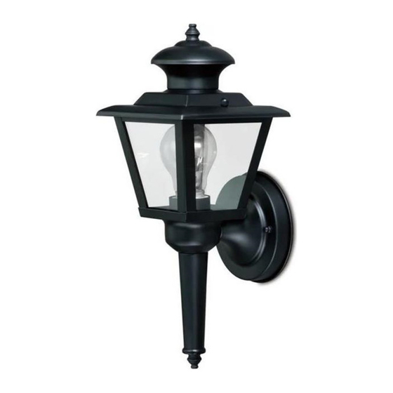
ASSEMBLY AND INSTALLATION
T0429 / T0430
WARNING:
NOTES: 1. Before installing, consult local electrical codes for wiring and grounding requirements.
2. Read and save these instructions.
Important to Know
1. Read all instructions carefully before installation and operation.
2. If you are not familiar with state and local electrical codes, it is recommended that you consult with a qualified
electrician.
3. Before installation, shut off power at the main fuse or circuit breaker box. Be aware that simply turning off the
wall switch is not sufficient to prevent an electrical shock.
4. This fixture requires a 120 VAC, 60 Hz power source.
5. Do not attempt to take the lantern apart; there are no serviceable parts inside.
Maximum Wattage: 60W Incandescent Bulb
Work Temperature: - 4°F~104°F
HARDWARE CONTENTS Note: Hardware not shown actual size.
AA
BB
CC
DD
INSTRUCTIONS
TO AVOID RISK OF ELECTRICAL SHOCK, BE SURE TO SHUT OFF
POWER BEFORE INSTALLING OR SERVICING THIS FIXTURE.
Cross Bar
X1
Mounting Screw
X2
Headless Screw
X2
Wire Connector
X3
Page 1 of 3
Lock Nut
EE
X4
Ball Nut
FF
X2
Rubber Pad
GG
X2
Green Grounding
HH
Screw X1
180806
Advertisement

Related Manuals for Vaxcel Proline T0429


Summary of Contents for Vaxcel Proline T0429
- Page 1 ASSEMBLY AND INSTALLATION INSTRUCTIONS T0429 / T0430 WARNING: TO AVOID RISK OF ELECTRICAL SHOCK, BE SURE TO SHUT OFF POWER BEFORE INSTALLING OR SERVICING THIS FIXTURE. NOTES: 1. Before installing, consult local electrical codes for wiring and grounding requirements. 2. Read and save these instructions. Important to Know 1.
- Page 2 SAFETY INFORMATION Please read and understand this entire manual before attempting to assemble, operate or install the product. WARNING ● Turn off electricity at main fuse box (or circuit breaker box) before beginning installation by removing fuse (or switching off circuit breaker). ●...
- Page 3 ASSEMBLY INSTRUCTIONS (continued) 7. Unscrew the set screws and 5. Attach the back plate to the set screw rubber pads form fixture.Attach cross bar by inserting the Rubber Pad the cover to the main fixture by headless screws (CC), then Cover aligning holes, secure it with two secure it with rubber pads...
Need help?
Do you have a question about the Proline T0429 and is the answer not in the manual?
Questions and answers