Advertisement
Quick Links
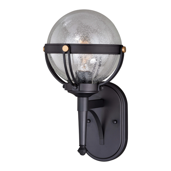
ASSEMBLY AND INSTALLATION
T0451 / T0455
WARNING:
NOTES: 1. Before installing, consult local electrical codes for wiring and grounding requirements.
2. READ AND SAVE THESE INSTRUCTIONS.
Hardware Package (included):
Mounting Screw (B)
Cross Bar (A)
Installation Steps
Turn off the power at fuse or circuit box
1. Thread two headless screws (D) through the cross bar (A), and then secure
them with four lock nuts (E). Adjust the length of the headless screws (D)
if necessary.
Note: Make sure that the headless screws are lined up horizontally to
make the fixture level.
2. Attach the cross bar (A) to the outlet box by using two mounting screws (B).
3. Pull out the source wires from the outlet box. Make wire connections using
wire connectors (F) as follows:
---Connect the hot wire (usually black insulation) from the fixture to the black
wire from the power source.
---Connect the neutral wire (usually white insulation) from the fixture to the
white wire from the power source.
---Attach the fixture grounding wire (usually green insulation or bare wire) to
the cross bar with the green grounding screw (C), and then connect it to
the house grounding wire with the wire connector (F).
Carefully put the wires back into the outlet box.
Wire Connector (F)
Headless Screw (D)
Fixture Grounding Wire
Green Grounding Screw (C)
Mounting Screw (B)
INSTRUCTIONS
TO AVOID RISK OF ELECTRICAL SHOCK, BE SURE TO SHUT OFF
POWER BEFORE INSTALLING OR SERVICING THIS FIXTURE.
Green Grounding
Headless Screw (D)
Screw (C)
Outlet Box
Cross Bar (A)
Lock Nut (E)
Wire Connector (F)
Fixture
Back Plate
Ball Nut (G) Rubber Pad (H)
Glass
Bulb Type A
Max. 60W
(not included)
Replacement Ball Nut
Ball Nut (G)
Rubber Pad (H)
181029
Advertisement

Subscribe to Our Youtube Channel
Related Manuals for Vaxcel T0451


Summary of Contents for Vaxcel T0451
- Page 1 ASSEMBLY AND INSTALLATION INSTRUCTIONS T0451 / T0455 WARNING: TO AVOID RISK OF ELECTRICAL SHOCK, BE SURE TO SHUT OFF POWER BEFORE INSTALLING OR SERVICING THIS FIXTURE. NOTES: 1. Before installing, consult local electrical codes for wiring and grounding requirements. 2. READ AND SAVE THESE INSTRUCTIONS.
- Page 2 Spare Parts List: Assembly Kit 6001MM (1SET) Mounting Screw (B) Cross Bar (A) Green Grounding Screw (C) Headless Screw (D) Glass T0451 10036CS T0455 10037CS Ball Nut (G) Rubber Pad (H) Wire Connector (F) T0451 T0455 A: 8” A: 9-3/4”...
Need help?
Do you have a question about the T0451 and is the answer not in the manual?
Questions and answers