Advertisement
Quick Links
ASSEMBLY AND INSTALLATION
T0468
WARNING:
NOTES: 1. Before installing, consult local electrical codes for wiring and grounding requirements.
2. READ AND SAVE THESE INSTRUCTIONS.
Hardware Package (included):
Mounting plate (A)
Green Grounding
Screw (E)
Outlet Box
House Grounding Wire
Green Grounding Screw (E)
Mounting Plate (A)
Mounting Screw (B)
Headless Screw (D)
Lock Nut (F)
Fixture Grounding Wire
IMPORTANT:
The sensor has an excellent photocell function
to enable the light to turn on at dusk and off at
dawn automatically.
Turn off the power at fuse or circuit box
1. Thread two headless screws (D) through the mounting
plate (A), then secure them with four lock nuts (F) (two
on each side of the mounting plate). Adjust the length
of the headless screws (D) if necessary.
Note: Make sure that the headless screws (D) are lined up
horizontally, to ensure that the fixture will be level.
2. Attach the mounting plate (A) to the outlet box by using two
mounting screws (B).
3. Take a glass panel and gentle slide it into the glass frame
in place, secure it by pressing two clips on top side of the
glass frame and two clips on the bottom of the glass frame.
Repeat with the other glass panels. (See Fig.1)
INSTRUCTIONS
TO AVOID RISK OF ELECTRICAL SHOCK, BE SURE TO SHUT OFF
POWER BEFORE INSTALLING OR SERVICING THIS FIXTURE.
Mounting Screw (B)
Lock Nut (F)
Fixture Wire
Wire Connector (C)
Wire Connector (C)
Ball Nut (G)
Back Plate
Headless screw (D)
Rubber Pad (H)
Photocell
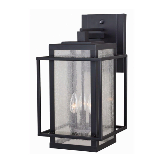
Fixture
Rubber Pad (H)
Ball Nut (G)
Bulb Type B Max.60W
(not included)
Glass Panel
Clip
Glass Frame
181029
Fig.1
Advertisement

Subscribe to Our Youtube Channel
Related Manuals for Vaxcel T0468


Summary of Contents for Vaxcel T0468
- Page 1 ASSEMBLY AND INSTALLATION INSTRUCTIONS T0468 WARNING: TO AVOID RISK OF ELECTRICAL SHOCK, BE SURE TO SHUT OFF POWER BEFORE INSTALLING OR SERVICING THIS FIXTURE. NOTES: 1. Before installing, consult local electrical codes for wiring and grounding requirements. 2. READ AND SAVE THESE INSTRUCTIONS.
- Page 2 4. Pull out the outlet wires and the house grounding wire from the outlet box. Make wire connections using the wire connectors (C): ---Connect the black wire from the fixture to the black wire from the power source. ---Connect the white wire from the fixture to the white wire from the power source. ---Attach the fixture grounding wire to the mounting plate (A) with the green grounding screw (E).
- Page 3 The following parts are available for re-order if damaged or missing. Spare Parts List: Assembly Kit 6000MM (1SET) Mounting plate (A) Mounting Screw (B) Wire Connector (C) Headless screw (D) Glass X 4 10033RG Ball Nut (G) Green Grounding Rubber Pad (H) Lock Nut (F) Screw (E) A: 9-1/2"...
Need help?
Do you have a question about the T0468 and is the answer not in the manual?
Questions and answers