Table of Contents
Advertisement
Quick Links
IMPORTANT: KEEP THIS MANUAL FOR FUTURE REFERENCE
NOTICE
It is the Purchaser's/Owner's obligation:
1. To disclose and post all Rules & Regulations, Danger, Warning and Caution
labels affi xed on the machine to their customers/users.
2. Equipment to be installed by TFI Authorized Dealer or a service
company approved by TFI.
3. Provide trained personnel, supervision and correct usage of the equipment.
4. Provide scheduled inspection, maintenance & repairs and must be performed
by TFI Authorized Dealer or a service company approved by TFI.
5. Must use only genuine TFI replacement parts.
6.
Machine must be anchored to a solid and level surface.
Maintenance & Assembly Instructions
BA-709
LEG PRESS
OWNER'S MANUAL
BA-709_REV2
Revision Date: 7-13-2018
Advertisement
Chapters
Table of Contents

Related Manuals for TuffStuff BIO-ARC BA-709


Summary of Contents for TuffStuff BIO-ARC BA-709
- Page 1 Maintenance & Assembly Instructions IMPORTANT: KEEP THIS MANUAL FOR FUTURE REFERENCE NOTICE It is the Purchaser’s/Owner’s obligation: 1. To disclose and post all Rules & Regulations, Danger, Warning and Caution labels affi xed on the machine to their customers/users. 2. Equipment to be installed by TFI Authorized Dealer or a service company approved by TFI.
-
Page 2: Table Of Contents
Table of Contents OVERHEAD SPECIFICATIONS .................Page 3 DANGER, WARNING, & CAUTION LABELS INFORMATION ....Page 4-7 ANCHORING UNIT .....................Page 8 IMPORTANT SAFETY INSTRUCTIONS ............Page 9 REGISTRATION, SERVICE & ASSEMBLY ............. Page 10 INSPECTION/MAINTENANCE ..............Page 11 CABLE INSPECTION ..................Page 12 STEP 1-8 .......................Page 13-20 STEP 9-10 CABLE ROUTING ..............Page 21-23 STEP 11-12 ....................Page 24-25... -
Page 3: Overhead Specifications
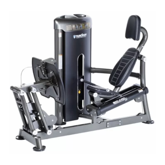
OVERHEAD SPECIFICATIONS L 87” X W 49” X H 58” L 221 cm X W 125 cm X H 148 cm PRODUCT WEIGHT 815 lb/370 kg BA-709 Leg Press www.tuff stuffi tness.com... -
Page 4: Danger, Warning, & Caution Labels Information
Carefully read ALL Danger, Warning & Caution labels posted on the machine Stack them www.tuff stuffi tness.com BA-709 Leg Press... - Page 5 Carefully read ALL Danger, Warning & Caution labels posted on the machine BA-709 Leg Press www.tuff stuffi tness.com...
- Page 6 Carefully read ALL Danger, Warning & Caution labels posted on the machine www.tuff stuffi tness.com BA-709 Leg Press...
- Page 7 Carefully read ALL Danger, Warning & Caution labels posted on the machine It is extremely important that the Facility Sign shown to the left be installed in plain view of the unit. You should have received it along with this Owners Manual. If you did not receive this Facility Sign with your order, you can obtain one at no cost to you from Tuff Stuff Fitness by contacting our service department at:...
-
Page 8: Anchoring Unit
Anchoring Holes on shoes are provided for anchoring the unit to the fl oor. (See anchoring hole locations below) www.tuff stuffi tness.com BA-709 Leg Press... -
Page 9: Important Safety Instructions
Important Safety Instructions It is the responsibility of the facility owner and/or owner of the equipment to review the Owner’s Manual with their facility personnel and understand all Danger, Warning and Caution labels affi xed on the machine. It is the responsibility of the fl oor personnel to instruct users on proper operation of the equipment and review all danger, warning and caution labels. -
Page 10: Registration, Service & Assembly
Registration, Service & Assembly Thank you for purchasing the BA-709 Leg Press. This machine is part of the Tuff Stuff line of quality strength training equipment. To maximize your use of the equipment, please study the Owner’s Manual thoroughly. Allow ample space around the machine for safe unrestricted use and Registration easier access. -
Page 11: Inspection/Maintenance
Inspection/Maintenance Perform regular maintenance (see Inspection Label). Pay special attention to areas most susceptible to wear and tear, including but not limited to cables, pulleys and rubber grip. TFI recommends you maintain a service contract with a TFI Authorized Dealer or a Professional Service Company approved by TFI. -
Page 12: Cable Inspection
Cable Inspection WARNING: THE FOLLOWING CONDITIONS MAY INDICATE A WORN CABLE. REPLACE IMMEDIATELY. “NECKING”, STRETCHED CABLE COVERING A CRACK IN THE CABLE COVER A TEAR IN THE CABLE COVER A BREAK ON THE CABLE CABLE END SLIPPING OUT IMPORTANT NOTE: DAMAGED OR WORN CABLE (AS SHOWN ABOVE) MAY DAMAGE THE PULLEY(S). -
Page 13: Step 1
Step 1 WARNING: Step 1 Assembly List Item # Description Qty. 1. It is strongly recommended BOTTOM CROSS BRACE that two or more persons WEIGHT STACK FRAME FLAT WASHER SAE Z/P 1/2” participate in the assembly FLAT WASHER Z/P 1/2 X 1 3/4 X 3/16 HEX HEAD CAP SCREW Z/P 1/2-13 X 3 1/4 of this unit. -
Page 14: Step 2
Step 2 Step 2 Assembly List Item # Description Qty. TOP CROSS BRACE BUTTON HEAD SOCKET CAP SCREW Z/P 1/2-13 X 1 1/4 FLAT WASHER SAE Z/P 1/2” SPLIT LOCK WASHER Z/P 1/2” Loosely Tighten Loosely Tighten Loosely tighten all hardware in this step. www.tuff stuffi tness.com BA-709 Leg Press... - Page 15 Step 3 Step 3 Assembly List Item # Description Qty. Make sure not to pull out completely. FOOT PLATE HANDLE MAIN FRAME BUTTON HEAD SOCKET CAP SCREW Z/P 1/2-13 X 1 1/4 FLAT WASHER SAE Z/P 1/2” FLAT WASHER SAE Z/P 3/8” HEX HEAD CAP SCREW Z/P 3/8-16 X 1 1/4 SPLIT LOCK WASHER Z/P 1/2”...
- Page 16 Step 4 Step 4 Assembly List Item # Description Qty. ALUMINUM FOOT PLATE FLAT HEAD SOCKET CAP SCREW Z/P 3/8-16 X 1 FLAT WASHER SAE Z/P 3/8” NYLON INSERT LOCK NUT Z/P 3/8-16 RUBBER FOOT PLATE COVER Fully Tighten 100% Fully Tighten Wrench tighten all hardware in this step.
- Page 17 Step 5 Steps 5 Assembly List Item # Description Qty. AXLE 1 RD X 4 3/8 (2X- 3/8-16 THREADED HOLES) AXLE 1 RD X 4 5/8 (2X- 1/2-13 THREADED HOLES) SEAT FRAME ALUMINUM ROUND COVER PLATE, 2 1/2 FLAT HEAD SOCKET CAP SCREW Z/P 1/2-13 X 1 Note: 1.
- Page 18 Step 6 Steps 6 Assembly List Item # Description Qty. HANDLES BUTTON HEAD SOCKET CAP SCREW Z/P 3/8-16 X 3/4 FLAT WASHER SAE Z/P 3/8” SPLIT LOCK WASHER Z/P 3/8” Fully Tighten 100% Fully Tighten Wrench tighten all hardware in this step. www.tuff stuffi tness.com BA-709 Leg Press...
- Page 19 Step 7 Steps 7 Assembly List Item # Description Qty. GUIDE ROD 3/4 X 47 3/4 MAGNETIC SELECTOR PIN W/COIL 3/8 X 5 GOLD KNOB 20 LB STEEL WEIGHT PLATE EA (FLANGED BUSHINGS) FLAT WASHER SAE Z/P 3/8” HEX HEAD CAP SCREW Z/P 3/8-16 X 3 RUBBER DONUT 3/4 RD ID X 2 1/2 RD OD X 3 SPLIT LOCK WASHER Z/P 3/8”...
- Page 20 Step 8 Step 8 Assembly List Item # Description Qty. LABEL-BIO-ARC CIRCULAR WEIGHT STACK NUMBERS Weight stack label and lubrication instructions 1. Wipe front surface of weight stack with rubbing alcohol and wipe dry. 2. Peel off back sheet (adhesive side) from label (#88) and make sure that the label remains attached to the application tape.
-
Page 21: Step 9-10 Cable Routing
Step 9 Cable Routing Note: Steps 9 Assembly List 1. Remove covers #15 and #*15 to perform Item # Description Qty. the following steps. MAIN CABLE BUTTON HEAD SOCKET CAP SCREW Z/P 3/8-16 X 2 2. Remove pulleys specifi ed below to route the FINISHED HEX NUT Z/P 1/2-13 cable and re-assemble when done. -
Page 22: Step 9 Cable Routing
Step 10 Cable Routing Note: 1. Tie guide wire to cable end and pull out indicated below. 2. Make sure cable runs on the pulleys. 3. Adjust cable tension on top plate bolt #129. 4. Re-assemble covers #15 and #*15. SEE FIG A SEE FIG B Pull cable here... -
Page 23: Item # Description Qty
Step 10 Assembly List Item # Description Qty. WEIGHT STACK CABLE BLACK NYLON PULLEY 3/8 X 1 X 3 1/2 BLACK NYLON PULLEY 3/8 X 1 X 4 1/2 BUTTON HEAD SOCKET CAP SCREW Z/P 3/8-16 X 1 3/4 FINISHED HEX NUT Z/P 1/2-13 FLAT WASHER SAE Z/P 3/8”... - Page 24 Step 11 Step 11 Assembly List Item # Description Qty. SHIELD, REAR SHIELD, FRONT FLAT HEAD SOCKET CAP SCREW Z/P 1/4-20 X 3/4 *138 TOP PLASTIC COVER, WEIGHT STACK FRAME *138 Fully Tighten 100% Fully Tighten Wrench tighten all hardware in this step. www.tuff stuffi tness.com BA-709 Leg Press...
- Page 25 Step 12 Step 12 Assembly List Item # Description Qty. STANDARD PAD HEAD REST PAD SEAT PAD BUTTON HEAD SOCKET CAP SCREW Z/P 3/8-16 X 1 1/4 FLAT WASHER SAE Z/P 3/8” Fully Tighten 100% Fully Tighten Wrench tighten all hardware in this step. BA-709 Leg Press www.tuff stuffi tness.com...
-
Page 26: Parts List
BNH3088 UP9008 REAR FULCRUM UP9009 LABEL SERIAL NUMBER CLASS S BNH5186 REAR FULCRUM W/CABLE TENSION LABEL TFI TUFFSTUFF FITNESS INTERNATIONAL UP9010 BNH3777 REAR LINEAR SHAFT 1 RD. X 24 LABEL WARNING ANCHOR BOLT, 2 X 1 1/4 UP9011 BNH3089 CARRIAGE... - Page 27 Parts List Continued Item No. Description Rev. Part No. Qty. Item No. Description Rev. Part No. Qty. RUBBER GRIP 1 ID X .125 X 5 BNH0957 TENSION CAM BNH3768 RUBBER SHOE FOR 1/4 X Ø 5 3/8 PLATE BNH4361 TEXTURED RUBBER MAT LEFT (STRONG ADHESIVE) BNH3812 SHOULDER BOLT ALLOY 3/8 X 1/4 TEXTURED RUBBER MAT RIGHT (STRONG ADHESIVE)
-
Page 28: Pre Assembled Components
Pre Assembled Components www.tuff stuffi tness.com BA-709 Leg Press... - Page 29 Pre Assembled Components *28 UP9014X1 *12 UP8998X1 *30 UP8918X9 BNH3532X9 *138 135 136 BA-709 Leg Press www.tuff stuffi tness.com...
- Page 30 Pre Assembled Components *36 UP8921X1 BNH3539X1 *132 *38 BNH3534 *17 UP9001X1 www.tuff stuffi tness.com BA-709 Leg Press...
-
Page 31: Release Cable Replacement
Release Cable Replacement Step 4 Assembly List STEP 2 Item # Description Qty. COVER PLATE FOOT PLATE HANDLE BUTTON HEAD SOCKET CAP SCREW Z/P 1/4-20 X 1/2 FLAT WASHER SAE Z/P #12 (1/4”) FLAT WASHER SAE Z/P 1/2” HEX HEAD CAP SCREW Z/P 1/2-13 X 1/2 (SPLIT) PLUNGER 1/2 X 3 1/16 PLUNGER 1/2 X 2 1/4 PULL PIN LIGHT SPRING 17/32 X 1 1/2 K-105... -
Page 32: Warranty
Website: www.tuffstuffitness.com This warranty applies only in the United States to the products manufactured or distributed by TuffStuff Fitness International Inc. under the TUFFSTUFF brand name. TuffStuff warrants to the original purchaser that TuffStuff equipment will be free from defects in material and workmanship. All warranty periods begin to run from the date of purchase to the original purchaser.
Need help?
Do you have a question about the BIO-ARC BA-709 and is the answer not in the manual?
Questions and answers