Table of Contents
Advertisement
Quick Links
O W N E R ' S
TABLE OF CONTENTS:
Introduction - Pg. 1
Safety Precautions - Pg. 2
Assembly for BRT-1 - Pg. 3 - Pg. 17
Cable Adjustments - Pg. 18
Pg. 19 - Pg. 20
Parts List - Pg. 21
Exploded View Diagram
Fold-Out Pg. 22
Adjustment Features - Pg. 23- Pg. 25
Basic Exercises - Pg. 26
Maintenance - Pg. 27
Warranty - Back Page
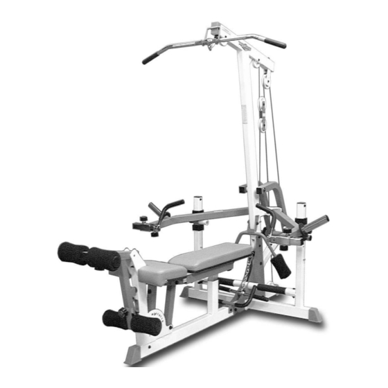
BRT-1
"The Brute" Plate Loaded
Home Gym
© 2003 TASK INDUSTRIES, INC.
A m e r i c a ' s
P r e m i u m
M A N U A L
63"
L 99" W 63" H 83"
E x e r c i s e
E q u i p m e n t
Revision Date 02-05-02
99"
BRT-1 Rev. 1
Advertisement
Table of Contents

Related Manuals for TuffStuff BRT-1


Summary of Contents for TuffStuff BRT-1
- Page 1 M A N U A L TABLE OF CONTENTS: Introduction - Pg. 1 Safety Precautions - Pg. 2 Assembly for BRT-1 - Pg. 3 - Pg. 17 Cable Adjustments - Pg. 18 Cable Mapping Diagrams Pg. 19 - Pg. 20 Parts List - Pg.
- Page 2 Congratulations on your new purchase of the “The Brute” Plate the correct assembly and safe use of this Product, as-well-as to Loaded Home Gym (BRT-1). This gym is capable of a variety of prevent injury to yourself or anyone else.
-
Page 3: Safety Precautions
Turn/Pull Pins w/Knob (#42) and the Push Pull Pins (#43) to be fully engaged into the selected holes of their semblies. Refer to Fig. 3 for further illustration of this in- corresponding assemblies. struction. BRT-1 “The Brute” Plate Loaded Home Gym... - Page 4 Note: When positioning the Base Frame (#1) consider the complete area surface of the BRT-1. Use the overhead view on Loosely Fasten: Do not completely fasten this hardware assembly NOTE: at this time, as it will be completely fastened later in the assembly the cover page for designing your layout before assembling.
- Page 5 (#3), use a measuring tape. The measurement from the NOTE: edge of the Triangular Reinforcement Plate (#2, or #113) to the inner edge of the Safety Anti-Slip Tape (#40), as picture above, should be about 3 3/8” BRT-1 “The Brute” Plate Loaded Home Gym...
- Page 6 Screw 1/2-13 X 5 1/2 (#73), two Flat Washers SAE 1/2” (#68), and one sert Jam Lock Nuts 3/8-16 (#85). Nylon Insert Jam Lock Nut 1/2-13 (#75). Repeat the same procedure for Left Press Arm (#8). BRT-1 “The Brute” Plate Loaded Home Gym...
- Page 7 Weight Carriage (#10) two supplied Hex Keys 7/32” (#94) to fasten this assembly properly. the receptacle of the Main Frame (#5) until it is flush with both sides of the Weight Carriage (#10). BRT-1 “The Brute” Plate Loaded Home Gym...
- Page 8 Set Screws 1/4-20 X 3/8 (#41). Use the supplied Head Cap Screw 3/8-16 X 2 3/4 (#80), two Flat Washers SAE 3/8” (#84), Hex Key 1/8” (#93) to fasten these Set Screws. and one Nylon Insert Jam Lock Nut 3/8-16 (#85). BRT-1 “The Brute” Plate Loaded Home Gym...
- Page 9 Note: The four holes on the Closed-end Adj. Double Pulley detailed illustration of the Lat Cable (#31) routing. Bracket (#33) are used to adjust the cable tension once the cable NOTE: NOTE: routing has been completed. BRT-1 “The Brute” Plate Loaded Home Gym...
- Page 10 Shoulder Bolt 3/8 X 3/4 (#86), and one Nylon Insert Lock Nut 5/16-18 (#99). Note: To facilitate the insertion of these Rubber Bumper Washers (#101), use Windex or household glass cleaner. NOTE: BRT-1 “The Brute” Plate Loaded Home Gym...
- Page 11 16 (#85). detailed illustration of the Leg Extension Cable (#32) routing. NOTE: Note: Refer to the Cable Mapping Diagram on page 20 for further detailed illustration of the Leg Extension Cable (#32) routing. NOTE: BRT-1 “The Brute” Plate Loaded Home Gym...
- Page 12 Leg Extension Cable (#32) routing. NOTE: ing the path as illustrated with the arrows . Note: Refer to Fig D on page 20 for further clarification of this as- sembly. NOTE: BRT-1 “The Brute” Plate Loaded Home Gym...
- Page 13 Hex Head Cap Screws 1/2-13 X 4 (#71), four Flat Wash- 1/2” (#68), and one Nylon Insert Jam Lock Nut 1/2-13 (#75). ers SAE 1/2” (#68), and two Nylon Insert Jam Lock Nuts 1/2-13 (#75). BRT-1 “The Brute” Plate Loaded Home Gym...
- Page 14 Channels. in the position as shown above, to the Channel Seat Frame (#13) and the Incline Bench Elevation Tube (#15). BRT-1 “The Brute” Plate Loaded Home Gym...
- Page 15 Incline Bench Channels 16 X 1 1/4 (#76), and two Flat Washers SAE 3/8” (#84). (#16, #17) using four Hex Head Cap Screws 3/8-16 X 3 1/2 (#82), and four Flat Washers SAE 3/8” (#84). BRT-1 “The Brute” Plate Loaded Home Gym...
- Page 16 Press Arms (#8, #9). Be sure to disengage the Turn/Pull Pin w/Knob (#42) as you insert the Exten- sion Arm Tubes (#25, #26) into the receptacles of the left and right Press Arms (#8, #9). BRT-1 “The Brute” Plate Loaded Home Gym...
- Page 17 Foot Roll Tubes (#21). 1” (#62), in the position as shown above, into each tube end of the two Foot Roll Tubes (#21). BRT-1 “The Brute” Plate Loaded Home Gym...
- Page 18 Turn/Pull Rest the Low Row Bar (#36) onto the notch located on Triangular Rein- Pins (#42) forcement Plates when not in use. BRT-1 “The Brute” Plate Loaded Home Gym...
- Page 19 3. Re-tighten the hardware for the Nylon Pulley (#64-Labeled F) to complete the cable ad- justment. Fully Fasten: Proceed to Fully Fasten these hardware assemblies and all of the previous assem- blies that were left loosely fastened. FULLY FASTEN BRT-1 “The Brute” Plate Loaded Home Gym...
- Page 20 BRT-1 “The Brute” Plate Loaded Home Gym...
- Page 21 BRT-1 “The Brute” Plate Loaded Home Gym...
- Page 22 CHROME CAP 1 7/8" RD BNH1016 HEX HEAD CAP SCREW GR-5 B/O 3/8-16 X 1 1/2 BNH0303 PLASTIC END CAP 2" RD. BNH0001 TRIANGULAR REINFORCEMENT PLATE LEFT UP844 PLASTIC INSERT CAP 1-3/4" SQ. 10-14 GA. BNH0053 BRT-1 “The Brute” Plate Loaded Home Gym...
- Page 23 4. Release the Push Pull Pin 1/2 X 3 1/2 (#43) and make sure it fully en- ♦ C, D used for Incline Positon gages into the selected hole of the Incline Bench Elevation Tube (#15). BRT-1 “The Brute” Plate Loaded Home Gym...
- Page 24 4. Release the Push Pull Pin (#43) and make sure it fully engages into the hole of the Leg Hold Down Frame (#22). Note: Bring the Leg Hold Down Frame (#22) to the lower position when not in use. NOTE: BRT-1 “The Brute” Plate Loaded Home Gym...
- Page 25 Handle Housing Tubes (#28, #29) Settings: FIG. 75 Foot Roll (#61) Settings: Adjustable Handle Housing Tubes Gradual Range of Adjustments ac- Foot Rolls Gradual Range of Adjustments accommodate for individual leg commodate for various body widths. lengths. BRT-1 “The Brute” Plate Loaded Home Gym...
- Page 26 TuffStuff. Limitations: The foregoing shall constitute the sole remedy of the purchaser and the sole liability of TuffStuff with regard to warranty, whether express or implied by operation of law or otherwise, including but not limited to any implied warranties of merchantability or fitness.
Need help?
Do you have a question about the BRT-1 and is the answer not in the manual?
Questions and answers