Sign In
Upload
Manuals
Brands
janitza Manuals
Measuring Instruments
UMG 801
janitza UMG 801 Manuals
Manuals and User Guides for janitza UMG 801. We have
3
janitza UMG 801 manuals available for free PDF download: User Manual And Technical Data, User Manual, Manual
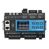
janitza UMG 801 User Manual And Technical Data (140 pages)
Modular Power Analyzer
Brand:
janitza
| Category:
Measuring Instruments
| Size: 17 MB
Table of Contents
Table of Contents
4
1 Information on the Device and the User Manual
12
Disclaimer
12
Copyright Notice
12
Technical Changes
12
About this User Manual
12
Defective Device/Disposal
13
2 Safety
14
Display of Warning Notices and Safety Information
14
Hazard Levels
14
Product Safety
14
Dangers When Handling the Device
15
Electrically Qualified Personnel
16
Warranty in the Event of Damage
16
Safety Information for Handling Current Transformers
16
Safety Information for Handling Measurement Devices with Residual Current Measurement
17
Handling Batteries/Accumulators
17
3 Product Description
18
Device Description
18
Incoming Goods Inspection
19
Intended Use
19
Performance Characteristics
20
EU/UKCA Declaration of Conformity
20
FCC Declaration of Conformity
20
Scope of Delivery
21
Accessories
21
Measuring Method
22
Transformers
22
Operating Concept
22
Web Server with Device Homepage
23
Gridvis Network Analysis Software
23
Overview of the Range of Functions
23
Configuration on the Device (Via 6 Buttons)
23
Communication
23
Measured Values (with Voltage Component)
24
Measured Values (with Current Component)
24
4 Structure of the Device
26
Front Panel and Display
26
Side Views
28
Bottom View
28
Identification of the Device (Rating Plate)
29
5 Mounting
30
Installation Location
30
Bus Connector
31
DIN Rail Mounting of the Device
31
6 Grid Systems
33
7 Installation
34
Nominal Voltages
34
Circuit Breaker
35
Supply Voltage
35
Voltage Measurement
36
Overvoltage
36
Mains Frequency
36
Connection Variants for Voltage Measurement
37
Current Measurement
38
Connection Variants for Current Measurement
39
Summation Current Measurement
40
Ammeter
40
Multifunction Channels
40
Residual Current Measurement (RCM)
41
Current Direction of the Residual Current Transformers
42
Residual Current Transformer Example
42
Important Information about the Residual Current Measurement Inputs
42
Connection Examples - Residual Current Measurement
43
Connection Example - Residual Current Monitoring
44
Residual Current Measurement - Limit Value Calculation
45
Static Limit Value Calculation
45
Dynamic Limit Value Calculation
46
Stepwise Limit Value Calculation
47
Example: Residual Current Limit Value Exceeded
48
Activating Cable Break Detection (Failure Monitoring) RCM for the Multifunction Channels
49
Temperature Measurement
50
8 Communication Via the Ethernet Interfaces
52
Functions of the Ethernet Interfaces
52
Switched Mode" Connection Option
53
Dedicated Mode" Connection Option
53
Meaning of the Ethernet Interface Leds
53
9 PC Connections and Other Interfaces
54
PC Connections
54
Interface (Serial Interface)
56
Shielding
57
Termination Resistors/Termination
57
Bus Structure (Bus Segment)
58
Janbus Interface
58
Digital Inputs
59
Digital Outputs
60
Analog Outputs
61
10 Operation and Button Functions
62
Controls
62
Function Buttons
62
Measuring Display
62
Menu
62
PIN (Password)
63
Overview of Menu Displays
64
11 Configuration
66
The Configuration Window
66
Configuring Ethernet (TCP/IP)
66
Communication Via TCP/IP
67
Communication Via OPC UA
67
Configuring the Fieldbus (RS-485 Interface)
68
Communication Settings
68
Configuring Current Transformers
69
Configuring Voltage Transformers
70
Temperature Measurement Configuration
71
Temperature Sensor Types
71
Temperature Offset" Item
71
Configuring the Display
72
Language
72
Standby (After)
72
Brightness
73
Configuring the System
73
Pin
73
Restart (Reboot)
74
Time
74
Date
74
Reset
75
Standard Factory Settings
75
Reset Configuration
75
Reset Minimum, Maximum and Average Values
76
Reset Energy Values
76
Reset Historical Data
77
Module Identification / Diagnostics
77
Events and Transients
78
Events
78
Transients
78
Event and Transient Recording
79
Configuration of the Waveform for Events and Transients
80
Half-Wave RMS Values for Events
80
Update Time for Transients
81
Configuration in the Gridvis Software
81
12 Digital Inputs and Outputs
82
Digital Inputs
82
Digital Outputs
84
13 Analog Outputs
86
14 Commissioning
88
Supply Voltage
88
Measured Voltage
88
Measured Current
89
Frequency Measurement
89
Direction of Rotary Field
90
Fundamentals on the Phasor Diagram
90
Checking of Voltage and Current Inputs by Means of Phasor Diagram
91
Checking the Phase Assignment
91
Checking the Power Measurement
91
Checking Measurement
92
Checking Individual Power
92
Checking Summation Power
92
Drag Indicator Function
93
Configuring the Drag Indicator Synchronization
93
Drag Indicator - Measurement Device Display
95
Resetting the Drag Indicator
96
Average Value - Gridded and Moving
96
Gridded Average Value
96
Moving Average Value
97
Gridded and Moving Average in the Gridvis ® Software
97
15 Overview of Measured Value and Meter Displays
98
16 Connection Example
112
17 Dismounting
113
18 Device Homepage
114
Home" Start Page
114
Login
115
Change Password
116
Measured Values" Menu Bar Item
117
Details
117
Events and Transients
118
Settings" Menu Bar Item
119
Firmware Update
120
Whitelist (Modbus Port 502)
121
Information" Menu Bar Item
122
Device Information
122
Modbus Address List
123
Imprint
123
19 Service and Maintenance
124
Repair and Calibration
124
Front Panel Foil and Display
124
Service
124
Device Adjustment
125
Firmware Update Via the Device Homepage
125
Firmware Update Via the Gridvis Software
125
Clock/Battery
125
Battery Replacement
125
20 Error Messages
126
Overrange
126
Procedure in the Event of a Malfunction
127
21 Technical Specifications
128
Technical Data
128
Performance Characteristics of Functions
134
Parameter and Modbus Address List
135
Information on Saving Measured Values and Configuration Data
135
22 Dimensional Drawings
136
Basic Device UMG
136
Bus Connector
137
Advertisement
janitza UMG 801 User Manual (106 pages)
Modular Power Analyzer
Brand:
janitza
| Category:
Measuring Instruments
| Size: 13.44 MB
Table of Contents
Table of Contents
4
Information on the Device and the User Manual
10
Disclaimer
10
Copyright Notice
10
Technical Changes
10
About this User Manual
10
Defective Device/Disposal
11
Safety
12
Display of Warning Notices and Safety Information
12
Hazard Levels
12
Product Safety
13
Dangers When Handling the Device
13
Electrically Qualified Personnel
14
Warranty in the Event of Damage
14
Safety Information for Handling Current Transformers and Measurement Devices with Residual Current Measurement
14
Handling Batteries/Accumulators
15
Product Description
16
Device Description
16
Incoming Goods Inspection
16
Intended Use
17
Performance Characteristics
18
EU Conformity Declaration
18
Scope of Delivery
19
Accessories
19
Measuring Method
20
Operating Concept
20
Gridvis Network Analysis Software
20
Overview of the Range of Functions
21
Configuration on the Device (Via 6 Buttons)
21
Communication
21
Measured Values (with Voltage Component)
21
Measured Values (with Current Component)
22
Structure of the Device
24
Front Panel and Display
24
Side Views
26
Bottom View
26
Identification of the Device (Rating Plate)
27
Mounting
28
Installation Location
28
Mounting Orientation and Attachment
28
Grid Systems
30
Installation
32
Nominal Voltages
32
Three-Phase 4-Conductor Network with Grounded Neutral Conductor
32
Disconnect Switch
32
Supply Voltage
33
Voltage Measurement
34
Overvoltage
35
Mains Frequency
35
Connection Variants for Voltage Measurement
36
Current Measurement
37
Connection Variants for Current Measurement
38
Summation Current Measurement
39
Ammeter
39
Multifunction Channels
40
Residual Current Measurement (RCM)
40
Current Direction of the Residual Current Transformers
41
Residual Current Transformer Example
42
Important Information about the Residual Current Measuring Inputs
42
Connection Examples - Residual Current Measurement
43
Connection Example - Residual Current Monitoring
44
Temperature Measurement
45
PC Connection
46
Connection to a PC
46
Peripherals
48
Ethernet Interface
48
Daisy Chain Connection
48
Interface (Serial Interface)
49
Shielding
50
Termination Resistors/Termination
50
Bus Structure (Bus Segment)
51
Janbus Interface
51
Digital Inputs
52
Digital Outputs
54
Analog Outputs
55
Operation and Button Functions
56
Controls
56
Function Buttons
56
Measuring Display
56
Menu
56
PIN (Password)
57
Overview of Menu Displays
58
Configuration
60
The Configuration Window
60
Configuring Ethernet (TCP/IP)
60
Communication Settings
61
Communication Via OPC UA
61
Configuring the Fieldbus (RS-485 Interface)
62
Communication Settings
62
Configuring Current Transformers
63
Configuring Voltage Transformers
64
Configuring the Display
65
Language
65
Standby (After)
65
Configuring the System
66
Pin
66
Brightness
66
Time
67
Date
67
Reset
68
Standard Factory Settings
68
Restart
68
Reset Minimum, Maximum and Average Values
69
Digital Inputs and Outputs
70
Digital Inputs
70
Digital Outputs
72
Analog Outputs
74
Commissioning
76
Supply Voltage
76
Measured Voltage
76
Measured Current
77
Frequency Measurement
77
Direction of Rotary Field
78
Fundamentals on the Phasor Diagram
79
Checking of Voltage and Current Inputs by Means of Phasor Diagram
80
Checking the Phase Assignment
80
Checking the Power Measurement
80
Checking Measurement
80
Checking Individual Power
80
Checking Summation Power
81
Overview of Measured Value and Meter Displays
82
Connection Example
90
Service and Maintenance
92
Repair and Calibration
92
Front Panel Foil and Display
92
Service
92
Device Adjustment
93
Firmware Update
93
Clock/Battery
93
Battery Replacement
93
Error Messages
94
Overrange
94
Procedure in the Event of a Malfunction
95
Technical Data
96
Performance Characteristics of Functions
102
Parameter and Modbus Address List
103
Information on Saving Measured Values and Configuration Data
103
Dimensional Drawings
104
janitza UMG 801 Manual (16 pages)
Power Analyser
Brand:
janitza
| Category:
Measuring Instruments
| Size: 20.57 MB
Advertisement
Advertisement
Related Products
janitza UMG 804
janitza UMG 806
janitza UMG 503
janitza UMG 104
janitza UMG 96
janitza UMG 604-PRO
janitza UMG 103-CBM
janitza UMG 96 RM-EL
janitza UMG 96S 24V
janitza UMG 96-S2
janitza Categories
Measuring Instruments
Control Unit
Controller
Touch Panel
Transformer
More janitza Manuals
Login
Sign In
OR
Sign in with Facebook
Sign in with Google
Upload manual
Upload from disk
Upload from URL