
Related Manuals for janitza UMG 96 RM-PN


Summary of Contents for janitza UMG 96 RM-PN
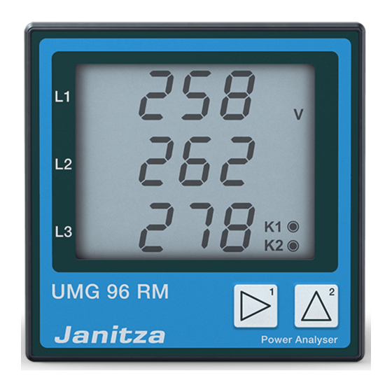
- Page 1 Power Analyser UMG 96 RM-PN User manual and technical data Power Analyser Janitza electronics GmbH Vor dem Polstück 6 D-35633 Lahnau Support tel. +49 6441 9642-22 Fax +49 6441 9642-30 E-mail: info@janitza.com www.janitza.com...
-
Page 2: Table Of Contents
UMG 96RM-PN Table of contents General information Configuration Inspection on receipt Connecting the supply voltage Available accessories Current and voltage transformer Product description Programming the current transformer for I1-I3 51 Proper use Programming the voltage transformer UMG 96RM-PN features Programming parameters Measuring process TCP/IP configuration Operating concept... - Page 3 UMG 96RM-PN Serial number (addr. 754) Technical data Software release (addr. 750) Function parameters Commissioning Table 1 - Parameter list Connecting the supply voltage Table 2 - Modbus address list Connecting the measured voltage Number formats Applying the measuring-circuit voltage Dimension diagrams Direction of the rotating field Measured value screen overview...
-
Page 4: General Information
- nor otherwise duplicated or This manual uses the following pictograms: republished, without the binding written permission of: Janitza electronics GmbH, Vor dem Polstück 1, D 35633 Lahnau, Germany Dangerous voltage! Risk to life or serious injury. Before... - Page 5 UMG 96RM-PN Instructions on use Please read this operation manual as well as all other can be caused by the operation or maintenance of the device. publications that must be consulted for working with this product (in particular, for the installation, operation or Additional legal and safety regulations required for maintenance).
-
Page 6: Inspection On Receipt
UMG 96RM-PN Inspection on receipt Concerning this operation manual This operation manual is part of the product. The prerequisites of faultless, safe operation of this • Read the operation manual before using the device. device are proper transport and proper storage, set- •... -
Page 7: Available Accessories
UMG 96RM-PN Available accessories Number Part no. Designation 52.22.251 Mounting clips 10.01.855 Screw-type terminal, pluggable, 2-pole (auxiliary power) 10.01.849 Screw-type terminal, pluggable, 4-pole (voltage measurement) 10.01.871 Screw-type terminal, pluggable, 6-pole (current measurement I1-I3) 10.01.875 Screw-type terminal, pluggable, 2-pole (current measurement I4) 10.01.865 Screw-type terminal, pluggable, 10-pole (digital/analogue inputs/outputs) 10.01.857... -
Page 8: Product Description
UMG 96RM-PN Product description Proper use A continuous monitoring of residual currents (residual The UMG 96RM-PN is intended for the measurement current monitor, RCM) is performed via the current and calculation of electrical variables such as voltage, measurement inputs I5 and I6 via an external residual current, power, energy, harmonics, etc. - Page 9 UMG 96RM-PN Device parameters • Supply voltage: Option 230V: 90V - 277V (50/60Hz) or DC 90V - 250V; 300V CATIII Option 24V: 24 - 90V AC / DC; 150V CATIII • Frequency range: 45 - 65 Hz Device functions • 3 voltage measurement channels, 300V •...
-
Page 10: Umg 96Rm-Pn Features
UMG 96RM-PN UMG 96RM-PN features General information • Measurement in networks with rated voltages up • Front panel integration device with dimensions to L-L 480V and L-N 277V 96x96 mm • Measurement range current 0 to 5A eff. • Connection via pluggable screw terminals •... -
Page 11: Measuring Process
GridVis network analysis software (Download: interval. The device measures the real effective value www.janitza.com). For this, a PC must be connected to (TRMS) of the voltages and currents connected to the UMG 96RM-PN via a serial interface (RS485) or by the measurement inputs. -
Page 12: Connection Variants
RS485 UMG 96RM-PN Connection variants RS485 Direct connection of a UMG 96RM-PN to a PC/PLC via Connection of a UMG 96RM-PN to a PC via an interface Ethernet/ProfiNet. converter: Ethernet RS485 RS485 (GridVis) RS485 Ethernet / ProfiNet (GridVis) Ethernet / ProfiNet UMG 96RM-PN UMG 96RM-PN RS485... -
Page 13: Assembly
UMG 96RM-PN Assembly Position of installation The UMG 96RM-PN is suitable for integration into fixed and weatherproof switch panels. Conductive switch panels must be earthed. Mounting position To ensure adequate ventilation, the UMG 96RM-PN must be installed vertically. There should be separation above and below of at least 50mm with 20mm space to the sides. - Page 14 UMG 96RM-PN Mounting The UMG 96RM-PN is secured in the switchboard Mounting is then performed by sliding in and engaging by the mounting clips on the side. Before insertion the clips and subsequently screwing in the screws. the device they must be removed, for example by using a screwdriver to lever them horizontally.
-
Page 15: Installation
UMG 96RM-PN Installation Supply voltage The UMG 96RM-PN needs a supply voltage to operate. The supply voltage is connected on the rear side of the device via terminal blocks. Fuse Before connecting the supply voltage, ensure that Circuit breaker the voltage and frequency correspond to the details on the rating plate! •... -
Page 16: Voltage Measurement
UMG 96RM-PN Voltage measurement You can use the UMG 96RM-PN for voltage measurement In systems with no N, measured values requiring an N in TN, TT, and IT systems. refer to a calculated N. Voltage measurement in the UMG 96RM-PN is designed for the overvoltage category 300V CAT III (measurement voltage surge 4kV). - Page 17 UMG 96RM-PN Nominal network voltage Lists of networks and their nominal network voltages in which the UMG 96RM-PN can be used. Three-phase 4-conductor systems with Unearthed three-phase 3-conductor systems. earthed neutral conductor. L-N / 66V / 115V 120V / 208V 120V 127V / 220V 127V...
- Page 18 UMG 96RM-PN Voltage measurement inputs The UMG 96RM-PN has three voltage measurement inputs (V1, V2, V3). Overvoltage The voltage measurement inputs are suitable for measurements in networks where overvoltages of overvoltage category 300V CATIII (measurement voltage surge 4kV) can occur. Fuse Frequency The UMG 96RM-PN requires the mains frequency for...
- Page 19 UMG 96RM-PN When connecting the voltage to be measured, Attention! the following must be observed: Voltages that exceed the allow nominal network voltages must be connected Isolation device via a voltage transformer. • A suitable circuit breaker must be fitted to disconnect and de-energise the UMG 96RM-PN.
- Page 20 UMG 96RM-PN Connection schematics, voltage measurement • 3p 4w (addr. 509= 0), factory default setting • 3p 4wu (addr. 509 = 1) Fig. System with three phase conductors and Fig. System with three phase conductors and a neutral conductor. a neutral conductor. Measurement made with a voltage transformer.
- Page 21 UMG 96RM-PN • 1p 2w1 (addr. 509 = 4) • 2p 4w (addr. 509 = 3) Fig. Measured values derived from voltage Fig. System with equal loading of the phases. measurement inputs V2 and V3 are taken to be The measured values for voltage measurement zero and are not calculated.
-
Page 22: Current Measurement Using I1 To I4
UMG 96RM-PN Current measurement using I1 to I4 The UMG 96RM-PN is intended for the connection of current transformers with secondary currents of ../1A and ../5A, via terminals I1-I4. The factory default for the current transformer ratio is 5/5A and must be adapted to the current transformer employed if necessary. - Page 23 UMG 96RM-PN Earthing of current transformers! If a connection is provided for the earthing of secondary windings, then it must be connected to the earth. Attention! The UMG 96RM-PN is not suitable for measuring DC voltages. It is not necessary to configure a connection schematic for measurement input I4.
- Page 24 UMG 96RM-PN Current direction The current direction can be individually corrected via Attention! the existing serial interfaces or on the device for each Residual current monitoring is performed phase. using the terminals I5 and I6 (cf. page If incorrectly connected, a subsequent re-connection of 30).
- Page 25 UMG 96RM-PN Attention! The UMG96RM is only approved for measuring current with a current transformer.
- Page 26 UMG 96RM-PN Connection schematics, current measurement (I1-I3) • 3p 4w (addr. 510= 0), factory default setting • 3p 2i (addr. 510 = 1) Fig. Measurement in a three-phase network with Fig. System with equal loading of the phases. unequal loading. The measured values for current measurement input I2 are measured.
- Page 27 UMG 96RM-PN • 3p 3w (addr. 510 = 4) • 2p 4w (addr. 510 = 5) Fig. System with equal loading of the phases. Fig. System with equal loading of the phases. The measured values for current measurement The measured values for current measurement inputs I2 and I3 are calculated.
- Page 28 UMG 96RM-PN Connection schematics, current measurement (I1-I3) Ammeter If you wish to measure the current not only with the UMG • 3p 1w (addr. 510 = 8) 96RM but rather with an ammeter too, the ammeter must be connected to the UMG 96RM-PN in series. Fig.
- Page 29 UMG 96RM-PN Total current measurement Example: The current is measured via two current If the current measurement is done via two current transformers. Both current transformers have a transformers, the overall transformation ratio of transformation ratio of 1000/5A. The summation the current transformers must be programmed into measurement is performed using a total current the UMG 96RM-PN.
-
Page 30: Analogue Inputs
UMG 96RM-PN Analogue inputs Attention! Operating equipment connected to The UMG 96RM-PN has two analogue inputs, each of the analogue inputs must feature which can be used for a residual current measurement reinforced or double insulation to the or a temperature measurement. A measurement is mains supply circuits! performed here via terminals 32-34 (Input 1) and 35-37 (Input 2). -
Page 31: Residual Current Monitoring (Rcm) Via I5, I6
UMG 96RM-PN Residual current monitoring (RCM) via I5, I6 The UMG 96RM-PN is suitable for use as a residual current monitoring device (RCM) as well as for monitoring AC, pulsing DC, and DC. The UMG 96RM-PN can measure residual currents in accordance with IEC/TR 60755 (2008-01) of type A and type B. - Page 32 UMG 96RM-PN Connection example, residual current monitoring Residual current transformer Residual current transformer Fig. Example L1 L2 L3 N UMG96RM-PN with residual current UMG 96RM-PN monitoring via measuring inputs I5/I6. It is not necessary to configure a connection schematic for measurement inputs I5 and I6!
-
Page 33: Thermistor Input
UMG 96RM-PN Thermistor input The UMG 96RM-PN has two thermistor inputs. The temperature measurement is performed here via terminals 32/34 (Input 1) and 35/37 (Input 2). Do not exceed the total resistance load (sensor + cable) of 4kOhm. PT100 PT100 Use a shielded cable to connect the Fig. -
Page 34: Rs485 Interface
UMG 96RM-PN RS485 interface Termination resistors On the UMG 96RM-PN, the RS485 interface is designed The cable is terminated with resistors (120Ohm, 1/4W) at as a 2-pin plug contact, which communicates via the the beginning and at the end of a segment. Modbus RTU protocol (see also Programming parameters). - Page 35 UMG 96RM-PN Screening Cable type Twisted screened cable should be used for connections The cable used must be suitable for an environmental via the RS485 interface. temperature of at least 80°C. • Earth the screens of all cables that lead to the cabinet Recommended cable types: and at the cabinet entry.
- Page 36 UMG 96RM-PN Bus structure • All devices are connected in a bus structure (line) and • It is recommended that the master be placed at each device has its own address within the bus (see the end of a segment. also Parameter programming).
-
Page 37: Ethernet / Profinet Interface
UMG 96RM-PN Ethernet / ProfiNet interface The Ethernet network settings should be specified by The UMG 96RM-PN has two identical Ethernet interfaces. the network administrator and set on the UMG 96RM- This allows another Ethernet/ProfiNet terminal to be PN accordingly. operated via the second interface, thus reducing outlay If the network settings are not known, the UMG 96RM- on cabling. - Page 38 ProfiNet characteristics of the UMG96RM- PN. The GSD file is required, for example, by the configuration program of the PLC. The device master file for the UMG96RM-PN has the file name "GSDML-V2.31-JanitzaelectronicsGmbH- UMG96RM-PN-xxxxxxxx.xml" (Download: www.janitza. com).
-
Page 39: Digital In-/Outputs
UMG 96RM-PN Digital in-/outputs The UMG 96RM-PN has 2 digital outputs and either Digital outputs, Group 2 • The status of the inputs and outputs in Group 2 is 3 digital inputs or outputs, which are subdivided into two groups (see Figure, page 40). This is based on indicated by the associated LED (cf. - Page 40 UMG 96RM-PN Input/output byte coding (Input/output data of the ProfiNet „digital IO“ module) • If the digital inputs/outputs in group 2 are configured as inputs, bit-oriented coding of the statuses occurs (bit 0 to 2). In this case, coding corresponds to the digital inputs with: Input 3: 1 = signal is present Input 2: 1 = signal is present...
- Page 41 UMG 96RM-PN Digital outputs Group 2 These outputs galvanically separated from the analysis electronics using optocouplers. The digital outputs have a common supply. • The digital outputs of group 1 can switch AC and DC loads. The digital outputs of group 2 can not switch AC loads.
- Page 42 UMG 96RM-PN Example DC connection External Attention! UMG 96RM-PN auxiliary voltage Digital outputs are not short-circuit proof! 24V DC Digital Ouput 1 Functions for the digital outputs can be adjusted clearly in the GridVis software. A connection between the UMG 96RM-PN Digital Ouput 2 and the PC via an interface is required to use the GridVis software.
- Page 43 UMG 96RM-PN Digital inputs When Group 2 is assigned as inputs, the UMG96 RM- PN has three digital inputs, each of which can have External a signal generator connected to it. If there is a signal, auxiliary voltage 24V DC the associated LED lights up green.
-
Page 44: Led Status Bar
UMG 96RM-PN LED status bar The LED status bar on the back of the device shows Digital input/output 1/3 the different statuses of the inputs and outputs. Digital input/output 2/4 Digital input/output 3/5 Digital inputs The LED assigned to the input lights up green if a signal of at least 1mA is fl owing on this interface. -
Page 45: Operation
UMG 96RM-PN Operation Programming mode Programming mode displays allows The UMG 96RM-PN is operated with buttons 1 and 2, the modification of the settings required for operation whereby the following distinctions are made: of the UMG 96RM-PN. Pressing and holding buttons 1 •... - Page 46 UMG 96RM-PN Max. value, HT/Consumption Min. value NT/Delivery Mean value Programming mode Summation measurement Phase conductor- Phase conductor Password CT: Current transformer VT: Voltage transformer K1: Output 1 K2: Output 2 Button 2 Delivery Button 1...
-
Page 47: Parameters And Measured Values
UMG the list) the device address of 96RM-PN. the UMG 96 RM-PN (in this case "001") within a bus. On the device you can only enter the first 3 significant Example of a measured value screen digits of a value. - Page 48 UMG 96RM-PN Button functions Display mode Programming mode Switch mode Switch mode Password At same time At same time Scroll Programming Scroll Short menu +1 Short Measured values A(+1) Long Programming Measured values Measured values menu -1 Long A(-1) B ... Programming Long Short...
-
Page 49: Configuration
UMG 96RM-PN Configuration Connecting the supply voltage Attention! If the supply voltage does not correspond The supply voltage must be connected for the to the voltage indicated on the rating plate, configuration of the UMG 96RM-PN. this may lead to malfunctions and severe damage to the device. - Page 50 UMG 96RM-PN Current and voltage transformer The GridVis software can be used to individually program the transformation ratios for each current or voltage measurement input. Only the transformation ratio for the respective group of current measurement inputs I1-I3 or voltage measurement inputs V1-V3 can be set on the device.
-
Page 51: Programming The Current Transformer For I1-I3
UMG 96RM-PN Programming the current transformer for I1-I3 Switch to Programming mode: Enter the current transformer secondary current: • Switching to Programming mode is done by pressing • Only 1A or 5A can be set as the secondary current. buttons 1 and 2 simultaneously. If a user password •... -
Page 52: Programming The Voltage Transformer
UMG 96RM-PN Programming the voltage transformer Current transformer, primary • Switch programming mode described. Programming mode The symbols for Programming mode "PRG", and for Unit indicator the current transformer "CT" appear. • Button 2 is used to switch to the Voltage transformer Current transformer, secondary settings. -
Page 53: Programming Parameters
UMG 96RM-PN Programming parameters Fig. Password prompt If a password was set, it can be Switch to Programming mode entered with buttons 1 and 2. • Switch programming mode described. The symbols for Programming mode "PRG", and for the current transformer "CT" appear. •... -
Page 54: Tcp/Ip Configuration
UMG 96RM-PN TCP/IP configuration Designation Each device in an Ethernet has a unique TCP/IP address, Byte identifier which can be assigned manually for the UMG 96RM-PN. of the address (e.g. Byte 0) The 4-byte-long device address (Byte 0 to 3) is appended within the TCP/IP configuration with the subnet mask Address value, Byte 0 and gateway details. - Page 55 UMG 96RM-PN Set the subnet mask (SUb): • In programming mode, button 2 takes you to the Subnet mask settings (SUb on screen). • Use the button 1 to select the desired digit and set it with button 2. Repeat this step for every digit in Byte Fig.
-
Page 56: Rs485 Device Address (Addr. 000)
UMG 96RM-PN RS485 device address (addr. 000) RS485 baud rate (addr. 001) If multiple devices are connected together via the RS485 A common baud rate can be set for the RS485 interfaces. interface, then a Master device is only able to distinguish A common baud rate must be selected in the network. -
Page 57: User Password (Addr. 050)
UMG 96RM-PN User password (addr. 050) To make it harder to accidentally modify the programming data, a user password can be set. You can only switch to the following Programming menus after entering the correct user password. No user password is set in the factory. In this case, the Password menu is skipped and you are taken immediately to the Current transformer menu. -
Page 58: Parameters
UMG 96RM-PN Parameters Averaging method The used exponential averaging method achieves at Mean value least 95% of the measured value after the set averaging time. Averages for the current, voltage, and power measured values are calculated over an adjustable period. The averages are identified by a bar over the top of Min. -
Page 59: Mains Frequency (Addr. 034)
UMG 96RM-PN Mains frequency (addr. 034) To automatically determine the mains frequency, a Setting range: 0, 45 - 65 voltage L1-N of greater than 10Veff must be applied to 0 = Frequency determined automatically voltage measurement input V1. The mains frequency is determined from the measured voltage. -
Page 60: Power Meters
UMG 96RM-PN Power meters Resetting energy meters (addr. 507) The UMG 96RM-PN has power meters for effective The effective, apparent, and reactive energy meters can energy, reactive energy, and apparent energy. only be reset as one. To reset the energy meters, address 507 must be described with "001". -
Page 61: Harmonics
UMG 96RM-PN Harmonics Total Harmonic Distortion (THD) Harmonics are the integer multiples of a fundamental THD is the ratio of the effective value of the harmonics to oscillation. the effective value of the fundamental oscillation. On the UMG 96RM-PN the fundamental oscillation of the voltage must be in the range from 45 to 65 Hz. -
Page 62: Measured Value Rotation
UMG 96RM-PN Measured value rotation Rotation time (addr. 039) All measured values are calculated every 10/12 periods, Setting range: 0 to 60 seconds and are available once a second in the measured value If 0 seconds is set, then there is no rotation between screens. - Page 63 UMG 96RM-PN Screen profile (addr. 037) Setting range: 0 to 3 0 - Screen profile 1, fixed preassigned value. 1 - Screen profile 2, fixed preassigned value. 2 - Screen profile 3, fixed preassigned value. 3 - Screen profile, customer-specific. The customer-specific profiles (screen rotation profile and screen profile) can only be programmed via the GridVis software.
-
Page 64: Direction Of The Rotating Field
UMG 96RM-PN Direction of the rotating field LCD contrast (addr. 035) The direction of the rotating field of the voltages and The preferred direction for observing the LCD display the frequency of phase L1 are displayed in a screen. is from below. The contrast of the LCD display can be adjusted by the user. - Page 65 UMG 96RM-PN Operating lighting (addr. 036): DCP "Identify Station" signal of the PLC: The operating lighting is activated by the push of a If the PLC sends control signals for device button or upon restart. identification to the device, the backlight switches between maximum...
-
Page 66: Time Logging
UMG 96RM-PN Time logging Operating hours counter The operating hours counter measures the time in which The UMG 96RM-PN logs the operating hours and the total running time of each comparator, whereby the time the UMG 96RM-PN captures and displays measured values. The time for the operating hours is measured with •... -
Page 67: Serial Number (Addr. 754)
UMG 96RM-PN Serial number (addr. 754) The serial number displayed by the UMG 96RM-PN has six digits and is a part of the serial number displayed on the rating plate. The serial number cannot be modified. Serial number indicator Serial number as stated on the rating plate: XX00-0000 Software release (addr. -
Page 68: Commissioning
UMG 96RM-PN Commissioning Applying the measuring-circuit voltage The UMG 96RM-PN is designed for the connection of .. Connecting the supply voltage /1A and .. /5A current transformers. Only AC currents can be measured via the current • The supply voltage level for the UMG 96RM-PN is measurement inputs - DC currents cannot. -
Page 69: Direction Of The Rotating Field
UMG 96RM-PN Direction of the rotating field Applying the residual current Check the direction of the rotating field voltage in Connect residual current transformer only to the I5 and the measured value display of the UMG 96RM. I6 inputs with a rated current of 30mA! Both residual A “right-hand”... -
Page 70: Failure Monitoring (Rcm) For I5, I6
UMG 96RM-PN Failure monitoring (RCM) for I5, I6 The UMG96RM-PN enables continuous monitoring of The monitoring of the connection to the connection to the residual current transformer on the residual current transformer is only inputs I5 and I6. available in the AC mode! Residual current transformers of Type A Modbus addr. -
Page 71: Checking The Measurement
UMG 96RM-PN Checking the measurement Checking the sum powers Once all voltage and current measurement inputs are If all voltages, currents, and powers for the phase properly connected, the signal phase and sum powers conductor in question are displayed properly, then are also calculated and displayed properly. -
Page 72: Rs485 Interface
UMG 96RM-PN RS485 interface The MODBUS RTU protocol with CRC check on Broadcast (address 0) is not supported the RS485 interface can be used to access the data from by the device. the parameter and the measured value lists. Address range: 1 to 247 The message length must not exceed Factory default setting:... - Page 73 UMG 96RM-PN Example: Reading the L1-N voltage The L1-N voltage is saved in the measured value list at address 19000. The L1-N voltage is available in the FLOAT format. Address = 01 is approved as the UMG 96RM-PN device address. The "Response"...
-
Page 74: Digital Outputs
UMG 96RM-PN Digital outputs The UMG 96RM-PN has two digital outputs in Group 1. Another three digital outputs can be set in Group 2. You can optionally assign different functions to the digital outputs. The settings of the functions in the confi guration menu must be made using the GridVis software. -
Page 75: Digital Output Status Indicators
UMG 96RM-PN Digital output status indicators Since the display is only updated once The status of the switch outputs of Group 1 is displayed a second, status changes in the outputs on the display of the UMG 96RM-PN by circle symbols. which are more rapid than this cannot be Statuses of the digital inputs of Group 2 - as described displayed. - Page 76 UMG 96RM-PN Functions of the digital outputs of Group 1 You can optionally assign the following functions to the two digital outputs of Group 1: Digital output 1 Digital output 2 Addr. 200 = 0 Result of Comparator group 1 Addr.
-
Page 77: Pulse Output (Group 1)
UMG 96RM-PN Pulse output (Group 1) The digital outputs of Group 1 can be used for the output of pulses for the computation of power consumption. For this purpose, a pulse of defined length is applied on the output after reaching a certain, adjustable amount of power. - Page 78 UMG 96RM-PN Status of UMG 96RM-PN Digital output 1 Display Addr. 608 =0 Selection Digital of source Inverter output 1 Pulse Addr. 100 = 874 (address of Psum3) Addr. 201=0 (not inverted) Addr. 106 = 5 (50 ms) Addr. 200 =1 Addr.
- Page 79 UMG 96RM-PN Pulse length (addr. 106): The pulse length applies to both pulse outputs and is set The values in the table are based on the minimum pulse using the GridVis software. length and the minimum pulse interval for the maximum number of pulses per hour.
- Page 80 UMG 96RM-PN Pulse value (addr. 102, 104) The pulse value is used to indicate how much power (Wh or varh) should correspond to a pulse. The pulse value is determined by the maximum connected load and the maximum number of pulses per hour.
- Page 81 UMG 96RM-PN Determine the pulse value External 230V AC supply voltage Set the pulse length 24V DC Set the pulse length in accordance with the requirements of the connected pulse receiver. UMG 96RM-PN pulse length example, Switch and pulse outputs the UMG 96RM generates a maximum number of 60,000 pulses (see Table "maximum number of pulses"...
-
Page 82: Comparators And Threshold Value Monitoring
UMG 96RM-PN Comparators and threshold value monitoring Two comparator groups (1 - 2), each with 3 comparators (A - C) are available to monitor threshold values. The results of Comparators A to C can be combined with the AND/OR operators. The combination result of Comparator group 1 can be assigned to Digital output 1 and the combination result of Comparator group 2 can be assigned to Digital output... - Page 83 UMG 96RM-PN Comparator group 1 Comparator A Comparator B Comparator C Measured value (addr.110) Measured value (addr.116) Measured value (addr.122) Threshold value (addr. 108) Threshold value (addr. 114) Threshold value (addr. 120) Min. switch-on time (addr. 111) Min. switch-on time (addr. 117) Min.
- Page 84 UMG 96RM-PN Example: current monitoring on the N The exceedance should be present at least for the lead time If the current on the N is higher than 100 A for 60 seconds, of 60 seconds. then Digital output 1 should be active for at least 2 minutes. Addr.
- Page 85 UMG 96RM-PN UMG 96RM-PN Status of Digital output 1 Display Addr. 608 =0 Selection Digital Inverter Comparator group 1 of source output 1 Comparator A Addr. 201=0 (not inverted) Result Comparator B Addr. 200 =0 Addr. 201=1 (inverted) Addr. 616 Comparator C Block diagram: Use of Digital output 1 for threshold value monitoring.
- Page 86 UMG 96RM-PN • Measured value (addr. 110,116,122,129,135,141) • Comparator result (addr. 610,611,612,613,614,615) The measured value contains the address of The result of the comparison between the measured the measured value to be monitored. value and threshold value is in the comparator result. Measured value = 0 the comparator is inactive.
- Page 87 UMG 96RM-PN Comparator running times Comparator running times are time counters, which Measured are added together at a set comparator output. i.e. value if the condition of the comparator is fulfilled and the lead time has elapsed, the counter is increased by Threshold value the corresponding amount of time - this does not take account of the min.
-
Page 88: Service And Maintenance
UMG 96RM-PN Service and maintenance Service Should questions arise, which are not described in this The device underwent various safety checks before manual, please contact the manufacturer directly. delivery and is marked with a seal. If a device is open, then the safety checks must be repeated. -
Page 89: Firmware Update
UMG 96RM-PN Firmware update If the device is connected to a computer, then the device firmware can be updated via the GridVis software. The new firmware is transferred by selecting a suitable update menu (Tools/Upgrade Devices menu) and the device. Fig. -
Page 90: Error / Warning Messages
UMG 96RM-PN Error / warning messages Warnings Warnings less The UMG 96RM-PN can show four different error serious errors and must messages on the display: acknowledged with button 1 or 2. The capture • Warnings and display of measured • Serious errors values continues. - Page 91 UMG 96RM-PN Serious errors Example error message 911: When a serious error occurs, the device must be sent in to the manufacturer for inspection. This error number is composed of serious error 910 and the internal error cause 0x01. Error Error description Error when reading the calibration.
- Page 92 UMG 96RM-PN Measurement range exceeded Examples If the measurement range is exceeded, it is displayed as long as this persists and cannot be acknowledged. The measurement range is exceeded if at least one of the voltage or current measurement inputs lies outside A = Current circuit their specified measurement range.
- Page 93 UMG 96RM-PN "Measurement range exceeded" parameter Further description of the error is encoded in the parameter "measurement range exceeded" (addr. 600), stored in the following format: F F F F F F F F Phase 1: Phase 2: Phase 3: Phase 4 (I4): Example: Error in Phase 2 in the current circuit: 0xF2FFFFFF...
- Page 94 UMG 96RM-PN Procedure in the event of faults Possible fault Cause Remedy No display External fuse for the power supply voltage has Replace fuse. tripped. No current display Measured voltage Connect the measured voltage. is not connected. Measurement current is not connected. Connect measuring-circuit current.
- Page 95 UMG 96RM-PN Possible fault Cause Remedy Effective power too high or too low. The programmed CT ratio is incorrect. Read out and program the CT ratio at the current transformer The current circuit is assigned to the wrong Check connection and correct if necessary. voltage circuit.
-
Page 96: Technical Data
UMG 96RM-PN Technical data General Net weight (with attached connectors) Approx. 380g Package weight (incl. accessories) Approx. 780g Service life of backlight 40,000 hrs (backlighting is reduced by around 50% over this period) Transport and storage The following information applies to devices which are transported or stored in the original packaging. Free fall Temperature K55 (-25°C to +70°C) - Page 97 UMG 96RM-PN Power supply voltage Option 230V Nominal range 90V - 277V (50/60Hz) or DC 90V - 250V; 300V CATIII Power consumption max. 8.5VA / 5W Option 24V Nominal range 24V - 90V AC / DC; 150V CATIII Power consumption max.
- Page 98 UMG 96RM-PN Voltage measurement Three-phase 4-conductor systems with rated voltages up to 277V/480V (+-10%) Three-phase 3-conductor systems, unearthed, IT 480V (+-10%) with rated voltages up to Overvoltage category 300V CAT III Measurement surge voltage Measurement range L-N to 300Vrms (max. overvoltage 520Vrms ) Measurement range L-L to 520Vrms (max.
- Page 99 UMG 96RM-PN Current measurement I1 - I4 Rated current Measurement range 0 to 6A Crest factor 1,98 Resolution 0.1mA (display 0.01A) Overvoltage category 300V CAT II Measurement surge voltage Power consumption Approx. 0.2 VA (Ri=5mΩ) Overload for 1 sec. 120A (sinusoidal) Sampling rate 21.33 kHz (50Hz), 25.6 kHz (60Hz) for each measurement channel Residual current monitoring I5 / I6...
- Page 100 UMG 96RM-PN Thermistor input 2 optional inputs Update time 1 second Connectable sensors PT100, PT1000, KTY83, KTY84 Total burden (sensor + cable) Max. 4 kOhm Sensor type Temperature range Resistor range Measurement uncertainty KTY83 -55°C to +175°C 500Ohm to 2.6kOhm ±...
- Page 101 UMG 96RM-PN Digital outputs 2 and 3 optional additional digital outputs, semiconductor relay, not short-circuit proof Switching voltage Max. 33V AC, 60V DC Switching current max. 50mAeff AC/DC Response time 10/12 periods + 10ms * Pulse output (energy pulses) Max. 50Hz * Response time, e.g.
- Page 102 UMG 96RM-PN Terminal connection capacity (voltage and current measurement) Connectable conductors. Only one conductor can be connected per terminal! Current Voltage Single core, multi-core, fine-stranded 0.2 - 2.5mm , AWG 26-12 0.08 - 4.0mm , AWG 28-12 Terminal pins, core end sheath 0.2 - 2.5mm 0.2 - 2.5mm Tightening torque...
-
Page 103: Function Parameters
UMG 96RM-PN Function parameters Function Symbol Precision class Measurement range Display range Total effective power (IEC61557-12) 0 to 5.4 kW 0 W to 999 GW * Total reactive power QA, Qv (IEC61557-12) 0 to 5.4 kvar 0 varh to 999 Gvar * Total apparent power SA, Sv (IEC61557-12) - Page 104 UMG 96RM-PN Function Symbol Precision class Measurement range Display range Current harmonics Cl. 1 (IEC61000-4-7) Up to 2.5 kHz 0 A to 999 kA THD of the current THDi (IEC61557-12) Up to 2.5 kHz 0% to 999% THD of the current THD-Ri Mains signal voltage 1) In relation to the amplitude.
-
Page 105: Table 1 - Parameter List
UMG 96RM-PN Parameters and Modbus address list The excerpt of the following parameter list contains settings A complete overview of the parameters and necessary for proper operation of the UMG 96RM-PN, measured values as well as explanations e.g. current transformers and device address. The values on selected measured values can be found in the parameter list can be described and read. - Page 106 UMG 96RM-PN Address Format RD/WR Unit Comment Setting range Default FLOAT RD/WR Voltage transformer V2, prim. 0 - 1,000,000 FLOAT RD/WR Voltage transformer V2, sec. 100, 400 FLOAT RD/WR Current transformer I3, primary 0 - 1,000,000 FLOAT RD/WR Current transformer I3, sec. 1 - 5 FLOAT RD/WR...
- Page 107 UMG 96RM-PN Address Format RD/WR Unit Comment Setting range Default SHORT RD/WR Address of the measured value, digital outp. 1 0 - 32,000 SHORT RD/WR Address of the measured value, Digital outp. 2 0 - 32,000 FLOAT RD/WR Pulse value, Digital output 1 -1,000,000 to +1,000,000 1000 FLOAT...
- Page 108 UMG 96RM-PN Address Format RD/WR Unit Comment Setting range Default SHORT RD/WR Comparator 1C, min. switch-on time 0 - 32,000 SHORT RD/WR Comparator 1C, lead time 0 - 32,000 SHORT RD/WR Comparator 1C, Operator ">="=0, "<"=1 SHORT RD/WR Result of Comparator group 2; Combine A, B, C (1=and, 0=or) FLOAT...
- Page 109 UMG 96RM-PN Address Format RD/WR Unit Comment Setting range Default SHORT RD/WR "Flash display" Bit 1 = 1/0: active/inactive for Comparator group output 1 Bit 2 = 1/0: active/inactive for Comparator group output 2 SHORT RD/WR Selection of source for Digital output 1 0 - 5 SHORT...
- Page 110 UMG 96RM-PN Address Format RD/WR Unit Comment Setting range Default SHORT RD/WR Switch I/Os of Group 2 0=Output, 1=Input SHORT RD/WR Inverter Digital output 3 0, 1 SHORT RD/WR Inverter Digital output 4 0, 1 SHORT RD/WR Inverter Digital output 5 0, 1 (*2) FLOAT...
- Page 111 UMG 96RM-PN Address Format RD/WR Unit Comment Setting range Default SHORT RD/WR Transformer monitoring I5 0 (inactive), 1 (active) 0 SHORT RD/WR Transformer monitoring I6 0 (inactive), 1 (active) 0 UINT RD/WR Measurement range exceeded 0 to 0xFFFFFFFF SHORT RD/WR Modbus value for Output 1 0, 1 SHORT...
-
Page 112: Table 2 - Modbus Address List
UMG 96RM-PN Table 2 - Modbus address list (often needed measured values) The addresses listed in this documentation A complete overview of the parameters and within the range 0-800 can be set directly measured values as well as explanations on the device. on selected measured values can be found The address range 800-999 is available in the document "Modbus Address List",... - Page 113 UMG 96RM-PN Modbus Address Address on display Format RD/WR Unit Comment 19032 float Apparent power S L3 19034 float Sum; Ssum3=S1+S2+S3 19036 float Fund. reactive power (mains frequ.) Q L1 19038 float Fund. reactive power (mains frequ.) Q L2 19040 float Fund.
- Page 114 UMG 96RM-PN Modbus Address Address on display Format RD/WR Unit Comment 19094 float varh Reactive energy, inductive, L1 19096 float varh Reactive energy, inductive, L2 19098 float varh Reactive energy, inductive, L3 19100 float varh Reactive energy L1 - L3, ind. 19102 float varh...
-
Page 115: Number Formats
UMG 96RM-PN Number formats Type Size Minimum Maximum Information on saving measured values and configuration data: short 16 bit ushort 16 bit • The following measured values are 32 bit saved at least every 5 minutes: • Comparator timer uint 32 bit •... -
Page 116: Dimension Diagrams
UMG 96RM-PN Dimension diagrams All dimensions in mm Rear view View from below □ 91,5 91.5 110,5 110.5... - Page 117 UMG 96RM-PN Side view Cut-out size ca. 90 approx. 90 +0,8 (Depth without plug)
-
Page 118: Measured Value Screen Overview
UMG 96RM-PN Measured value screen overview Measured values Mean values Max values Min values L1-N voltage L1-N voltage L1-N voltage L1-N voltage L2-N voltage L2-N voltage L2-N voltage L2-N voltage L3-N voltage L3-N voltage L3-N voltage L3-N voltage Measured values Mean values Max values Min values... - Page 119 UMG 96RM-PN Measured value Mean value Max value Apparent power Apparent power Apparent power Measured values Mean values Max values (ind) L1 reactive power L1 reactive power L1 reactive power L2 reactive power L2 reactive power L2 reactive power L3 reactive power L3 reactive power L3 reactive power Measured value...
- Page 120 UMG 96RM-PN Measured value L1 cos(phi) L2 cos(phi) L3 cos(phi) Measured value Mean value Sum of cos(phi) Sum of cos(phi) Measured value Frequency L1 Rotary field indication Measured value Measured value Measured value Measured value Measured value Measured value Measured value Effective energy L1 Effective energy L2 Effective energy L3...
- Page 121 UMG 96RM-PN Measured value Measured value Measured value 1st harmonics 3rd harmonics 15th harmonics U L2 U L2 U L2 Measured value Measured value Measured value 1st harmonics 3rd harmonics 15th harmonics U L3 U L3 U L3 Measured value Measured value Measured value 1st harmonics...
- Page 122 UMG 96RM-PN Max value Max value Max value 1st harmonics 3rd harmonics 15th harmonics U L3 U L3 U L3 Max value Max value Max value 1st harmonics 3rd harmonics 15th harmonics I L1 I L1 I L1 Max value Max value Max value 1st harmonics...
- Page 123 UMG 96RM-PN...
-
Page 124: Connection Example 1
UMG 96RM-PN Connection example 1 (with residual current monitoring I DIFF DIFF 0-30 mA 0-30 mA 33 34 Gruppe 1 Gruppe 2 RS485 Digital inputs / outputs Analog inputs UMG 96RM-PN Power supply Voltage measurement Current measurement voltage N/- L/+ 19 18 UL/IEC-approved fuse (6A, type C) -
Page 125: Connection Example 2
UMG 96RM-PN Connection example 2 (with temperature and residual current monitoring) DIFF PT100 0-30 mA 33 34 Gruppe 1 Gruppe 2 RS485 Digital inputs / outputs Analog inputs UMG 96RM-PN Power supply Voltage measurement Current measurement voltage N/- L/+ 19 18 UL/IEC-approved fuse (6A, type C) UL/IEC-approved fuse... -
Page 126: Basic Functions Quick Guide
UMG 96RM-PN Basic functions quick guide Current transformer setting, primary current Modify current transformer setting Programming mode indicator Switch to Programming mode: • Switching to Programming mode is done by pressing Current transformer setting, buttons 1 and 2 simultaneously for approx. 1 second. secondary current The symbols for Programming mode "PRG", and for Current transformer symbol... -
Page 127: Tcp/Ip Addressing Quick Guide
UMG 96RM-PN TCP/IP addressing quick guide Designation Manual TCP/IP settings Byte identifier Switch to Programming mode: of the address (e.g. Byte 0) • Switching to Programming mode is done by pressing Address value, Byte 0 buttons 1 and 2 simultaneously for approx. 1 second. The symbols for Programming mode "PRG", and for the current transformer "CT"... - Page 128 UMG 96RM-PN...
Need help?
Do you have a question about the UMG 96 RM-PN and is the answer not in the manual?
Questions and answers