Table of Contents

Related Manuals for janitza UMG 605 PRO


Summary of Contents for janitza UMG 605 PRO
- Page 1 Power Quality Analyser UMG 605-PRO User manual and technical data Janitza electronics GmbH Vor dem Polstück 6 D-35633 Lahnau Support tel. +49 6441 9642-22 Fax +49 64 41 9642-30 e-mail: info@janitza.com Internet: http://www.janitza.com...
-
Page 2: Table Of Contents
UMG 605-PRO www.janitza.de Contents General 1. 1 Disclaimer 1. 2 Copyright notice 1. 3 Technical changes 1. 4 Declaration of conformity 1. 5 Comments on the manual 1. 6 Meaning of symbols Safety 2. 1 Safety information 2. 2 Safety measures 2. - Page 3 UMG 605-PRO www.janitza.de Installation 6. 1 Disconnectors 6. 2 Supply voltage 6. 3 Measured voltage 6. 4 Frequency measurement 6. 5 Current measurement 6. 5. 1 Ammeter 6. 5. 3 Direct measurement 6. 5. 2 Total current measurement 6. 5. 4 Current direction 6.
- Page 4 UMG 605-PRO www.janitza.de Configuration 11. 1 Measurement 11. 1. 1 Baseline measurement (measurement channels 1-3) 11. 1. 2 Supporting measurement (measurement channel 4) 11. 3 Voltage transformer ratio 11. 2 Current transformer ratio 11. 4 RS232 configuration 11. 5 RS485 configuration 11.
- Page 5 UMG 605-PRO www.janitza.de Procedure in the event of faults Technical data 16. 1 General 16. 2 Environmental conditions 16. 3 Transport and storage 16. 4 Supply voltage 16. 5 Protection class 16. 6 Digital inputs and outputs 16. 7 Temperature measurement input 16.
-
Page 6: General
Ensure that your information products are accessible and legible. 1. 2 Copyright notice Ground wire connection. © 2017 - Janitza electronics GmbH - Lahnau. All rights reserved. Duplication, editing, dissemination and other Inductive. utilisation, also in part, is prohibited. The current lags behind the voltage. - Page 7 UMG 605-PRO www.janitza.de...
-
Page 8: Safety
UMG 605-PRO www.janitza.de Safety Please read this operating manual and all 2. 1 Safety information other publications that must be consulted Symbols used: to work with this product. This symbol is used as an addition to the safety instructions and Observe all safety instructions and warnings. -
Page 9: Safety Measures
UMG 605-PRO www.janitza.de 2. 2 Safety measures 2. 3 Qualified staff When operating electrical devices, certain This device must only be operated and parts of these devices are invariably repaired by specialised personnel. subjected to hazardous voltage. Therefore, severe bodily injuries or damage to property Specialised personnel are people who can occur if they are not handled properly. -
Page 10: Proper Use
UMG 605-PRO www.janitza.de Proper use 3. 1 Inspection on receipt NOTE! The prerequisites of faultless, safe operation All screw-type terminals included of this device are proper transport and proper in the scope of delivery are attached storage, set-up and installation, as well to the device. -
Page 11: Scope Of Delivery
UMG 605-PRO www.janitza.de 3. 2 Scope of delivery Number Part no. Designation 52.16.xxx UMG 605-PRO 33.03.337 Installation manual 33.03.351 “GridVis software” quick guide 10.01.807 Screw-type terminal, pluggable, 2-pin 10.01.808 Screw-type terminal, pluggable, 3-pin 10.01.809 Screw-type terminal, pluggable, 5-pin 10.01.810 Screw-type terminal, pluggable, 6 89.10.051... -
Page 12: Product Description
The device measures continuously You can use the GridVis® network analysis and calculates all effective values over software that is available at www.janitza. a 200 ms interval. de to program the device and read out data. To do this, a PC must be connected... -
Page 13: Features
UMG 605-PRO www.janitza.de 4. 5 Features General • Installation on a 35 mm DIN rail • LCD display and operation via 2 buttons • 4 voltage and 4 current measurement inputs • 1 temperature measurement input • 2 digital outputs and 2 digital inputs •... -
Page 14: Product Overview
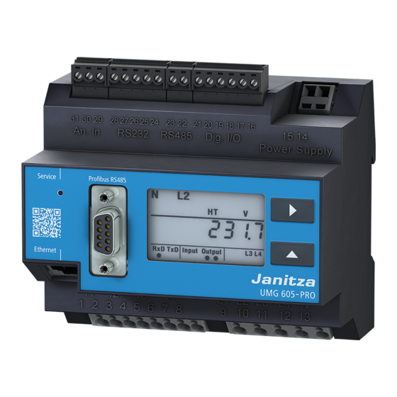
UMG 605-PRO www.janitza.de 4. 6 Product overview Fig. Front view of UMG605-PRO RS232 interface Temperature measurement input Hidden service button Profi bus interface Ethernet interface Current measurement inputs I1 to I4 RS485 interface Digital inputs / outputs Supply voltage Button 1... -
Page 15: Installation Location
UMG 605-PRO www.janitza.de 4. 7 Installation location The device can be installed in switching cabinets or in small installation distributors in accordance with DIN 43880 It is assembled on a 35 mm mounting rail in accordance with DIN EN 60715. It can be installed in any position. -
Page 16: Network Systems
UMG 605-PRO www.janitza.de Network systems Suitable network systems and maximum rated voltages (DIN EN 61010-1/A1): Three-phase four- Three-phase four- Three-phase three- Three-phase three- conductor systems conductor systems conductor systems conductor systems with earthed neutral with non-earthed neutral not earthed with earthed phase... -
Page 17: Three-Phase 4-Conductor Systems
UMG 605-PRO www.janitza.de 5. 1 Three-phase 4-conductor systems 5. 2 Three-phase 3-conductor systems The device can be used in three-phase The device can be used in non-earthed three- 4-conductor systems (TN, TT networks) phase 3-conductor systems (IT network). (50 Hz, 60 Hz) with an earthed neutral conductor. -
Page 18: Rated Voltages
UMG 605-PRO www.janitza.de 5. 3 Rated voltages The following illustrations show lists of networks and the corresponding rated network voltages in which the device can be 115V used. 120V 127V 200V 230V 240V 66 V / 115 V 260V 120 V / 208 V... - Page 19 UMG 605-PRO www.janitza.de...
-
Page 20: Installation
UMG 605-PRO www.janitza.de Installation 6. 1 Disconnectors Damage to property During building installation, provide a suitable due to not observing CAUTION! disconnector in order to disconnect the connection conditions the device from the current and voltage. Failure to observe the connection conditions can damage or destroy your device. -
Page 21: Measured Voltage
UMG 605-PRO www.janitza.de 6. 3 Measured voltage The device is designed to measure AC voltage in 300 V networks, in which overvoltages of category III can occur. The device can only determine measured values if measured voltage of >10 Veff is present on at least one voltage measurement input. -
Page 22: Current Measurement
UMG 605-PRO www.janitza.de 6. 5 Current measurement Risk of injury due The device: to electric voltage WARNING! • is intended for connecting current on current transformers! transformers with secondary currents On current transformers that are operated of ../1 A and ../5 A. -
Page 23: Ammeter
UMG 605-PRO www.janitza.de 6. 5. 1 Ammeter 6. 5. 2 Total current measurement If you wish to measure the current not only For a summation measurement via with the UMG but rather with an ammeter two current transformers, first set their too, connect the ammeter to the UMG total transformation ratio on the device. -
Page 24: Connection Variants
UMG 605-PRO www.janitza.de 6. 6 Connection variants 6. 6. 1 Baseline measurement, inputs 1-3 Four-conductor connection S1 S2 S1 S2 S1 S2 S1 S2 S1 S2 S1 S2 S1 S2 S1 S2 S1 S2 S1 S2 S1 S2 S1 S2... - Page 25 UMG 605-PRO www.janitza.de Three-conductor connection S1 S2 S1 S2 S1 S2 S1 S2 S1 S2 S1 S2 S1 S2 S1 S2 S1 S2 S1 S2 S1 S2 S1 S2 S1 S2 S1 S2 S1 S2 S1 S2 S1 S2 S1 S2...
-
Page 26: Supporting Measurement, Input V4
UMG 605-PRO www.janitza.de 6. 6. 2 Supporting measurement, input V4 Three-conductor connection NOTE! If the baseline measurement (inputs V1-V3) is connected to a three-phase 3-conductor network, the supporting measurement (input V4) can no longer be used as a measurement input. -
Page 27: Temperature Measurement
UMG 605-PRO www.janitza.de 6. 7 Temperature measurement Transmission errors and The device has a temperature measurement damage to property due CAUTION! input that is designed for a maximum total to electrical faults burden of 4 kOhm. If the line is longer than 30 m, there... -
Page 28: Interfaces
UMG 605-PRO www.janitza.de Interfaces Risk of injury due The device has the following interfaces: to electric voltage! WARNING! • RS232 RS232, RS485 and the temperature • RS485 measurement input are not galvanically • Ethernet separated from each other. The Profibus •... -
Page 29: Rs232
UMG 605-PRO www.janitza.de 7. 2 RS232 7. 3 RS485 You can use an RS232 connection cable In the UMG605, the RS485 interface to connect the device to a PC. is designed as a 2-pin plug contact. The achievable distance between two... -
Page 30: Cable Type
UMG 605-PRO www.janitza.de 7. 3. 2 Cable type CAT cables are not suitable for bus wiring. 7. 3. 1 Termination resistors Instead, we recommend the following cable The cable is terminated with resistors (120 Ohm 1/4 W) at the beginning and at the end of a segment. -
Page 31: Bus Structure
UMG 605-PRO www.janitza.de 7. 4 Bus structure • All devices are connected in a bus • It is recommended that the master structure (line). be placed at the end of a segment. • Up to 32 participants can be connected •... -
Page 32: Profibus
Phoenix. If there are no subsequent devices in the line, the bus wiring must be terminated You can order this from us using Janitza item with a resistor (switch to ON). With the switch number 13.10.539. set to ON, terminals 2A and 2B are switched off for further continuing bus wiring. - Page 33 UMG 605-PRO www.janitza.de...
-
Page 34: Digital Inputs And Outputs
UMG 605-PRO www.janitza.de Digital inputs and outputs 8. 1 Digital inputs Transmission errors and The device has 2 digital inputs to which you damage to property due CAUTION! can connect one signal generator each. to electrical faults If the line is longer than 30 m, there is... -
Page 35: S0 Pulse Input
UMG 605-PRO www.janitza.de 8. 2 S0 pulse input You can also connect S0 pulse transducers per DIN EN62053-31 to each UMG 605-PRO with inputs for 24 V. S0 pulse transducer 1.5k You only require external auxiliary voltage of 20 to 28V DC and an external 1.5 kOhm resistor each. -
Page 36: Digital Outputs
UMG 605-PRO www.janitza.de 8. 3 Digital outputs Transmission errors The device has 2 transistor switching and damage to property CAUTION! outputs that are galvanically separated from due to electrical faults the analysis electronics using opto couplers. If the line is longer than 30 m, there... - Page 37 UMG 605-PRO www.janitza.de...
-
Page 38: Commissioning
UMG 605-PRO www.janitza.de Commissioning Before commissioning, clear any content 9. 3 Connecting the measured voltage that may be present on the power meters, After connecting the measured voltages, min./max. values or recordings due the measured values displayed by to the production process. -
Page 39: Applying The Measured Current
UMG 605-PRO www.janitza.de 9. 5 Applying the measured current 9. 6 Checking the power measurement The device: Short-circuit all current transformer outputs • is intended for connecting current except for one and check the displayed transformers with secondary currents power outputs. -
Page 40: Operation
Fig. Display example for rotation fi eld and frequency. NOTE! You can reconfi gure the functions of the buttons and the selection Fig. Front view of UMG 605 -PRO control element of the values to be displayed using the GridVis® software as a Jasic program. (see www.janitza.de) -
Page 41: Programming Mode
1 second, the device returns to NOTE! display mode. If you no longer remember your password, you can only change it using the GridVis® software. (see www.janitza.de) Address Content Content Fig. Display example for "Programming mode", address 000 with a content of 5,000. -
Page 42: Configuration
UMG 605-PRO www.janitza.de Configuration 11. 1 Measurement 11. 1. 2 Supporting measurement The device has 4 measurement channels for voltage (measurement channel 4) measurement (V1 - V4 against Vref) and 4 measurement The supporting measurement only uses channels for current measurement (I1 to I4). -
Page 43: Voltage Transformer Ratio
UMG 605-PRO www.janitza.de 11. 3 Voltage transformer ratio 11. 2 Current transformer ratio You can use addresses 002 and 003 to set You can set the current transformer ratio the voltage transformer ratio for the baseline for the baseline measurement using measurement. -
Page 44: Rs232 Configuration
UMG 605-PRO www.janitza.de 11. 4 RS232 configuration 11. 5 RS485 configuration The following data must be programmed The following data must be programmed to operate the RS232 interface: to operate the RS485 interface: • baud rate, • device address, • operating mode. -
Page 45: Ethernet Configuration
UMG 605-PRO www.janitza.de Address Settings 11. 6 Ethernet configuration Static IP address DHCP mode 0 = static IP In simple networks with no DHCP serv- 1 = BootP er, the network address must be set right 2 = DHCP client on the device itself. -
Page 46: Profibus Configuration
The device master file for your device is called “u6050c2d.GSD” and is available To request a Profibus profile, write the profile on the Janitza homepage. number to the first byte of the PLC's output range. All system variables and global variables... -
Page 47: Pre-Set Profiles
UMG 605-PRO www.janitza.de 11. 7. 3 Pre-set profiles Profibus profile number 0 Byte index Value type Value format Scaling Voltage L1-N Float Voltage L2-N Float Voltage L3-N Float Voltage L4-N Float Voltage L2-L1 Float Voltage L3-L2 Float Voltage L1-L3 Float... - Page 48 UMG 605-PRO www.janitza.de Profibus profile number 1 Byte index Value type Value format Scaling Voltage L1-N Float Voltage L2-N Float Voltage L3-N Float Voltage L2-L1 Float Voltage L3-L2 Float Voltage L1-L3 Float Current L1 Float Current L2 Float Current L3...
- Page 49 UMG 605-PRO www.janitza.de Profibus profile number 2 Byte index Value type Value format Scaling Total active energy L1-L3 Float Rel. Total active energy L1-L3 Float Deliv. Total active energy L1-L3 Float Total reactive energy L1-L3 Float Ind. Total reactive energy L1-L3 Float Total cap.
-
Page 50: Recording Configuration
UMG 605-PRO www.janitza.de 11. 8 Recording configuration Recording 2 2 recordings are pre-configured in the device’s factory default setting. The following measured values are recorded with the time base of 1 hour: Recordings are adjusted and expanded using the GridVis® software. - Page 51 UMG 605-PRO www.janitza.de...
-
Page 52: System Information
UMG 605-PRO www.janitza.de System information 12. 1 Measurement range exceeded 12. 4 Serial number If the measurement range is exceeded, it is displayed as long as this persists and cannot be acknowledged. The measurement range is exceeded if at least one of the four voltage or current measurement inputs is outside its specified metering range. - Page 53 UMG 605-PRO www.janitza.de...
-
Page 54: Device Homepage
UMG 605-PRO www.janitza.de Device homepage Your measurement device has an integrated You can do the following here without first web server, which has a separate homepage. installing any software: You can use this device home page to • call historical and current measured access your measurement device from any values. -
Page 55: Measured Values
UMG 605-PRO www.janitza.de 13. 1 Measured values You can use the measured values menu item to call simple and detailed views of the measured values, and to display individual measured values. The following menu items are available: • Short overview •... -
Page 56: Detailed Measured Values
UMG 605-PRO www.janitza.de 13. 1. 2 Detailed measured values In the overview, you can call extensive information on the following points: • Voltage • Current • Power • Harmonic oscillations • Energy • Peripheral devices (digital inputs/outputs, temperature measurements) Fig. Detailed overview of measured values... -
Page 57: Diagrams
UMG 605-PRO www.janitza.de 13. 1. 3 Diagrams You can use the “Diagrams” item to access the measured values monitor. The measured values monitor is a configurable display of current and historical measured values with automatic scaling. In order to display a graphic of the measured values, drag the required values from the list on the left edge of the screen into the field in the middle of the screen. -
Page 58: Transients
UMG 605-PRO www.janitza.de 13. 1. 5 Transients The “Transients” area provides a graphic illustration of transients within a date list. Transient voltages: • are fast impulse transient effects in electrical networks. • are unpredictable from a time perspective and have a limited duration. -
Page 59: Power Quality
UMG 605-PRO www.janitza.de 13. 2 Power quality The “Power quality” section (PQ) provides you with the option of calling the PQ status in a clear way according to common standards. Here, you have access to permanent power quality monitoring in accordance with: •... -
Page 60: Apps
The push service is an example of an app installed in the factory. The push service sends measured values directly from the device to a cloud or portal solution chosen by you- such as the Janitza Energy Portal Fig. Push Service... -
Page 61: Information
You can use the device information menu item to obtain all information and settings that you can change on the device. 13. 4. 2 Downloads You can use the downloads item to access the download area on the Janitza homepage. You can download catalogues and user manuals from here. 13. 4. 3 Display The display item provides you with the display of your device, which corresponds to the real display. -
Page 62: Service And Maintenance
UMG 605-PRO www.janitza.de Service and maintenance The device underwent various safety checks 14. 5 Battery before delivery and is marked with a seal. The internal clock is fed from the supply If a device is open, the safety checks must voltage. - Page 63 UMG 605-PRO www.janitza.de...
-
Page 64: Procedure In The Event Of Faults
UMG 605-PRO www.janitza.de Procedure in the event of faults Possible fault Cause Remedy No display External fuse for the power Replace fuses. supply voltage has tripped. Device defective. Send the device to the manufacturer for repair. No current display Measured voltage is Connect the measured voltage. - Page 65 UMG 605-PRO www.janitza.de Possible fault Cause Remedy “Error CF” The calibration data could not Send the device to on the display be read. the manufacturer for inspection and testing along with an accurate fault description. Active power, At least one current transformer...
-
Page 66: Technical Data
UMG 605-PRO www.janitza.de Technical data 16. 1 General Net weight 350 g Device dimensions Approx. l=107.5 mm, w=90 mm, h=82 mm (per DIN 43871:1992) Housing flammability rating UL 94V-0 Installation position Fastening/assembly 35 mm DIN rail (per IEC/EN60999-1, DIN EN 50022) -
Page 67: Supply Voltage
UMG 605-PRO www.janitza.de 16. 4 Supply voltage The supply voltage must be connected through a UL/IEC approved fuse (6A char. B) to the device. 230 V option: • Nominal range 95 V to 240 V (50/60Hz) / DC 135 V to 340 V •... -
Page 68: Digital Inputs And Outputs
UMG 605-PRO www.janitza.de 16. 6 Digital inputs and outputs Digital inputs (Pulse input S0) Maximum counter frequency 20 Hz Switching input Input signal present 18 V to 28 V DC (typical 4 mA) Input signal not present 0 to 5 V DC, current less than 0.5 mA... -
Page 69: Temperature Measurement Input
UMG 605-PRO www.janitza.de 16. 7 Temperature measurement input Temperature measurement input Update time approx. 200 ms Connectable sensors PT100, PT1000, KTY83, KTY84 Total burden (sensor + cable) max. 4 kOhm Cable length up to 30 m unshielded, from 30 m shielded... -
Page 70: Interfaces
UMG 605-PRO www.janitza.de 16. 8 Interfaces RS232 interface Connection 5-pin screw-type terminals Protocol Modbus RTU/slave Transmission rate 9.6 kbps, 19.2 kbps, 38.4 kbps, 57.6 kbps, 115.2 kbps RS485 interface Connection 2-pin screw-type terminals Protocol Modbus RTU/slave, Modbus RTU/master Transmission rate 9.6 kbps, 19.2 kbps, 38.4 kbps, 57.6 kbps,... -
Page 71: Voltage Measurement Inputs
UMG 605-PRO www.janitza.de 16. 9 Voltage measurement inputs Three-phase 4-conductor systems (L-N/L-L) max. 277 V / 480 V Three-phase 3-conductor systems (L-L) max. 480 V Resolution 0.01 V Crest factor 2 (related to 480 Vrms) Overvoltage category 300 V CAT III... -
Page 72: Function Parameters
UMG 605-PRO www.janitza.de 16. 11 Function parameters 16. 11. 1 Measurement in the frequency range 50/60 Hz Measurement via current transformer ../5 A Function Symbol Precision class Metering range Display range Total active power (IEC61557-12) 0 to 15.3kW 0 W to 9999 GW... -
Page 73: Measurement In The Frequency Range Of 15 To 440 Hz
UMG 605-PRO www.janitza.de 16. 11. 2 Measurement in the frequency range of 15 to 440 Hz Measurement via current transformer ../5 A Function Symbol Precision class Metering range Display range Total active power (IEC61557-12) 0 to 15.3kW 0 W to 9999 GW... -
Page 74: Specifications Per Iec 61000-4-30 Class S
UMG 605-PRO www.janitza.de 16. 12 Specifications per IEC 61000-4-30 class S Characteristic Uncertainty Metering range Frequency ± 50 mHz 42.5 Hz – 57.5 Hz, 51 Hz – 69 Hz Supply voltage level ± 0.5% of Udin 20% – 120% of Udin Flicker ±... - Page 75 UMG 605-PRO www.janitza.de...
-
Page 76: Parameter List
UMG 605-PRO www.janitza.de Parameter list Address Designation Setting range Unit Default Current transformer, primary, L1 to L4 0 to 1000000 Current transformer, secondary, 1 to 5 L1 to L4 Voltage transformer, primary, L1 to L4 0 to 1000000 Voltage transformer, secondary,... - Page 77 UMG 605-PRO www.janitza.de Address Designation Setting range Unit Default Collect TFTP configuration file 0 to 9999 automatically 0 = deactivated x = file number TFTP error handling 0 to 1 0 = in the event of an error, the configuration menu is shown on the display.
- Page 78 UMG 605-PRO www.janitza.de Address Designation Setting range Unit Default Device address, Modbus/Profibus 1 to 255 Baud rate, RS232 0 to 4 0 = 9600Bit/s 1 = 19200Bit/s 2 = 38400Bit/s 3 = 57600Bit/s 4 =115200Bit/s Baud rate, RS485 0 to 5...
- Page 79 UMG 605-PRO www.janitza.de Address Designation Setting range Unit Default 1 to 31 Month 1 to 12 Year 1 to 9999 xxxx Hour 0 to 23 Minute 0 to 59 Second 0 to 59 Copy date and time 0, 1 1 = copy set data...
-
Page 80: Measured Value Indications
UMG 605-PRO www.janitza.de Measured value indications You can use buttons 1 and 2 on the display to display the following measured values in the factory default setting. The measured value designations used are abbreviated and have the following meanings: • Active power = active power, consumption •... - Page 81 UMG 605-PRO www.janitza.de...
-
Page 82: Dimension Diagrams
UMG 605-PRO www.janitza.de Dimension diagrams 19. 1 Front view Fig. Front view of UMG 605-PRO with installation dimensions... -
Page 83: Side View
UMG 605-PRO www.janitza.de 19. 2 Side view Fig. Schematic side view of UMG 605-PRO with installation dimensions... -
Page 84: Connection Example
UMG 605-PRO www.janitza.de Connection example An. In RS232 RS485 Dig. I/O Versorgungs- spannung Auxiliary Supply Power Analyser UMG 605-PRO Strommessung Spannungsmessung Current measurement Voltage measurement Fig. Connection example for UMG 605-PRO... - Page 85 UMG 605-PRO www.janitza.de...
-
Page 86: Short Introduction (Setting Primary Current)
UMG 605-PRO www.janitza.de Short introduction (setting primary current) You have three identical current transformers with a current transformer ratio of 200 A / 5 A. You want to program the primary current of 200 A. To do this, you must enter the value 200 for the primary current in address 000. - Page 87 UMG 605-PRO www.janitza.de...
Need help?
Do you have a question about the UMG 605 PRO and is the answer not in the manual?
Questions and answers