Table of Contents
Advertisement
Quick Links
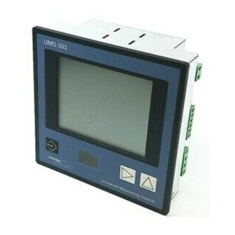
Universal Measuring Device
Operating instructions
Mean value
Displayed phase,
- Outer conductor against N,
- Phase to phase,
- Sum measurement.
Peak values
Lowest values
Mark for the selected ring
buffer values
Consumption
Delivery
Key 1
UMG 503
Current transformers
Harmonic number/Tariff
number
Voltage transformer
Device address
Indication of operation
mode
Key 3
Key 2
Janitza electronics GmbH
Vor dem Polstück 1
D-35633 Lahnau
Support Tel. (0 64 41) 9642-22
Fax (0 64 41) 9642-30
e-mail: info@janitza.de
Internet: http://www.janitza.de
Advertisement
Table of Contents

Subscribe to Our Youtube Channel
Related Manuals for janitza UMG 503


Summary of Contents for janitza UMG 503
-
Page 1: Operating Instructions
Universal Measuring Device UMG 503 Operating instructions Current transformers Harmonic number/Tariff number Voltage transformer Mean value Device address Displayed phase, - Outer conductor against N, - Phase to phase, - Sum measurement. Peak values Lowest values Mark for the selected ring... - Page 2 All rights reserved. No part of this manual may be reproduced or duplicated without the written permission of the author. Any contraventions are punishable and will be prosecuted with all legal means. No liability can be taken for the faultless condition of the manual or damage caused by the use of it.
- Page 3 = Key 1 = Key 2 = Key 3 = Maximum or consumption = Minimum or supply Page 3...
-
Page 4: Table Of Contents
Table of contents Configuration Meaning of the symbols Configuration data Generals Konfigurationsdaten Receipt control Current transformer Hints for usage Voltage transformer Hints for maintenance RS485 interface (Option) Repairing and calibration Transmission protocol RS485 Face plate Terminal resistance Battery RS232 interface (Option) Waste management Transmission protocols RS232 Service... -
Page 5: Table
Hardware Modbus RTU Functions Transmission mode Configure measured value indications Transmission parameters Memory Realized functions Configuration of UMG 503 Data formats Create GSD file PROFIBUS DP (Option) Configuration of UMG 503 WAGO I/O SYSTEM Profibus DP V0 Installation instructions Profibus DP M1... -
Page 6: Meaning Of The Symbols
Meaning of the symbols Warning of dangerous electrical voltage. This symbol is supposed to warn you about possible dangers, which can occur during mounting, putting into service and usage. Protective wire connection Issue note 04.11.1998 First edition. 26.11.1998 Completions. 09.12.1998 Page 22 „password=3846“, page 31 „Gvarh“, page 35 „housing depth“... -
Page 7: Generals
Generals Hints for usage This device may be put into service and used by qualified Receipt control personnel according to the safety regulations and In order to ensure a perfect and safe use of the device, a instructions only. Please mind the additional legal and proper transport, expert storage, erection and mounting safety regulations for the respective application. -
Page 8: Hints For Maintenance
Waste management The UMG 503 can be disposed as electronical waste according to the legal regulations and recycled. Please note, that the input Lithium battery must be disposed separately. -
Page 9: Product Description
Functional description Intended use The electronical three phase measurement system The UMG 503 is suited for fix mounting and the measu- determines and digitalizes the effective values of voltages rement of voltage, current, harmonics (2nd to 20th), and currents in 50/60 Hz networks. -
Page 10: Putting Into Service
The input of the auxiliary voltage (terminals 14, 15) of All devices are connected in bus structure (line). In one the UMG 503 is suitable for rated voltages up to 300VAC segment up to 32 participants can be connected. At the against ground (PE). - Page 11 Connection example 2 Connection example 2a Four wire measurement with three current transformers Four wire measurement with three current transformers Connection example 3 Connection example 3a Four wire measurement with two current transformers = Key 1 = Key 2 = Key 3 = Maximum or consumption = Minimum or supply Page 11...
- Page 12 Connection example 5 Connection example 6 Three wire measurement with three voltage transformers and Three wire measurement with two voltage transformers and three current transformers three current transformers. (Option "three wire measurement" required) Connection example 8 Connection example 7 Three wire measurement with two voltage transformers and Three wire measurement with three voltage transformers and two current transformers.
- Page 13 UMG503 UMG503 Hilfs- Hilfs- spannung spannung Auxiliary Messung Auxiliary Messung Voltage Mesurement Voltage Mesurement L/L 80 .. 870V AC L/L 80 .. 870V AC L/PEN 50 .. 500V AC 0,005 .. 5A L/PEN 50 .. 500V AC 0,005 .. 5A 27 26 25 24 23 22 21 20 19 14 15 27 26 25 24 23 22 21 20 19...
-
Page 14: Putting Into Service
Putting into service The device should be put into service as follows: - Install the device. - Connect auxiliary voltage Uh. The size of the auxiliary voltage to be connected must be according to the details on type plate. The input of the auxiliary voltage (terminal 14, 15) of UMG503 is suitable for rated voltage up to 300VAC against ground (PE). -
Page 15: Removal Of Errors
Removal of errors Faults Possible reason Remedy Indication dark External prefuse has released. Replace prefuse. Internal prefuse has released. The fuse cannot be changed by the user. Please send the device back to the manufacturing works Contrast setting too dark. Change contrast settings in configuration menu. - Page 16 Faults Possible reason Remedy Real power too small / Current transformer factor Read current transformer ratio on current transformer too big programmed incorrectly. and program correctly. Current path is assigned Check and correct connection. to the wrong voltage path. Current on measuring input Install bigger or smaller current transformer.
-
Page 17: Usage
Usage Main menu After a net return the device always starts with the first Keys programmed measured value indication. With key 1 you The UMG503 is operated using the three keys within the change over between front plate. the measured value indication, = Key 1 the SELECT mode, = Key 2... -
Page 18: Measured Value Indication
UMG503, they can be selected in the software PSW basic, which belongs to the contents of delivery, and transmitted via serial interface to the UMG 503. After a net return the device always starts with the first programmed measured value indication. - Page 19 Measured value display (Manufacturer's settings) Mean value voltage L1-N Max. value voltage L1-N Min. value voltage L1-N Meas. val. voltage L1-N Meas. val. voltage L2-N Mean value voltage L2-N Max. value voltage L2-N Min. value voltage L2-N Meas. val. voltage L3-N Mean value voltage L3-N Max.
- Page 20 Meas. value frequency L1 Mean value frequency L1 Max. value frequency L1 Min. value frequency L1 Mean value frequency L2 Max. value frequency L2 Min. value frequency L2 Meas. value frequency L2 Meas. value frequency L3 Mean value frequency L3 Max.
- Page 21 Mean value harmonic I L1 Max. value harmonic I L1 Mean value harmonic I L2 Max. value harmonic I L2 Mean value harmonic I L3 Max. value harmonic I L3 Mean value harmonic U L1 Max. value harmonic U L1 Mean value harmonic.
-
Page 22: Calling Up Additional Information
Calling up additional information Mean values Additional information can be called up for the most For each measured value, except work, a mean value is indicated measured values: calculated. The averaging time is programmable. Only Date and time for the highest and lowest values. mean values can be marked for storage within the ring Averaging times for the mean values. -
Page 23: Minimum And Maximum Values
Minimum and maximum values For each minimum and maximum value, the first time of existance is saved with date and time. To call up, for Scroll to the display of example, the maximum current value in L2, please current using key 3. proceed like mentioned on the right. -
Page 24: Energy Determination
Energy determination Starting time and running time are saved for the follo- The interrogation, for reactive energy ind (T10) for wing real and reactive energy: instance, can be carried out as follows: Real energy without reverse running stop Real energy supply Press key 1 for about 2 seconds and you return to the first Real energy consumption (T00) measured value window of the measured value indicati-... -
Page 25: Real Power Emax
For the most measured values a mean value is build over All EMAX-monthly-peak values are saved for all tariffs the last passed period of time within the UMG 503 each each month. The old EMAX-monthly-peak values are second. This passed period of time is the programmable overwritten at the beginning of a new year. -
Page 26: Reset Of The Measuring Period
Reset of the measuring period The reset of the measuring period deletes real power Reset of the measuring period by keyboard EMAX and starts a new period. With key 3 you scroll to If no external reset is carried out within the programmed the indication of real period, the reset is carried out by the internal clock. -
Page 27: Current Meas. Without Measuring Voltage
The net frequency is detected from the measuring voltage The UMG503 measures the fundamental of voltage in within the UMG 503. From the net frequency, the scan- the range of 45 to 65 Hz. The calculated harmonics of ning frequency for current and voltage inputs is voltage and current apply to this fundamental. -
Page 28: Programming
Byte7/8 with e.g. 1 and rewrite the changed control word to address 5000. Attention! Changing the control Byte incorrectly can lead to malfunctions of the UMG 503. Page 28 = Maximum or consumption = Minimum or supply. = Key 1... -
Page 29: Delete Highest And Lowest Values
Delete highest and lowest values Delete all minimum and max. values Highest values are marked with an arrow upwards, the lowest with an arrow downwards. If you want to delete all maximum values with Text flashing key 1, the indication "ALL"... -
Page 30: Delete Min. And Max. Values Separately
Delete min. and max. values separately If you are in the menu PRG and you would like to delete Pressing key 1 again, the the highest voltage values only, please proceed as follows: highest value in phase L2 is indicated. If this highest value Change to the measu- red value indication... -
Page 31: Ring Buffer
Ring buffer Select mean values If you are in menu PRG and would like to save the mean For the most measured values a mean value is calculated value of voltage L2 within the ring buffer, please proceed (please see table "Measured and calculated values"). as follows: These mean values can be selected for storage in the ring buffer. -
Page 32: Averaging Time
U1, U2, U3, I1, I2, I3, P1, P2, P3 Memory The memory of the UMG 503 is split into three areas: If the averaging time, for example, for voltage L2 should The event memory, the peak and lowest value storage be changed to 5 seconds, please proceed as follows: and the ring buffer. -
Page 33: Period Of Storage
If only 38 seconds are indicated for the period of storage, it cannot be granted any more, that the selected values Lowest values are saved in the UMG 503. To enlarge the period of storage, you can remove some measured values with With key 2 the selec- large periods or increase little periods of storage. -
Page 34: Ring Buffer Data Format
Changeover ring buffer Ring buffer data format The changeover from compressed to uncompressed Data sets can be saved in compressed or uncompressed storage of data is carried out via the serial interface. If form. With the presettings, the data are saved com- the Modbus RTU protocol is used, please use the pressed. - Page 35 Read data sets Example 1: Read the last saved data set. The reading of data sets is controlled by the following Read adress 19008 (Index 235). The ring buffer addresses: pointer (0000) is set to the last data set in ring buffer. Read 12 Bytes from address 19006 (Index 234).
-
Page 36: Configuration
Configuration In configuration menu CONF the required settings are To jump from a measured value indication, in this example noted for operating the UMG503 (see also "Table of the indication of voltage, to the menu CONF, please configuration data"). When the device is delivered, these proceed as follows: settings are not protected and can be changed. -
Page 37: Configuration Data
Configuration data Description Indication Setting range Settings Current transformer, primary 1A .. 999,9MA "5000"A Current transformer, secondary 1A .. 5A " 5" A Voltage transformer, primary 100V.. 99,99kV " 400" V Voltage transformer, secondary 100V .. 500V " 400" V Serial interfaces RS485, RS232, Infrared RS485... -
Page 38: Konfigurationsdaten
Konfigurationsdaten Description Indication Setting range Settings Tariff times Work 0x = Real work, consumption "00" 1x = Reactive work, capacitive 2x = Reactive work, inductive x = Tariff number 0 .. 4 Time number "P. 0" 0 .. 9 " 0" Week day "17.xx d.h."... -
Page 39: Current Transformer
Current transformer Voltage transformer The ratio of the current transformer is set in configurati- The ratio of the voltage transformer is set in configurati- on menu CONF . The secondary current can either be set on menu CONF. The secondary voltage can be set in the to ../1A or ../5A. -
Page 40: Rs485 Interface (Option)
The RS232 interface is suited for transmission of data over a distance of 1200 m. Up to 31 UMG503 and a over a distance of 15m. The UMG 503 can be connected master (PC or SPS) can be connected. directly via this interface to the COM-port of PC or an As PCs usually only have a RS232 interface, a suitable external analogue modem. -
Page 41: Device Address
If several devices are connected via the RS485 interface, a master device (PC, PLC) can distinguish them by the device address only. Therefore each UMG 503 must have another device address. Device addresses can be given from 0 to 255. -
Page 42: Data Recording
Data recording Select The memory of UMG 503 is devided into three areas: In menu CONF scroll The event memory, the t o d i s p l ay o f d a t a peak and lowest value recording "dAtA". -
Page 43: Limits
Digital output clamp DAK6 = Limit 2C DAK4 DAK5 The connection of the UMG 503 to the bus coupling can DAK6 be carried out via the RS232 or RS485 interface. Both devices, UMG503 and bus coupling, must have the same = Relay output(internal) interface. -
Page 44: Assign Limits
Assign limits Example: Sum real power limit number 2B In menu CONF you Limit group Limit=100kW leaf to the indication of the desired limit group Assigned measured using key 3. value= Sum real power. The limit number here is indicated as 1A. Switched at exceeding. -
Page 45: Three Wire Measurement (Option)
Three wire measurement (Option) The UMG503 is suited for measurement in networks with or without neutral conductor. Networks with a neu- tral conductor are called four wire networks, without neutral conductor are called three wire networks. The option "three wire measurement" is needed for the connection examples 5 and 6. -
Page 46: Net Frequency
In the indication, the If the current should be measured without measuring text EDIT appears. voltage, the net frequency should be set at UMG 503. Using key 3, you can EDIT CONF The determination of the scanning frequency can either change over between be done automatically or programmed. -
Page 47: Measured Value Rotation
Measured value rotation Program changing times Select All measured values are calculated two times per second Please scroll to display "changing time Pic" in menu and can be displayed. CONF using key 3. Normally the selection Confirm selection with a n d d i s p l ay i n g o f key 1. -
Page 48: Program Measured Value Selection
Program measured value selection Select Please scroll to display "changing time Pic" in menu CONF using key Confirm selection with key 1. The text EDIT appears. The set changing time is indicated and flashes. EDIT CONF In this example, a chan- ging time of 0 seconds is indicated, which means the measured value rotation is not active. -
Page 49: Analogue Output
The external analogue outputs are controlled via a bus coupling and analogue output clamps of the company WAGO. The connection of the UMG 503 to the bus coupling is carried out via the RS232 or RS485 interface. internal analogue output Both devices, UMG503 and bus coupling, must be con- nected to each other via the same interface. - Page 50 Grounding strip Diagr.: Connection example for 2 UMG503 with analogue outputs to a PLC-analogue input module. Page 50 = Maximum or consumption = Minimum or supply. = Key 1 = Key 2 = Key 3...
-
Page 51: External Analogue Outputs
External analogue outputs are indicated with the numbers The external analogue outputs are controlled via a bus 01 up to 06 in the UMG 503. The numbers correspond to coupling and analogue output clamps of the company the sequence of the analogue output clamps connected to WAGO. - Page 52 The output range of the internal analogue output of the UMG 503 can programmed to 0 .. 20mA or 4 .. 20mA. In The text "AnLo" flas- delivery condition, the analogue output is preset to 4 ..
- Page 53 Example: Sum real power The external analogue outputs can only be indicated and On the internal analogue output of the UMG 503 the sum programmed, when the protocol "06" (Modbus RTU Ma- of real power shall be given out as a current. As a ster) is set at the UMG 503.
-
Page 54: Pulse Output (Option)
Assign energy Various measured values can be assigned to the pulse Corresponding to the mechanical energy meters, the UMG output of the UMG 503 503 has a pulse output as well. At the pulse output, the Without reverse running stop... -
Page 55: Set Pulse Valency
Example: Pulse valency The pulse valency Iw should be destined for a three The pulses from the UMG 503 can be assigned to certain phase network with connected consumers of maximum work. The energy per pulse is given as pulse valency Iw P=400kW. -
Page 56: Event Memory
If the number of events is changed, the contents of the event memory and ring buffer are deleted. The dimension of the memory for event memory and ring buffer is depending on the RAM of the UMG 503. Memory Event memory... -
Page 57: Internal Auxiliary Input (Option)
UMG 503 or via the auxiliary input. Function oFF 1 2 3 4 If a voltage is connected to the auxiliary input, the clock within the UMG 503 will be set to the next full hour. Reset real power EMAX i e1 e1 Tariff change over... -
Page 58: Programming
Programming The external digital inputs can only be indicated and For devices with the auxiliary voltage of "85 .. 265VAC, programmed, if the protocol "06" (Modbus RTU Master) 120 .. 370VDC" the auxiliary input is activated with an is set at the UMG503. alternating voltage of 85 .. -
Page 59: Tariff Change Over
Tariff change over For energy measurement, which should be carried out in certain periods, four tariffs are available: Changeover time Energy meter T01 .. T04 Real energy consumption and real power Symbol Number Symbol Energy type Number EMAX, T11 .. T14 Reactive energy, inductive and Consump- Real energy T21 .. -
Page 60: Internal Tariff Changeover
The time program can be programmed by PC or directly 3. Here consumed real at UMG 503. work was selected. Assignment of the week days: With key 2 you can sel-... -
Page 61: Clock
Clock Summer-/Wintertime changeover The UMG503 can carry out an automatical summer and Date and time are needed as time information for highest wintertime changeover. The following possibilities are and lowest value and storage of measured values in the available: ring buffer. - No summer and winter time changeover. -
Page 62: Software Release
Software Release LCD contrast The software within the device is improved and expan- The best view for the LCD display is "from below". The ded continuously. Therefore the condition of software is contrast of the LCD display can be adapted by the user. marked by the software release. -
Page 63: Password
Password Clearance password In the various device variants functions are available as Certain functions are protected by a user password. an option. These function expansions can be released in There are three types of passwords: the manufacturing works, when ordering. Clearance password (8-digits) When later a functional expansion shall be released by User password (4-digits) -
Page 64: User Password
User password Master password With the four digit user password the user can protect the The four digit master password is needed for service programmed data and configuration against unintentio- purpose only and it is not announced to the user. nal change. -
Page 65: Transmission Protocols
Transmission protocols Service protocol The service protocol is used for calibration and testing For the connection of the UMG 503 to existing field bus purpose in the manufacturing works only. systems, two transmission protocols are at your disposal: - PROFIBUS DP (Slave) -
Page 66: Modbus Rtu
Measured values (floating point format) months, day, hours, minutes and second in the format Table 1b Measured values (floating point format) "char" = 0..255. The device address of the UMG 503 is Table 2 Energy (floating point format) determined as address = 01. -
Page 67: Profibus Dp (Option)
Configuration of UMG 503 The following requirements and settings are necessary The UMG 503 corresponds to the field bus norm PROFI- for the operation of UMG 503 at Profibus DP: BUS DP, DIN E 19245 part 3 as a slave device. The - A RS485 interface, device is listed by the PROFIBUS user organisation e.V. -
Page 68: Profibus Dp V0
3. The scaling of the measured values depends on the ratios for current and voltage transformer set at UMG 503 and must be read by changing the ratios only. The output and input range can be read out and overwrit- ten by the control words 1 and 2 from PLC. - Page 69 Output range of PLC (32 words=64 Byte) Control word1 In- and outputs bit 0..1 Tariffs 0-3,real work, consumption bit 2..3 Tariffs 0-3, reactive work, inductive bit 4..5 Tariffs 0-3, reactive work, capacitive bit 6 Remote tariff change over bit 7 Synchronization of internal clock, 0 bit 8 Reset real power EMAX, 0...
- Page 70 8002 current and voltage transformer ratios, which are set at Real power, Sum 8024 UMG 503, and must only be read after a change of those ratios Control word 1 = In- and outputs "0000" (Example) Control word 2 = In- and outputs "0000"...
- Page 71 Example: Measured values in foating point format Read measured values The UMG 503 and the PLC are suited for "higher proto- The measured values in floating point format can be col". A current transformer of 200A/5A and a voltage found in table 1. The following addresses can be read in transformer of 400V/400V have been set.
-
Page 72: Create A Gsd File
The binding of the GSD file in a program is carried out by the customer. It is very different from application to application. Instructions for binding in a UMG 503 in a Siemens SPS S7 (CPU 315-2DP) can be downloaded from the internet page "http://www.janitza.de". -
Page 73: Serial Interfaces
Serial interfaces The UMG503 is available with the serial interfaces RS232, RS485 and Infrared. In the basical edition, at least one interface RS485 or RS232 is at your disposal. The interfaces can be used at the same time, even with different protocols. -
Page 74: Tables
Tables Overview Table 1a Measured values, floating point format Table 1b Measured values, floating point format Table 2 Energy, floating point format Table 3a Time information for minimum and maximum values and system time Table 3b Time information for minimum and maximum values and summer/winter changeover Table 4 Averaging time of mean values Table 5... -
Page 75: Table 1A
Table 1a Measured values in floating point format Description Index Address Type Unit Comment (dez) DPV1 DPV0/MODB. Current 1000 meas. val. L1, L2, L3 Voltage N-L 1012 meas. val. L1, L2, L3 Voltage L-L 1024 meas. val. L1-L2, L2-L3, L1-L3 Real power 1036 meas. -
Page 76: Table 1B
Table 1b Measured values in floating point format Description Index Address Type Unit Comment (dez) DPV1 DPV0/MODB. Total harmonic distortion _U Mean value 1390 float[3] L1, L2, L3 Total harmonic distortion _I Mean value 1393 float[3] L1, L2, L3 1396 Partial harmonics _U Minimum value 1400... -
Page 77: Table 2
Table 2 Energy in floating point format Description Index Address Type Unit Comment (dez) DPV1 DPV0/MODB. Real energy, Consumption 220 2000 double[4] Energy, Tariff1, Tariff2, Tariff3, Tariff4 Reactive energy, inductive 221 2010 double[4] varh Energy, Tariff1, Tariff2, Tariff3, Tariff4 Reactive energy, capacitive 222 2020 double[4] varh... -
Page 78: Table 3A
Table 3a Time information for minimum and maximum values and system time Description Index Address(dez) Type Comment DPV1 DPV0/MODB. System time 3000 char System time Current L1, L2, L3 3001 char[2][3] Min. value, Max. value; L1, L2, L3 Voltage N-L 3007 char[2][3] Min. -
Page 79: Table 3B
Table 3b Time information for minimum and maximum values and system time Description Index Address Type Comment (dez) DPV1 DPV0/MODB. free 3205 Partial harmonics _U Minimum value 3210 char[20][3] Partial harmonics 1-20; L1, L2, L3 3211 3265 Partial harmonics _U Minimum value 3270 char[20][3]... - Page 80 To change a byte of the "internal control word", the "internal control word" must be read, and the changed word must be written back to address 5000. Attention! If the bytes with the comment "Only internal use" are changed, this may lead to a faulty operation of UMG 503! r/w = read/write Page 80 = Maximum or consumption = Minimum or supply.
-
Page 81: Table 6A
Table 6a Measured values in integer format Index Address Format Unit Comment Measured values (dez) DPV1 DPV0/MODB. Current 8000 word[3] L1, L2, L3 Voltage 8003 word[3] N-L1, N-L2, N-L3 Voltage 8006 word[3] L1-L2, L2-L3, L1-L3 Real power 8009 word[3] L1, L2, L3 Apparent power 8012 word[3]... -
Page 82: Table 6C
Table 6c Maximum values in integer format Maximum values Index Address Format Unit Comment (dez) Current 8314 word[3] L1, L2, L3 Voltage 8317 word[3] N-L1, N-L2, N-L3 Voltage 8320 word[3] L1-L2, L2-L3, L1-L3 Real power 8323 word[3] L1, L2, L3 Apparent power 8326 word[3]... -
Page 83: Table 7
Table 7 Energy in integer format Energy Index Address Format Unit Comment (dez) Real energy, consumption 9000 long Scale see address 9102 Real energy, supply 9001 long Scale see address 9102 Real energy without rev. running stop 9002 long Scale see address 9102 Reactive energy, capacitive 9003 long... -
Page 84: Table 8
Programmed scale = -1 into integer formats by UMG 503, such as char, int and Which voltage is measured by the UMG 503? word (Table 4). In order not to lose a digit after decimal point, the From the scale table, you can read the factor =/10 for transmitted value is scaled. -
Page 85: Table 9
A remote Bit is assigned to each in- or output, that can be controlled externally. If this remote Bit=0, the in- or output is controlled by the UMG 503 only. If the remote Bit=1, the in- or output is controlled externally. - Page 86 Table 10 EMAX-Peak values Description Address Type Comment (dez) Real power EMAX Peak value 16000 float [Tariff] [Month] Measured value in Watt Date Year 16500 char [Month] The month of the year, in which... 16600 char [Tariff] [Monat] The day of the month, in which the peak value appeared Time Hour...
- Page 87 = Key 1 = Key 2 = Key 3 = Maximum or consumption = Minimum or supply Page 87...
-
Page 88: Pswbasic
- Windows® NT4.0 mit Service-Pack3 Only the contents of the minimum and maximum memo- ry can be read out directly at the UMG 503. The event - Windows® 2000 memory and the ring buffer must be read out by PC. -
Page 89: Configuration Of Umg 503
Configuration of UMG 503 Create GSD file A simple configuration of the UMG 503 can be carried Devices with PROFIBUS protocol need a GSD file. The out directly at the device via the three keys and display. A GSD file is a file which is specific for the device, in... -
Page 90: Wago I/O System
A simple expansion of the inputs and outputs of the Modbus coupling: UMG 503 is possible with the WAGO I/O SYSTEM. The Digital inputs UMG 503 is connected to the bus coupling via an interface 750-400 2-chanel digital input 24V; 3,0ms cable. The Modbus RTU... -
Page 91: Bus Coupling
9600, 19200 750-316 RS232 9600, 19200, 38400 If the UMG 503 is connected to the bus coupling via RS232 interface, a "1 to 1 cable" must be used. Connections via RS485 interface are carried out according to the diagram below. -
Page 92: Indicating Range And Accuracy
Indicating range and accuracy Quantity Indicating range Measuring range for Measuring Scale factor=1 accuracy Voltage 0,0V .. 999,9 MV 50 .. 500 V ±0,2% rng 0,0V .. 999,9 MV 80 .. 870 V ±0,2% rng Current 0,000 .. 9999 A 0,005 .. -
Page 93: Technical Data
Technical Data Ambient conditions Overvoltage class : CATIII Measurement Pollution degree Mode : True (RMS) Operating temperature : -10°C .. +50°C Measuring rate : 2 measurements/sec. Storage temperature : -20°C .. +60°C Actualization humidity class : 15% to 95% Display : 1 time per second (without dew) Analogue output... -
Page 94: Design For Panel Mounting
The grey marked connections are available as options. All dimensions are given in mm. Design for DIN Rail Mounting (Option) Side view Back side Diagr. Feeding wires for a DIN Rail mounted UMG 503 Page 94 = Maximum or consumption = Minimum or supply. = Key 1... -
Page 95: Connection Example
Connection example = Key 1 = Key 2 = Key 3 = Maximum or consumption = Minimum or supply Page 95... -
Page 96: Brief Instructions
Brief instructions Current transformer Select programming menu. Select current transformer. Primary current Select number. Secondary current Change number. Move decimal point. 2 Sek. Save and measured value CONF indication. Votage transformer Select programming menu Confirm selection. Select voltage transformer. Primary voltage Secondary voltage Select number.
Need help?
Do you have a question about the UMG 503 and is the answer not in the manual?
Questions and answers