Advertisement
Quick Links
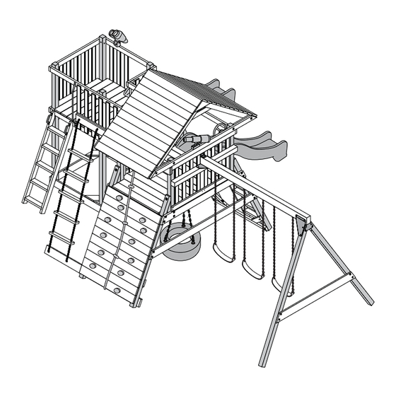
2293-SB
- NOTICE -
This playset product is not intended for public use. It is intended for
residential application and is not warranted for public or commercial use.
STOP!
STOP!
Call Us First!
DO NOT RETURN TO STORE.
For immediate help with assembly or product information
call our toll-free number:
1-866-890-2211
April through October M - F 8:00 AM to 6:00 PM EST
Saturday 8:30 AM to 4:30 PM EST
November through March M - F 8:00 AM to 5:00 PM EST
or email:
customerservice@backyard-play.com
Our staff is ready to provide assistance.
Advertisement

Subscribe to Our Youtube Channel
Related Manuals for Backyard Play Systems ULTRA PLAYSET 4098


Summary of Contents for Backyard Play Systems ULTRA PLAYSET 4098
- Page 1 2293-SB - NOTICE - This playset product is not intended for public use. It is intended for residential application and is not warranted for public or commercial use. STOP! STOP! Call Us First! DO NOT RETURN TO STORE. For immediate help with assembly or product information call our toll-free number: 1-866-890-2211 April through October M - F 8:00 AM to 6:00 PM EST...
- Page 3 2293-SB 12/18/2012 Customer Service Model 4098, Backyard Play Systems 1-866-890-2211 6315 ULTRA PLAYSET 1000 Ternes Monroe, MI 4816 Recommended for Ages 3 to 11 - BEFORE YOU BEGIN - Tools Required First... Adult Assistance required Assistance is necessary to handle, Check with your homeowner’s association before...
- Page 4 (This page intentionally left blank.)
- Page 5 ASSEMBLY SAFETY and HELPFUL HINTS ASSEMBLY SAFETY and HELPFUL HINTS STOP!!! Check all parts and hardware before beginning. If any parts are missing or damaged please circle and call the phone number listed. DO NOT CONTACT THE STORE OR RETURN YOUR PLAYSET ! KEEP THIS INSTALLATION MANUAL FOR FUTURE CARE AND MAINTENANCE REFERENCE.
- Page 6 SAFETY WARNINGS Please read carefully. Observing the following statements and warnings reduces the likelihood of serious or fatal injury. This playset has been designed for use by a maximum of ten occupants at one time having a combined weight of 1,500 pounds. (This weight does not include occupants on the optional monkey bars, glider, or tire swing). This playset is recommended for children (3) through (11) years of age.
- Page 7 MAINTENANCE Periodic maintenance is required to ensure safe enjoyment of your playset and optional accessories. Observing the following procedures reduces the likelihood of serious or fatal injury. Activity on your playset and optional accessories may loosen fasteners. Check all lock nuts, hex and lag bolts, quick clips, spring clips, acorn nuts, wood screws, and swing hangers for tightness and tighten as required.
- Page 8 PLAYGROUND SURFACING MATERIALS SECTION 4 OF THE CONSUMER PRODUCT SAFETY COMMISSION’S OUTDOOR HOME PLAYGROUND SAFETY HANDBOOK Select Protective Surfacing and around your play equipment. The protective surfacing should be applied to a depth that is suitable for the equipment height in accordance with NOTE: Do not install home playground equipment over concrete, asphalt, or any other hard surface.
- Page 9 PLAYSET ORIENTATION *Hint - Throughout this manual references made to the Left Side, the Right Side and the Front of the playset serve as a consistent reminder to help with assembly: LEFT SIDE FRONT SIDE RIGHT SIDE...
- Page 10 IMPORTANT! Use these Assembly Procedure Hints throughout the installation process. 1. All Lag Bolts must have pre-drilled holes. Use a 1/4” drill bit for all 3/8” Lag Bolts. Use a 3/16” drill bit for all 5/16” Lag Bolts. Pre-drilling pilot holes will help prevent Screws and Lag Bolts from breaking and wood from splitting during assembly.
- Page 11 BASE PARTS LIST WOOD SIZE CONVERSION CHART Nominal Board Size Actual Size 1“ x 4”..........3/4” x 3-3/8” .......... 1“ x 6” 3/4” x 5-3/8” 1199-ST 1021-ST 1200-ST 5/4“ x 4”..........1” x 3-1/2” 5/4“ x 6”..........1” x 5-1/2” 2“ x 4”........1-3/8” x 3-3/8” 2“...
- Page 12 Angle Bracket Plate Swing Beam 90 Plate Swing Beam Angled Plate Left Swing Beam Angled Plate Right Square-Hole 2485 2449 Swing Beam Flat Plate 2411 2448 2447 Spring Clip Swing Hanger Plastic Hole-Plug Angled Angle plug 2433 2004 Safety Handle Binoculars Plaque Climbing Rocks - Green...
- Page 13 A C T U A L S I Z E S H O W N 3/8” LAG BOLT WOODSCREWS x90 x63 x8 x5 x240 1-1/4" 1-5/8" 1-3/4" 2" 2-1/2" 3" 3" 3-1/2" 4" 1/4" SAFETY HANDLE HDW. 3/8" FLAT WASHER TRUSS HEAD SCREW 1-1/2"...
- Page 14 A C T U A L S I Z E S H O W N 4-1/2" 5" 5-1/4" 5-1/2" 6" 4" 3/8" 3/8" 3/8" 3/8" 3/8" 3/8" 3-3/4" 3-1/2" 2-1/2" 2" 1-1/2" 1-1/4" 3/8" 3/8" 3/8" 3/8" 3/8" 3/8"...
- Page 15 A C T U A L S I Z E S H O W N 3-3/4" 4-1/2" 6-1/2" 7" 9" 3/8" 3/8" 3/8" 3-1/2" 3/8" 3/8" TORQUE WASHER 3/8" 3/8" 3/8"...
- Page 16 TOWER & BRIDGE PARTS LIST WOOD SIZE CONVERSION CHART Nominal Board Size Actual Size 1“ x 4”..........3/4” x 3-3/8” .......... 1“ x 6” 3/4” x 5-3/8” 1121-ST 1051-ST 2327-ST 5/4“ x 4”..........1” x 3-1/2” 5/4“ x 6”..........1” x 5-1/2” 2“ x 4”........1-3/8” x 3-3/8” 2“...
- Page 17 3/8" HEX HEAD BOLTS #2 SQUARE DRIVE BIT " 1-1/2 " 2-1/2 " " 3-3/4 " 3/8” " 5-1/2 " " " 2-1/2” PAN HEAD " " SCREW " x100 " " 2-1/2 3/8” LAG BOLTS " 2-1/2 " " 1-1/4 "...
- Page 18 SET-UP ORIENTATION BACK SIDE 31'-10" 6' SAFETY AREA SLIDES 19'-10" RIGHT SIDE LEFT SIDE 11'-1" HEIGHT 29'-5" 17'-5" TOWER SWING ROCK WALL 6' SAFETY AREA FRONT SIDE This space intentionally left blank.
- Page 19 FORT PARTS LAYOUT *IMPORTANT! 2310-W 2545-ST 1029-ST Lay Out Corner Posts as shown. 2312-ST LEFT Note 2547-W hole location. FRONT 2547-W IMPORTANT! Install 1001-ST with 1001-ST RIGHT counterbores oriented as shown. FORT CORNER POSTS / FLOOR SUPPORTS LEFT SIDE 2310-W Flat Washer Lock Washer 1001-ST...
- Page 20 FORT CORNER POSTS / FLOOR Outside of Posts 48" they are evenly spaced Make sure corner before installing screws. posts are squared to 2312-ST measurements shown. Center boards between 1029-ST 48" and corner posts. 2545-ST 56-1/2" 56-1/2" 2-1/2" Wood Screws x52 Flush 48"...
- Page 21 FORT ROOF SUPPORTS LEFT SIDE 1199-ST 1-5/8" Wood Lock Screws Washer Flat 1200-ST Align Holes Washer 4" Hex Bolt 1-5/8" Wood Screws Flat Washer Lock Washer 4" Hex Bolt but do not fully tighten. Re-Adjustment will be necessary. RIGHT SIDE FORT SIDE WALLS Keep 56-1/2"...
- Page 22 FORT UPPER ROPE ARM Orient Rope Arm parts 2540-ST as shown. Assemble using 1-3/4" screws, 2" Hex Bolt, Washers and T-Nut. Tighten the screws and the bolt securely. 1-3/4" Wood Screws Flush when assembled. T-Nut 1-3/4" Wood Screw *Note - 2540-ST 1-3/4"...
- Page 23 FORT UPPER ARMS LEFT SIDE Re-adjustment will be neccessary. 4" Hex Bolt 2540-ST Assembled 1009-ST PRE-DRILL 1/4" x 1-1/2" DEEP before installing lag bolts. Lock Washer Flat Washer Flat Washer Lock Washer 3-1/2" Lag Bolt 5" Hex Bolt RIGHT SIDE Flat Washer 3-1/2"...
- Page 24 FORT INSTALL LEGS LEFT SIDE * Note - 5-1/4” Hex Bolt For Safety two people are required to carefully roll fort over. Plastic 5-1/2” Hex Bolt Angled Plug Plastic 5-1/4” Hex Bolt with Angled Plug Lock washer and Flat Washer 5-1/2”...
- Page 25 FORT BOTTOM SUPPORTS DO NOT OVER-TIGHTEN LAG BOLTS SIDE VIEW LEFT SIDE Lag Bolt 1088-ST T-Nut Hex Bolt 3-1/2" Lag Bolt T-Nut 1009-ST PRE-DRILL 1/4" x 1-1/2" DEEP before installing T-Nut lag bolts. 4" Hex Bolt 3-1/2" Lag Bolt Lock Washer T-Nut 4"...
- Page 26 FORT INSTALL LEGS * Note - For Safety two people are required to carefully roll fort over. Remove and re-insert each 5-1/4" Hex Bolt (one at a time) through the holes from the opposite direction - this time using a Lock Washer, Flat Washer and T-Nut Install And Tighten Into T-Nuts At This Time.
- Page 27 FORT STEP LADDER 2-1/2" Wood Screws (x 22) Angled End 2316-ST 1053-ST Flush 2315-ST POSITION LADDER TOP BLOCK 1053-ST AS SHOWN TO LADDER RAIL. 1051-ST Back Back side Front of ladder FORT STEP LADDER Position assembled Step Ladder under Deck End Board and against inner floor support.
- Page 28 FORT STEP LADDER 1053-ST 1-5/8” Screws (x3) 3” Wood 1053-ST Screws Flush Lock Washer T-Nut Position Ladder Top Block beneath Deck End Board. Attach with three 1-5/8” Wood Screws. When installed, front edge of Ladder Flat Top Block (1053-ST) should be flush with 4-1/2”...
- Page 29 FORT SWING BEAM SUPPORT LEFT SIDE 1. Pre drill 3/16" pilot holes through 2568-ST from inside (A). Center drill in counterbore. Flat Washer 2-1/2" Hex Bolt 2568-ST Lock Washer T-Nut 2" Hex Bolt Lock Washer 2. Drill 7/16" through holes through 2568-ST from Flat outside (B).
- Page 30 SWING BEAM How to install Torque Washers Thread Carriage Bolt Make sure Carriage Bolt through Torque Washer square shank is aligned before seating the with square hole in Torque Torque Washer. Tap of Torque Washer by with hammer. of the Torque Washer. tapping into place.
- Page 31 SWING BEAM A - FRAME T-Nut x2 2525-W Rotate 2525-W 180 after installing T-Nuts. SWING BEAM ASSEMBLE 3-3/4" Hex Bolt Lock Washer Flat Washer Pre-installed T-Nuts 2506-ST are underneath.
- Page 32 SWING BEAM HARDWARE 3-1/2" Carriage Bolt 2411 BACK SIDE RIGHT SIDE NOTE: Ensure two to three threads are exposed past Lock Nut. Flat Washer Lock Nut SWING BEAM HARDWARE 2449 DO NOT FULLY TIGHTEN CARRIAGE BOLTS AT THIS TIME 3-3/4" Carriage Bolt Lock Nut Flat Washer NOTE:...
- Page 33 SWING BEAM HARDWARE DO NOT FULLY TIGHTEN 2749-W CARRIAGE BOLTS AT THIS TIME Flat Washer Lock Nut 2448 4-1/2" Carriage Bolt NOTE: You may need to tap bolts with hammer to get through holes. Clean all debris from bolt threads 2447 before installing lock nuts.
- Page 34 SWING BEAM ASSEMBLE Align holes and insert carriage bolt. Repeat where arrows are shown. 3-3/4" Carriage Bolt DO NOT FULLY TIGHTEN CARRIAGE BOLTS AT THIS TIME Flat Washer Lock Nut SWING BEAM ASSEMBLE 6-1/2" Carriage Bolt Torque Washer NOTE: You may need to tap bolts with hammer to get through holes.
- Page 35 SWING BEAM INSTALL Position swing beam assembly resting upon plate and align with holes. 9" Carriage Bolt 6-1/2 Carriage Bolt NOTE: You may need to tap bolts with hammer to get through holes. Clean all debris from bolt threads before installing lock nuts. Torque Washer RIGHT SIDE 2485...
- Page 36 SWING BEAM INSTALL T-Nut Flat Washer Lock Washer 1-1/2" Hex Bolt RIGHT SIDE SWING BEAM INSTALL T-Nut Flat Washer Lock Washer 1-1/2" Hex Bolt RIGHT SIDE...
- Page 37 SWING BEAM ASSEMBLE & LEVEL Level swing beam and tighten all swing beam fasteners. Pre drill 1/4" x 1-1/2" deep hole. Tighten all fasteners 3" Lag Bolt Lock Washer Flat Washer SWING BEAM FINAL ASSEMBLY 2-1/2" Pan Head Screw 1/4 x 1" Fender Washer...
- Page 38 LAY OUT PARTS - ROCK LOCATIONS ROCK WALL 41” 1026-ST centered Place and align parts 1026-ST parallel on ground. *Hint: Number the order of each part (1026-ST) for correct re-orientation, top to bottom. Mark parts on back side or use masking tape. Lay Out all Climbing Rocks (x12) in an attractive and practical fashion (6-GREEN, 6-YELLOW).
- Page 39 ROCK WALL INSTALL T-NUTS Turn all eleven 1026-ST panels over (lay on a soft but firm surface). Pound in 1/4" T-Nuts (in separate bag 2452) at each hole location. 1/4” T-Nut x26 ROCK WALL INSTALL ROCKS 1/4” x 1-1/2” Hex Head Bolts 1/4”...
- Page 40 ROCK WALL INSTALL 1-5/8" 2-1/2" Screws Screws 1026-ST 1/2" Install top rock wall board (1026-ST) Secure rock wall cleat (2548-ST) with middle holes of (1026-ST) top board. Center Upper end of rock wall cleat (2548-ST) 1026-ST) top board. Flush Make sure rock wall cleat ( 2548-ST ) is pulled tightly against back of (1026-ST) top board.
- Page 41 ROCK WALL INSTALL 1-5/8" Screws (x18) LEFT SIDE 1026-ST RIGHT SIDE Continue securing rock wall cleat (2548-ST through middle holes of rock wall boards. Make sure rock wall cleat (2548-ST) is pulled tightly against back rock wall boards. FORT SWING SIDE WALL INSTALL THESE TWO BALUSTERS FIRST.
- Page 42 FORT SWING SIDE WALL RIGHT SIDE INSTALL THESE 1-1/4" Wood Screws 2537-ST TWO BALUSTERS SECOND. Flush Use 2537-ST as a 3-1/4" spacer. Install each 2537-ST Inside View FORT BRIDGE SIDE WALL 1-1/4" Wood LEFT SIDE INSTALL THIS Screws BALUSTER FIRST Inside View 2537-ST Use 2537-ST as a...
- Page 43 ROPE LADDER ASSEMBLE & INSTALL 2540-ST x2 Pre-assembled Step 1 Upper Rope Arm ( 2540-ST ) and tie a double knot. 21-1/2" Step 2 Slide one Ladder Rung ( 1025-ST ) up the Ropes and tie a single knot in each rope. Repeat this step four more times with remaining Ladder Rungs.
- Page 44 CLIMBING ROPE INSTALL 2540-ST Pre-assembled OPTIONAL: Tie several single knots in locations to allow logical hand-grab points. 1088-ST Step 1 of Upper Rope Arm ( 2540-ST ) and tie a double knot on the back side ( Fig. 1) Step 2 Fig.
- Page 45 ROOF RAFTERS 1198-ST Lay out four rafter-halves (1198-ST) as shown. Pound in T-Nuts. ROOF RAFTERS Flush at peak Flush at peak 1198-ST STEP 2 STEP 1 T-Nuts are facing inward.
- Page 46 ROOF ROOF BOARDS Center roof boards on rafters. Ensure equal overhang on both sides; about 7/8". 2569-ST Maintain 43-3/8" dimension between rafters. Flush at peak ROOF ROOF BOARDS 2567-ST Insert panels fully seated. Install all roof boards Flush. REPEAT INSTALLATION OF ROOF BOARDS (2567-ST) ON OPPOSITE SIDE.
- Page 47 ROOF ROOF BOARDS REPEAT INSTALLATION OF ROOF BOARD (2569-ST) ON OPPOSITE SIDE. 2569-ST ROOF TRIM & RAFTER SUPPORT Flush Screws installed from 1202-ST outside. 1-1/4" Wood Screws 1201-ST Screws installed from inside. Flush...
- Page 48 SWINGS INSTALL Clip a Spring Clip at the end of each Swing and Trapeze chain. Then, using the Spring Clips, attach the Swings and Trapeze to the swing brackets on the swing beam, as shown below. 2004 Attach Playset Plaque using One 1"...
- Page 49 STAKES Stakes Flush with TOP. STAKE STAKE STAKE STAKE 1015 STAKE STAKE 2-1/2" Wood Screws (x4) STAKE STAKE STAKE Stakes Flush with SIDES. Pound in Stakes (1015) at 45 degree angle. Make sure all base pieces, uprights and slide It may be necessary to loosen the soil beneath 2-1/2"...
- Page 50 SLIDE SLIDE MOUNT INSTALL 2" Wood Screw 2-3/4" 2312-ST 1051-ST 1051-ST 1" Position slide mount beneath deck end board. Attach with two 2" wood screws as shown. Center Part 1051-ST on deck board. 4-3/4" 14" 15-3/8" 3/4" 3/4"...
- Page 51 SLIDE MEASURE End deck board 1085-ST 1051-ST 3/4" 2312-ST 4" Slide 2442 SLIDE DRILL Drill 1/8" holes at dimples through Slide and 2312-ST into 1051-ST (1 inch deep). 2312-ST Slide...
- Page 52 SLIDE MOUNTING SCREWS 2-1/2" Pan Head Wood Screw 1/4" x 1" Fender Washer 2312-ST SLIDE SURFACING MATERIAL Apply Surfacing Material at recommended depth, or deeper.
- Page 53 SAFETY HANDLES INSTALL The height of the handles is to be determined by the customer - depending on the age of the child, etc. 1/8" Pre-Drill 2405 (Do not drill through.) 1-1/2" Lag Bolts Flat Washer DO NOT OVER-TIGHTEN LAG BOLTS BACK BOTTOM END RAIL GUSSETS INSTALL DO NOT OVER-TIGHTEN LAG BOLTS...
- Page 54 INSTALL ROPE LADDER BOTTOM SUPPORT GUSSETS DO NOT OVER-TIGHTEN LAG BOLTS 4" Lag Bolt Lock Washer Flat Washer 1/4" Pre-Drill x 2" deep. 1/4" Pre-Drill x 2" deep. 1/4" Pre-Drill x 2" deep. 1020-ST 3-1/2" Lag Bolt Flat Washer Lock Washer DO NOT OVER-TIGHTEN LAG BOLTS INSTALL SWING SAFETY BARRIER...
- Page 55 STOP THE TIRE SWING KIT MAY BE INSTALLED NOW. REFER TO THE TIRE SWING INSTALLATION MANUAL. BEGIN TOWER & BRIDGE ASSEMBLY RIGHT SIDE BACK SIDE LEFT SIDE FRONT SIDE...
- Page 56 TOWER FRAME 1 T-NUTS Install T-Nuts BEFORE Eventual parts shown T-Nut x10 assembling Tower. for positioning only (don’t install yet!). T-Nuts should be installed toward the INSIDE of tower legs (2329-W). After installing all T-nuts, lengthwise, as shown. 2329-W IMPORTANT! Orient both parts 2329-W as shown for T-nut installation.
- Page 57 TOWER FRAME 2 T-NUTS Install T-Nuts BEFORE assembling Tower. IMPORTANT! Orient both parts 2329-W as T-Nuts should be installed shown for T-nut installation. Pay close attention to hole toward the INSIDE of locations! tower legs (2329-W). 2329-W After installing all T-nuts, lengthwise, as shown.
- Page 58 TOWER ASSEMBLE 1113-ST Flat Washer Lock Washer 4" Hex Bolt with top of board. TOWER ASSEMBLE Get a helper to steady the Tower Frame during this step. LEFT SIDE Flat Washer Lock Washer 4" Hex Bolt FRONT SIDE...
- Page 59 TOWER ASSEMBLE 1124-ST 1124-ST 3" Wood Screw x4 FRONT SIDE Flush 3-3/4" Hex Bolt x4 Flat Washer Lock Washer TOWER ASSEMBLE LEFT SIDE FRONT SIDE 1115-ST 4" Hex Bolt Flat Washer Lock Washer...
- Page 60 TOWER FRAME 1116-ST 3" Wood Screws x4 FRONT SIDE Flush 17-3/8" BACK SIDE 17-3/8" Flush TOWER DECK Center between 2329-W and 2329-W. BACK SIDE 4-1/2" 2329-W 2-1/4" 2329-W 2328-ST 2-1/2" Wood Screws 2329-W 2329-W FRONT SIDE...
- Page 61 TOWER DECK 2-1/2" Wood Screws 2327-ST FRONT SIDE 1123-ST (spaced evenly) 2327-ST 2328-ST (pre-installed) BACK SIDE BRIDGE FRAME 2084 2336-ST FRONT SIDE Flat Washer Pre-Installed T-Nut Lock Washer 1-1/2" Hex Bolt...
- Page 62 BRIDGE FRAME 1-11/16" From edge of corner post. 1-13/16" Measure and Mark four locations. 1-3/4" LEFT SIDE 1-11/16" From edge of corner post. BRIDGE FRAME 7/16" Pre-Drill through.
- Page 63 BRIDGE FRAME 3-11/16" Mark both locations. 6" From inside of Corner Post. BRIDGE JOIST 1-1/2" Hex Bolt Lock Washer 2084 Flat Washer 1118-ST Flush Flush T-Nut...
- Page 64 BRIDGE JOIST Flush Flush 7/16” Drill Through 7/16" Drill Through T-Nut T-Nut 2336-ST Flat Washer Lock Washer Flat Washer 1-1/2” Hex Bolt Lock Washer 1-1/2" Hex Bolt BRIDGE JOIST Flush Flush 1118-ST T-Nut T-Nut 1-1/2” Hex Bolt Lock Washer Flat Washer 1-1/2"...
- Page 65 BRIDGE ATTACH Flat Washer T-Nut Lock Washer 2-1/2" Hex Bolt T-Nut 2334-ST T-Nut BRIDGE DECK Flush to uprights 2-1/2" Wood Screws 1121-ST Install First 1121-ST FRONT SIDE Flush all panels.
- Page 66 TOWER & BRIDGE RAILING 1113-ST 4" Hex Bolt Lock Washer Flat Washer Flush Flush 1113-ST 2313-ST ORIENT BOARDS SO TOP IS FLUSH WITH FRONT SIDE POST. BRIDGE RAILING 8-3/16" 2313-ST 1-1/4"...
- Page 67 BRIDGE RAILING 7/16" Drill Through. KEEP DRILL LEVEL. 2313-ST BRIDGE RAILING Angle Bracket 2084 T-Nut T-Nut Flat Washer Lock Washer 1-1/2" Button Head Screw 2313-ST Flat Washer Lock 1-1/2" Button Washer Head Screw...
- Page 68 TOWER CORNER SUPPORT 1119-ST T-Nut BACK SIDE Flat Washer Lock Washer 2-1/2" Hex Bolt TOWER & BRIDGE RAILING FRONT SIDE 1114-ST counterbore on underside. Flat Washer Lock Washer 2-1/2" Hex Bolt Flush Flat Washer Lock Washer 4" Hex Bolt...
- Page 69 BRIDGE RAILING 1-1/2" Button Head Screw Lock Washer Angle Bracket Flat Washer 2084 2326-ST 4" T-Nut BRIDGE RAILING 8-3/16" 1-1/4"...
- Page 70 BRIDGE RAILING 7/16" Drill Through BRIDGE RAILING T-Nut 2326-ST Flat Washer Lock Washer 1-1/2" Button Head Screw...
- Page 71 BRIDGE INSTALL 2326-ST Flush 3" Wood Screw x2 BALUSTERS INSTALL 2-1/4" Ensure 3-1/4" space between each baluster. BEGIN HERE 3-1/4" 6-1/4" BEGIN HERE 3-1/4" 3/8" 6-1/4" 1-1/4" Wood Screws Use 2537-ST as 3-1/4" spacer 2537-ST...
- Page 72 BALUSTERS INSTALL 6-1/4" 3-1/4" 3/8" Ensure 3-1/4" space between each baluster. BACK SIDE 7-1/2" 3-1/4" 2537-ST 3/8" 2537-ST 1-1/4" Wood Screws BALUSTERS INSTALL 1-1/4" Ensure 3-1/4" space between each baluster. Wood Screws 2-1/4" 3-1/4" 3/8" BEGIN HERE 2537-ST...
- Page 73 STEP LADDER ASSEMBLE 2331-ST 1051-ST 2330-ST 3" Wood Screws Back side of ladder STEP LADDER INSTALL 3-1/2" 2336- Measure, Mark and 7/16" Pre-Drill Through. 1-11/16" FRONT SIDE...
- Page 74 STEP LADDER INSTALL 2336- ST Flat Washer Lock Washer 3" Hex Bolts FRONT SIDE HAND GRIPS INSTALL 1-11/16" Measure, Mark and 7/16" Pre-Drill Through. 1-11/16"...
- Page 75 HAND GRIPS INSTALL Metal Handrail 2083 Flat Washer Lock Washer 1-1/2 Button Head " Screws x2 1-1/2 Lag Bolts x4 " DO NOT OVER-TIGHTEN LAG BOLTS 9" Hand Grip x2 2405 Flat Washer STAKES INSTALL 1015 2-1/2" Wood Screws...
- Page 76 SAND BOX SEATS INSTALL 1120-ST 3" Wood Screws Flush Flush GUSSETS INSTALL DO NOT OVER-TIGHTEN LAG BOLTS 1020-ST 3" Lag Bolt Lock Washer Flat Washer 1/4" Pre-Drill 2" deep. 2329-ST 4" Lag Bolt into Tower Leg (2329-ST). 1/4" Pre-Drill 2" deep.
- Page 77 STEP LADDER - LADDER BLOCK INSTALL 2-1/2" Screws Flush CENTER IN OPENING. 2222-ST BACK SIDE SLIDE INSTALL Dimples 1117-ST 1113-ST VIEW 2442...
- Page 78 SLIDE INSTALL 1117-ST Drill 1/8" holes at x3 dimples through Slide, deck boards and into 1117-ST 1 inch deep. 5" Slide SLIDE INSTALL 2-1/2" Pan Head Wood Screw 1/4" x 1" Fender Washer 1117-ST...
- Page 79 SURFACING MATERIAL SLIDE Apply Surfacing Material at recommended depth, or deeper. BINOCULARS INSTALL Binoculars 2617 2. Attach binoculars to bracket with 1/4" fasteners as shown. Fasteners 1/4" Flat Washer 1/4" Flat Washer 1/4" Lock Nut Any Top Rail 1/4 x 4-1/4" Hex Bolt 1.
- Page 80 Systems. Labor warranty does NOT apply to Do-It-Yourself playset kits or kits installed by a third party. Backyard Play Systems will repair, replace or pay for the affected part at our discretion. In no event shall Backyard Play Systems pay the cost of labor or installation or any other costs related thereto.
- Page 81 Backyard Play Systems does not assume, or authorize any person to assume for us, any other liability in connection with the sale of our products.
Need help?
Do you have a question about the ULTRA PLAYSET 4098 and is the answer not in the manual?
Questions and answers