Table of Contents
Advertisement
Quick Links
L
TECHNICAL MANUAL
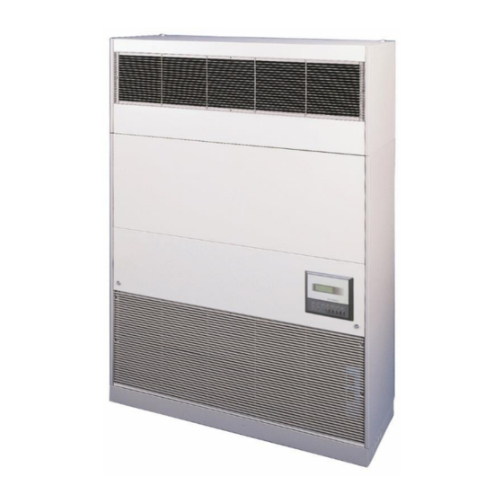
CD3 (929 SERIES) PACKAGED DX CLOSE CONTROL UNITS.
FOR USE IN SPLIT SYSTEMS
This manual details technical, installation and operating information for the CD3 range (929 series)
DX indoor units for use in conjunction with 550 series CKC condensing units or 542 series DCU
ducted condensing units. Remove the expansion device from the outdoor condensing unit if the
CD3 unit has capillaries or expansion valves fitted.
Advertisement
Table of Contents

Related Manuals for Marstair 929 Series


Summary of Contents for Marstair 929 Series
- Page 1 CD3 (929 SERIES) PACKAGED DX CLOSE CONTROL UNITS. FOR USE IN SPLIT SYSTEMS This manual details technical, installation and operating information for the CD3 range (929 series) DX indoor units for use in conjunction with 550 series CKC condensing units or 542 series DCU ducted condensing units.
-
Page 2: Table Of Contents
INDEX GENERAL General description and part numbers - DX upflow package units - DX configured units - Condensing units - DX configurable accessories Dimensions and weights SELECTION Unit combinations Performance data DX Airflows Sound levels - CD3 units, outdoor/ducted units INSTALLATION Airflow options Indoor unit... -
Page 3: Dx Upflow Package Units
GENERAL INTRODUCTION The CD3 range of direct expansion units is designed to provide the close control of temperature and humidity demanded by computer rooms, laboratories, banks, offices etc.. All units are fitted with programmable microprocessor controls. CD3 indoor units are available in upflow or downflow configurations, matching with the Marsatair range of CKC and DCU outdoor/ducted condensing units using R407C refrigerant. -
Page 4: Condensing Units
DX UPFLOW & DOWNFLOW CONFIGURED UNITS COOLING MODEL CD3 008 CD3 010 CD3 015 CD3 020 CIRCUITS 92918006 92918008 92918010 92918012 UPFLOW 92918007 92918009 92918011 92918013 92918014 92918016 92918018 92918020 DOWNFLOW 92918015 92918017 92918019 92918021 CONFIGURABLE UNIT FEATURES Electronically controlled fan speeds Microprocessor controls Class 'O' thermal and acoustic insulation Display giving access to set points and alarms... - Page 5 CD3 DX UNIT CONFIGURABLE ACCESSORIES (All options are factory fitted or supplied loose for site fitting during installation) Factory Factory Description Model Fitted Description Model Fitted Part No. Part No. 008/1 92900468 ALARMS 010/1 92900469 High water level 92919064 015/1 92900470 Water spillage indication (no pump) 92919067...
-
Page 6: Dimensions And Weights
DIMENSIONS AND WEIGHTS CD3 INDOOR UNITS UPFLOW UNITS (With plenum fitted) UNPACKED PACKED Model HEIGHT mm 1595 1595 1595 1595 1755 1755 1755 1755 WIDTH mm 1230 1380 1380 1580 1250 1400 1400 1600 DEPTH mm WEIGHT kg DOWNFLOW UNITS UNPACKED PACKED Model... - Page 7 SELECTION PRODUCT SELECTION Systems can be selected to provide either comfort cooling or cooling with higher sensible heat ratios CD3 COMBINATIONS AND DX PERFORMANCE DATA (nominal cooling capacities in kW) CD3 MODEL AIRFLOW (maximum) ³/s 0.78 1.04 1.23 1.51 HIGH SENSIBLE COOLING SYSTEMS CKC/DCU 1 x 80 2 x 30...
-
Page 8: Airflows
AIRFLOWS (m³/s) Model Fan speed Airflow 0.42 0.78 0.67 1.04 0.72 1.23 0.92 1.51 m³/s Note: Maximum external resistance at the maximum speed = 150Pa (Maximum fan speed) Model Airflow m³/s 0.81 0.78 0.78 0.78 1.14 1.14 1.74 1.74 1.74 1.74 Note: All CKC units are fitted with fan speed control that will allow the fan to stop during normal operation. -
Page 9: Airflow Options
INSTALLATION CD3 AIRFLOW OPTIONS 92908135-17... -
Page 10: Indoor Unit
CD3 SERIES CLOSE CONTROL UNIT INSTALLATION An envelope containing important user information is supplied with the indoor unit. Please pass to the end user. The Packaged units are supplied for Upflow operation with front return air and top discharge. Configured units are supplied for Upflow or Downflow operation. Standard upflow units are supplied with front return air and top discharge;... - Page 11 UPFLOW SERVICE AND FIXING HOLE CENTRES (excluding discharge plenum) COIL SECTION Note: Plenum (not shown) is 430mm high UNIT SIZE DIMENSION 'A' DIMENSION 'B' 1230 010 / 015 1380 1580 92908135-17...
- Page 12 DOWNFLOW SERVICE AND FIXING HOLE CENTRES UNIT DIMENSION 'A' DIMENSION 'B' 1230 010/015 1380 1580 92908135-17...
- Page 13 INSTALLATION of 550 Series CKC CONDENSING UNITS CKC units include fan speed control, high & low pressure switches with low ambient and compressor delay start timers. Note: It is easier to fit any kits prior to mounting the unit. The units are designed to stand on a flat surface. If they are to be wall mounted the following kits are available. (TEV Ltd cannot accept liability for installers own mounting arrangements).
- Page 14 INSTALLING 542 SERIES DUCTED CONDENSING UNITS MOUNTING Units are supplied with a polystyrene packing piece supporting the blower assembly, this MUST be removed prior to commissioning. Ducted Units are designed to be hung on a wall (kit available), suspended from a ceiling (installer supplied fittings), or to stand on a flat surface.
- Page 15 SUSPENSION MOUNTING The installer must supply 4 x M8 threaded rods with 16 nuts and washers to suit. IMPORTANT: The stabilizing brackets provided MUST be used when suspending a unit. Fit the stabilizing brackets to the top corners of the back panel and front face using the No. 10 screws provided, (2 per bracket).
- Page 16 APPLICATION APPLICATION To maximise performance, pipe runs should be kept as short as possible, avoiding sharp bends. Individual pipe runs to a maximum of 45m are allowed for air conditioners, providing pipe work is sized and installed correctly. Performance ratings are based on 6m pipe runs but there will be no significant loss of capacity on extended pipe runs for correctly sized pipes.
-
Page 17: Refrigeration Installation
REFRIGERATION INSTALLATION Units are supplied with the following pipe connections (in inches):- Model 008S 008T 010S 010T 015S 015T 020S 020T Liquid Suction S = Single Circuit T = Twin Circuit NOTE: On twin circuit units, the lower half of the coil is the first circuit. Using a tube cutter, remove sealed ends of suction and liquid pipes. -
Page 18: Electrical Data
Undercharged Unit - the top few tubes of the evaporator are dry and there are, (possibly), slight signs of frosting at the inlet to the evaporator coil. Overcharged Unit - the suction line 'sweats' all the way back to the compressor. ELECTRICAL CONNECTIONS The installation wiring should be carried out in accordance with I.E.E. -
Page 19: Fuses
Typical control panel and terminal layout RECOMMENDED FUSE SIZES The system and its supply/interconnecting wiring must be protected by fuses, preferably H.R.C. motor rated types to BS60269 or miniature circuit breakers to BS60898 or local codes having similar time lag characteristics that allow starting of the compressor yet still afford close over current protection under running conditions. -
Page 20: Condensate Drain
CONDENSATE DRAIN The condensate drain connection is at the left hand end of the condensate drain tray. A 15mm O.D. copper drain pipe is provided in the drain sump for connection with non-kink plastic tubing secured with a suitable clip. Should it be necessary for the drain pipe to go through the back or base of the unit, a knockout is provided in the back panel or base plate. - Page 21 WIRING DIAGRAMS POWER WIRING DIAGRAM – Sheet 1 92908135-17...
- Page 22 POWER WIRING DIAGRAM – Sheet 2 92908135-17...
- Page 23 CONTROL WIRING DIAGRAM For HUMIDIFIER wiring diagram see page 27. 92908135-17...
- Page 24 CKC WIRING DIAGRAMS indoor unit indoor unit 1 PHASE CKC 30 to 90 3 PHASE CKC 30 to100 indoor unit indoor unit 3 PHASE CKC 130 to 180 3 PHASE CKC 200 92908135-17...
- Page 25 DCU WIRING DIAGRAMS DCU 30 to 80 1 phase DCU 15 to 80 3 phase INTERCONNECTING WIRING DIAGRAMS 92908135-17...
- Page 26 1 phase units 3 phase units WAGO terminals Ø ( mm ) (mm²) 92908135-17...
-
Page 27: Condensate Pump
ACCESSORIES CONDENSATE PUMP (OPTIONAL) An optional condensate pump is available, providing a 5m lift where gravity drain is not an option. The full assembly comprises a condensate pump (suitable for hot and cold water removal), a control board, a float switch to activate the pump and a second float switch to provide a high water level alarm. - Page 28 Setting the capacity limitation “Sx%” Use the potentiometer “Sx%” to set the capacity limitation in % of the minimum capacity (setting range: 25…100%, factory setting: 100%). Setting the humidity setpoint value “%rH” Use the potentiometer “%rH” to set the humidity setpoint value for the internal controller in % relative humidity (setting range: 0…100%, factory setting: 100%).
-
Page 29: Pconet Parameters
Connect pCOnet via RS485 to a computer: during configuration, the CAREL RS485 converter (CVSTDMOR0) for USB ports can be used, Marstair part number 92919136. USB converters should not be used in the installation due to the large volume of data transmitted across a complex BACnet network. - Page 30 DATABASE OF THE SUPERVISOR The variables reported below will be transmitted between pCO and supervisor only if all the following conditions will be met: the serial card is inserted into the proper connector that is found on the interface the supervisory function is enabled in the M_MANUF_CONF1.window protected by manufacturer’s password the address of the unit is properly selected with reference to the supervisory network in the M_PARAM_USER12 window protected by user password.
- Page 31 Whole Variables Address Description Type Communication type Delay common alarm relay Whole Writing / Reading Cold 0/10V valve ramp start Whole Writing / Reading Cold 0/10V valve ramp end Whole Writing / Reading Warm 0/10V valve ramp start Whole Writing / Reading Warm 0/10V valve ramp end Whole Writing / Reading...
-
Page 32: Auto Change Over
4. Network: If communication is broken. Critical alarms are set in the Engineering Level mask (see operating Instructions page 5of 9) note that only AL01 and ALO2 are used with Marstair condensing units. AL03, AL04, AL32 and AL33 are not available. WIRING WARNING !! Units can start automatically, isolate both units before beginning work.. -
Page 33: Microprocessor Control
UNIT ASSIST In this mode the stand-by unit is enabled if the room temperature drifts out of limits, subject to a 3 Minute delay. This allows the run unit to control the temperature, and not respond to fast transients. Low temp alarm High temp alarm Unit Run unit... - Page 34 00:00 00/00/00 Unit 1 Temperature 00.0 °C Humidity 00.0% Unit On KEYPAD FUNCTIONS FUNCTION FUNCTION Displays measured Setting of operating values. parameters and safety Returns operator to the thresholds. main mask window. Displays the version of the Displays working hours and application programme loaded allows counter re-set.
- Page 35 OPERATING SEQUENCE When the unit is first powered up the display will show; SELF TEST - PLEASE WAIT. Once the self test has been completed the MAIN MASK will be displayed. This is the default screen. Current time Date Mask Number 00:00 00/00/00 M:01...
- Page 36 UNIT FAN SPEED HIGH AUTO RESTART AFTER BLACKOUT ENABLE REMOTE ON/OFF NEW USER PASSWORD 0000 ENGINEERING LEVEL ACCESS (Password required) PROGRAMME BUTTON MENU SERVICE PASSWORD Press 0000 LIMITS SET POINT TEMPERATURE: 15°C 30°C LIMITS SET POINT HUMIDITY TEMPERATURE COOL DIFFER. 1.0°C HEAT DIFFER.
- Page 37 TEMPERATURE ALARM LOW OFF SET 5.0°C HIGH OFF SET 5.0°C HUMIDITY ALARM LOW OFF SET HIGH OFF SET SEL. TYPE ALARM S = SERIOUS N = NOT SERIOUS AL01: NNNNS AL06: NNNS AL10: NSSSS AL15: NNNN SEL. TYPE ALARM S = SERIOUS N = NOT SERIOUS AL19: NSNNN AL24: SNNN...
- Page 38 Alarm E10 – Humidifier Low Current AL11 High Return Air temperature AL30 AL12 AL31 Clock alarm Low Return Air temperature AL13 AL32 High Pressure Circuit 1 High Return Air humidity AL14 Low Return Air humidity AL33 High Pressure Circuit 2 AL15 Not used AL34...
- Page 39 ENABLE AUTOMATIC HUMIDITY SET POINT VARIATION HUMIDITY TIME ZONE N.1 START HOUR 00:00 SET POINT 000.0% HUMIDITY TIME ZONE N.2 START HOUR 00:00 SET POINT 000.0% HUMIDITY TIME ZONE N.3 START HOUR 00:00 SET POINT 000.0% HUMIDITY TIME ZONE N.4 START HOUR 00:00 SET POINT...
- Page 40 Press to return to the MAIN MASK MAINTENANCE BUTTON MENU WORK HOURS Press 000000 COMPRESSOR 1 000000 COMPRESSOR 2 000000 HISTORY ALARM AL00 00:00 00/00/00 SET T: 00.0 T: 00.0 SET H : 000.0 H: 000.0 SERVICE PASSWORD 0000 H. THRESHOLD 100 x 1000 RESET No 000000...
- Page 41 The manual operating procedure may only be activated when the unit is in standby mode. In this mode the ON/OFF button is in OFF. MANUAL PROCEDURE MAIN FAN ENERGY SAVING MANUAL PROCEDURE DE-HUMIDIFIER HUMIDIFIER MANUAL PROCEDURE COMP 1 / CW OPEN COMP 2 / CW CLOSE MANUAL PROCEDURE HEAT 1 / LPHW OPEN...
- Page 42 COMPONENT IDENTIFICATION Note: The position of some of the controls shown in this diagram may vary from those in the unit delivered. Coil Filter Electrics access Drain tray Transformer Washable filter Access panel Discharge grille Return air grille Terminal Relay Humidity sensor Contactor Fan speed control...
- Page 43 COMPONENT IDENTIFICATION ITEM No. DESCRIPTION ITEM No. DESCRIPTION Electrics access panel Fan assembly Handle Right hand access panel Suction service valve Spire clip Isolator LP switch auto End clamp HP switch auto Terminal 4 way terminal Power board PCBA Fused terminal Overload (3 phase) Compressor Contactor...
- Page 44 CKC 30 – 100 ITEM No. DESCRIPTION ITEM No. DESCRIPTION ITEM No. DESCRIPTION Service valve Motor LP switch auto Service valve Contactor Valve panel Terminal end clamp Overload (3 phase) Base Terminal Heat exchanger Mounting foot Fuse Rear access panel Compressor Fuse terminal Mains terminal cover...
- Page 45 CKC 130 to 200 ITEM No. DESCRIPTION ITEM No. DESCRIPTION ITEM No. DESCRIPTION HP switch auto Handle Fuse terminal Switch bracket Front access panel Fuse LP switch auto Fan guard Terminal Switch bracket Fascia panel Terminal 4 way Bulkhead panel Support bracket Contactor Expansion assembly...