Table of Contents
Advertisement
Quick Links
`
WM:
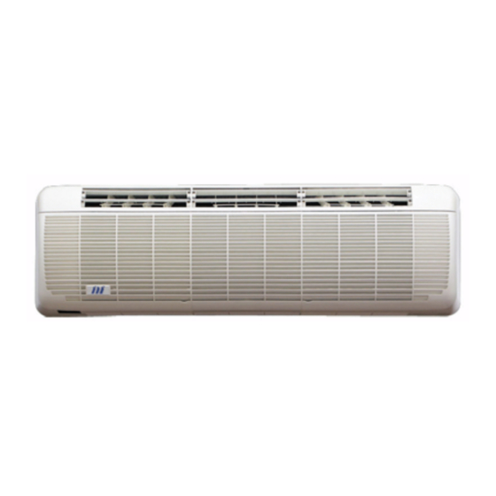
REMOTE WIRED HIGH WALL SPLIT SYSTEMS
WM L, WM E:
INFRARED HIGH WALL SPLIT SYSTEMS
INDOOR UNIT:
556 series WM, WM L, or WM E
MATCHED WITH:
550 series MCU or MCU+ condensing units (MCUP=MCU+ in Germany)
551 series MHPUE or MHPUL heat pump units
542 series DCUE ducted condensing units
543 series DHPUE ducted heat pump unit
GENERAL
PRODUCT
SELECTION
INSTALLATION
WIRING
DIAGRAMS
WM (L) (E) KITS
Remote return air sensor (for WM RCC30 controller)
Programmable timer (for WM)
Electric heaters
OPERATING
INSTRUCTIONS
COMPONENT
IDENTIFICATION
FAULT FINDING
Marstair Ltd,
Armytage Road, Brighouse,
West Yorkshire, HD6 1QF, UK.
Tel: +44 (0) 1484 405600
Fax: +44 (0) 1484 405620
Email: sales@marstair.com
TECHNICAL MANUAL
Part numbers
Dimensions and weights
Unit combinations, features/accessories
Essential Range systems
Optional electric heating
Airflows, air throws
Sound power and pressure levels
Performance data
Electrical data
Fuses
WM (L) (E) unpacking
Removing the case
Hanging the unit
Pipework and restrictors
Gravity drain; cable routing
Fitting the case
Fitting filters
MCU, MCU+, MHPUL, MHPUE installation
DCUE, DHPUE installation
Pipe sizing
Interconnecting wiring
WM L pcb jumper configuration
Remote controller WM (RCC 30: including operation)
WM L
WM E
Evacuating and charging
Adding refrigerant and oil
Check list: filter maintenance
WM, WM L, WM E
MCU, MCU+, MHPUL, MHPUE
DCUE, DHPUE
Interconnecting diagrams
5m high condensate pump
EMC termination kit
BMS alarm interface kit
Infrared WM L
Infrared WM E
Exploded view of chassis with component identification
Exploded view of case
Outdoor units
Ducted units
All models
-1-
2
3
4
4
5
5
6
7
8
9
14
14
15
16
17
17
18
19
20
22
23
24
25
25
26
27
28
29
32
35
38
41
41
42
44
46
47
48
50
54
55
56
57
58
55699105-03
Advertisement
Table of Contents

Related Manuals for Marstair WM


Summary of Contents for Marstair WM
- Page 1 REMOTE WIRED HIGH WALL SPLIT SYSTEMS WM L, WM E: INFRARED HIGH WALL SPLIT SYSTEMS INDOOR UNIT: 556 series WM, WM L, or WM E MATCHED WITH: 550 series MCU or MCU+ condensing units (MCUP=MCU+ in Germany) 551 series MHPUE or MHPUL heat pump units...
- Page 2 HIGH WALL SPLIT SYSTEMS The WM range of split systems consists of WM high wall units using remote wired controllers and WM L and WM E high wall units using infrared controllers matched with 550 series condensing units, 551 series heat pump outdoor units, 542 series electronic ducted condensing units or 543 series ducted heat pumps.
-
Page 3: Dimensions And Weights
UNPACKED DIMENSIONS AND WEIGHTS WM (L) (E) Model HEIGHT mm 1200 1500 1800 WIDTH mm DEPTH mm WEIGHT kg CONDENSING UNITS Model MCU(+)50 MCU (+) 60 MCU (+) 80 MCU (+) 90 MCU (+) 100 HEIGHT mm 1000 1000 1000... - Page 4 UNIT COMBINATIONS Combinations of indoor unit and (ducted) condensing/heat pump unit can be chosen to give either air conditioning or heat pump systems. Air Conditioners Heat Pumps MCU(+) DCUE WM L MHPUL WM E MHPUE DHPUE FEATURES/ACCESSORIES INDOOR UNITS WM L...
- Page 5 OPTIONAL ELECTRIC HEATING (kW) WM (L) (E) 230V 50Hz 240V 50Hz AIRFLOWS LOW SPEED MEDIUM SPEED HIGH SPEED WM (L) (E) 0.17 0.19 0.28 0.24 0.31 0.37 0.25 0.34 0.49 AIR THROWS o--o--O--O--O--o--o--...
- Page 6 SOUND POWER and SOUND PRESSURE LEVELS 556 SERIES WM (L) (E) SOUND POWER LEVELS Frequency Hz SOUND PRESSURE LEVELS MODEL SPEED 36.8 39.1 38.8 34.4 31.7 41.0 43.4 45.8 45.1 39.6 35.4 46.7 48.6 50.6 50.4 46.6 39.0 39.1 44.3 47.2...
-
Page 7: Performance Data
AIR CONDITIONER PERFORMANCE DATA (kW) UK Conditions: Room 21 / C / 15 / C Ambient 27 / C /19 / C Medium High MCU+ WM L SENS SENS SENS MCUP WM E DCUE 0.67 0.68 0.73 0.65 0.68 0.71 0.68... - Page 8 ELECTRICAL LOADS: Amps (230V 50Hz 1Ph) or A/Ph (400V 50Hz 3PhN) WM (L) (E) Fan Motor Electric heater MCU / MCU+ / MCUP MHPUL / MHPUE DCUE DHPUE Fan motor R407C 1Ph 10.2 10.9 15.0 10.9 15.0 10.5 11.8 14.8 10.5...
- Page 9 H = + Electric Heaters / + Batterie Electrique / Mit Elektroheizung H= 1.2 kW {WM 60 (L) (E)}, H = 1.7 kW {WM 80 (L) (E)}, H = 2.1 kW {WM100 (L) (E)}, @ 230V 3Ø - 400 V R407C / R22 FUSE RATING (A/Ø) / TAILLE DES DISJONCTEURS (A/Ph) / EMPFOHLENE SICHERUNG (A/Ph)
-
Page 10: Electrical Data
20 / C/12 / C, 7 / C/6 / C WM (L) (E) DCUE AMPS c) R407C: WM (L) (E) + MHPUL / MHPUE COOLING 1Ph 230V 50Hz 3Ph 400V 50Hz 27 / C/19 / C, 35 / /24 / C... - Page 11 R407C: WM (L) (E) + DHPUE COOLING 1Ph 230V 50Hz 3Ph 400V 50Hz 27 / C/19 / C, 35 / /24 / C SYSTEM SYSTEM MAX. FULL LOAD FULL LOAD MAX. INPUT STARTING INPUT CURRENT AMPS STARTING CURRENT CURRENT...
- Page 12 17.4 HEATING (230V 50Hz) 20 / C/12 / C, 7 / C/6 / C DCUE AMPS g) R22: WM (L) (E) + MHPUL / MHPUE COOLING 1Ph 230V 50Hz 3Ph 400V 50Hz SYSTEM SYSTEM 27 / C/19 / C, 35 / /24 / C FULL LOAD MAX.
- Page 13 R22: WM (L) (E) + DHPUE COOLING 1Ph 230V 50Hz 3Ph 400V 50Hz 27 / C/19 / C, 35 / /24 / C SYSTEM SYSTEM MAX. FULL LOAD FULL LOAD MAX. INPUT STARTING INPUT CURRENT AMPS STARTING CURRENT CURRENT...
- Page 14 -14-...
- Page 15 INSTALLATION HANGING RAIL FIXING THE HANGING RAIL HANGING THE CHASSIS -15-...
- Page 16 REFRIGERATION PIPEWORK / TUYAUTERIES / ROHRLEITUNGEN MAXIMUM EQUIVALENT PIPE LENGTHS (M) LONGUEURS EQUIVALENTES TUYAUTERIES MAXI (M) MAXIMAL ÄQUIVALENTE ROHRLEITUNGSLÄNGEN (M) RESTRICTOR ASSEMBLY / ASSEMBLAGE DE L’ACCURATEUR / DÜSENVORRICHTUNGEN RESTRICTOR SIZES / NUMÉRO DES BUSES DE DÉTENTE / DÜSENGRÖßE PIPEWORK CONNECTION / RACCORDEMENT DES TUYAUTERIES / ROHRLEITUNGEN -16-...
-
Page 17: Fitting The Case
GRAVITY DRAIN CABLE ROUTING FITTING THE CASE FITTING THE FILTERS -17-... - Page 18 Kits are more easily fitted prior to mounting the unit. Units are designed to stand on a flat surface. If the unit is to be wall mounted the following kits are available:- (Marstair Ltd cannot accept liability for installers own mounting arrangements). Model...
- Page 19 542 SERIES DUCTED CONDENSING UNITS These units have electronic fan speed control, start delay timer, HP and LP switches and a contactor fitted as standard; stabilizing brackets are supplied loose . It is generally preferable to fit the following kits (if applicable), prior to mounting the unit:- PTC kit (Positive Temperature Coefficient resistor) for use on 1Ph systems, particularly on long pipe runs.
-
Page 20: Pipe Sizing
SUSPENSION MOUNTING The installer must supply 4 x M8 threaded rods with 16 nuts and washers to suit. IMPORTANT: The stabilizing brackets provided MUST be used when suspending a unit. Fit the stabilizing brackets to the top corners of the backpanel and front face using the No. 10 screws provided, (2 per bracket). - Page 21 PIPE CONNECTIONS Pipework is terminated with flare nut connectors, adjacent to the access panel. Units are supplied with the following male flare connections (sizes in inches):- Model WM (L) (E) MCU / MCU+ / MCUP / DCUE MHPUL (E) Size...
-
Page 22: Interconnecting Wiring
Electromechanical models: In order to automatically switch off the fan in the event of a fire, fit an external switch (240V, 3A, closed to run, volt free contact) between terminal block terminal 2 and the Marstair remote control terminal L. - Page 23 -23-...
- Page 24 -24-...
- Page 25 Operating instructions are on page 16. WM E REMOTE CONTROLLER. WM E indoor units are supplied with a remote controller, wall mounting bracket, PP3 (9 volt) battery, screws and wall plugs. The controller operates either remotely by infrared signals, when the wall mounting bracket may be used to park the controller for convenience, or may be hard wired to the unit (via the wall mounting bracket) in applications where infrared is inappropriate, e.g., high lighting level, no direct line of sight etc..
- Page 26 -26-...
- Page 27 LENGTH OF EXPANSION LINE (m) / LONGUEUR DE LA LIGNE EXPANSION (m) / LÄNGE DER EXPANSIONSLEITUNG (m) MCU, MCU+ < = 8 WM (L) (E) R407C R407C R407C R407C R407C R407C R407C R407C R407C R407C R407C R407C R407C R407C R407C...
- Page 28 Failure to do so will cause a decline in unit performance and may result in malfunction We recommend that, in order to prolong the life and maintain performance of WM (L) (E) units, they are regularly serviced by an Marstair Ltd installer/dealer.
-
Page 29: Electric Heaters
WM WIRING DIAGRAM (see page 31 for accessories) BROWN MARRON BRAUN BLACK NOIR SCHWARZ BLUE BLEU BLAU GREEN VERT GRUN GREY GRIS GRAU ORANGE ORANGE ORANGE PINK ROSE ROSA ROUGE TURQUOISE TURQUOISE TUERKIS VIOLET VIOLET VIOLET WHITE BLANC WEIS YELLOW... - Page 30 WM L AIR CONDITIONER WIRING DIAGRAM WM L HEAT PUMP WIRING DIAGRAM -30-...
- Page 31 WM E WIRING DIAGRAM -31-...
- Page 32 MCU WIRING DIAGRAMS 1 Phase MCU 50-90 3 Phase MCU 50-100 MCU(+) WIRING DIAGRAMS 1 Phase MCU+ 50-90 3 Phase MCU+ 50-100 -32-...
- Page 33 MHPUL WIRING DIAGRAMS 1 Phase MHPUL 50 1 Phase MHPUL 80-90 -33-...
- Page 34 3 Phase MHPUL 50- 90 MHPUE WIRING DIAGRAMS 1 Phase MHPUE 50 -34-...
- Page 35 1 Phase MHPUE 80-90 3 Phase MHPUE 50-80 -35-...
- Page 36 ELECTRONIC DCUE WIRING DIAGRAMS 1 Phase DCUE 50 - 60 1 Phase DCUE 80 -36-...
- Page 37 3 Phase DCUE 50- 80 ELECTRONIC DHPUE WIRING DIAGRAMS 1 Phase DHPUE 50 -37-...
- Page 38 3 Phase DHPUE 50 INTERCONNECTING WIRING / INTERCONNEXIONS /VERBINDUNGSVERDRAHTUNG -38-...
- Page 39 INTERCONNECTING WIRING / INTERCONNEXIONS /VERBINDUNGSVERDRAHTUNG WM L -39-...
- Page 40 INTERCONNECTING WIRING / INTERCONNEXIONS /VERBINDUNGSVERDRAHTUNG WM E -40-...
- Page 41 --o--o--O--O--O--o--o-- PROGRAMMABLE TIMER KIT 52500151 This kit can be used to give ON/OFF switching of the mains voltage control circuits of WM units where the total current does not exceed 3 Amps. ELECTRIC HEATER CURRENTS CANNOT BE SWITCHED DIRECTLY.
- Page 42 55600401/402/403 Cable ties These kits are for use on WM (L) (E) wall mounted units. It is easier to fit the kit prior to installing the unit. ISOLATE THE SYSTEM PRIOR TO FITTING THE KIT IF THE UNIT HAS BEEN INSTALLED 1.
- Page 43 3. WIRING WM L, and WM E a) Route the harness from the fuse along the back panel using the cable clamps, ensuring the harness is above the cabinet fixing brackets b) Connect the black wire from the fuse assembly to the PCB relay: to ’HTR’...
- Page 44 DESCRIPTION Pump assembly This kit is for use on all versions of WM (L) (E) units and is for condensate removal where a lift of up to 5m is required. The pump runs on demand. A high level alarm will switch off the cooling signal until condensate has dropped below a pre-set level.
- Page 45 3. WIRING a) Locate the black, blue and red wires in the unit near the pump and remove the cover from the black and blue wires. b) Connect: (i) Black wire to terminal L on the pcb (ii) Blue wire to terminal N on the pcb The plastic cover over the pcb can be removed for convenience: retain the cable tie.
- Page 46 EMC TERMINATION KIT 55200301 This termination gland is required on all WM E units wherever low voltage signal cables are used (see table below), to maintain compliance with the EMC Directive. One termination gland can be used for up to 3 cables.
- Page 47 BMS alarm interface board Mounting foot (long: 4 for 600 E, 3 for *75E) Mounting foot (self adhesive for IMPACT-E) Orange wire Mounting foot (hook type for IMAGE-E, WM E) Yellow wire ISOLATE THE SYSTEM ELECTRICALLY BEFORE INSTALLING THIS KIT MOUNTING 1.
- Page 48 'L' INFRARED REMOTE CONTROL • The handset should be pointed towards the unit. • Two seconds after the last button press, the whole displayed programme is automatically transmitted. • The unit responds with 1 beep. The transmit symbol A flashes whilst transmission is taking place. •...
-
Page 49: Outdoor Units
7. Setting the ON Time Press the TIMER ON set ‘S’ button and step to the required ON time. Hold the button down for repeated stepping. Press the TIMER ON ‘C’ button to cancel the ON time. 8. Setting the OFF Time Press the TIMER OFF ‘S’... -
Page 50: Starting The Unit
INFRARED ‘E’ REMOTE CONTROLLER OPERATION Cool/Heat Modes (2.3): Fan Speeds (2.2): Cooling only Low fan speed Heating only High fan speed Auto cool/heat Boost fan speed Transmit Signal Fan only (2.1) Auto High Auto Boost Set Back Battery Indicator High temp set Low battery power (9) back (7.1) Low temp set... - Page 51 To change the fan speed: Illuminate the display (blue button). 2 3 4 Press (fan speed) button - the fan symbol will pulse. 2/3/4/23/2 4 Press the + or - ( • or – ) button to select the 5 fan speeds (see page 2), whilst pointing the handset towards the unit, (unless the handset is wire connected).
- Page 52 NOTES: l If an illogical selection is made (e.g. 'off' time earlier than 'on' time, or 'on' time with no 'off' time, or 'off' time with no 'on' E"" time), the programme will not move on to another day, or transmit, until the error is removed. will be displayed each time the DAY, or orange button is pressed, and the display will switch between 'on' and 'off' times until a logical time is...
- Page 53 Low battery power warning Low handset battery power is indicated by the battery symbol NOTES: When required, replace the battery with an equivalent alkaline type ensuring that the connector is firmly in position. Do NOT use a rechargeable battery. 9. LED Status and Alarm Indicators Electronic indoor units have coloured LED's and a sounder to indicate the following status and alarm functions.
- Page 54 EXPLODED VIEW OF WM (L) (E) with COMPONENT IDENTIFICATION 1 Back panel 16 Heater elements 31 Main PCB (WM L) 2 Condensate pump PCB 17 Heater coil retaining clip 32 Main PCB (WM E) 3 Condensate pump bracket 18 Heater cutout bracket...
- Page 55 9 Horizontal air deflector vane (lower) 2 Cover (centre) 6 Grille (R/H) 10 Horizontal air deflector vane (upper) 3 Cover (R/H) 7 Grille (centre) 11 Connecting rod 4 Filter 8 Grille (L/H) 12 Blank (WM): IR lens (WM L, WM E) -55-...
- Page 56 MCU(+) / MHPUL(E) COMPONENT IDENTIFICATION 13 Service valve (liquid) 25 Support bracket Contactor 14 Service valve (suction) 26 Fan / motor assy Overload 15 Valve panel 27 End clamp Heat exchanger Base 28 Terminal (screw - screw ) Rear access panel 17 Mounting foot 29 Fuse Mains terminal cover...
- Page 57 DCUE / DHPUE COMPONENT IDENTIFICATION Service valve Fan assembly Panel electrics access Panel right hand access Handle Accumulator Service valve Spire c lip Isolator Switch LP auto End clamp Switch HP auto Terminal Terminal 4 way Reversing valve (DHPUE) Terminal fused Solenoid Compressor Power board...
- Page 58 GENERAL FAULT FINDING (ALL SYSTEMS) CONDITION POSSIBLE CAUSE ACTION Check fuse rating and replace if necessary. Check for No electric supply at socket or switched fuse box Indoor fan motor will not run loose electrical connections Unit wiring fault Check wiring and connections Fan motor capacitor defective Replace if faulty Fan motor defective...
-
Page 59: Mhpul
SPECIFIC FAULT DIAGNOSIS FOR WM L UNITS CONDITION POSSIBLE CAUSE ACTION Check for alarms LEDs flashing - see table below If NO external connections are made to alarm terminal 5, the presence of an alarm condition can be tested for by checking for mains voltage at terminal 5;... - Page 60 SPECIFIC FAULT DIAGNOSIS FOR WM E UNITS A fully electronic system comprising WM E with MHPUE or DCUE communicates between the units by digital codes. Signals are transmitted every 10 seconds, therefore a delay of up to 10 seconds could occur before the system responds to a command. Similarly if the communication link is broken, the outdoor unit will shut down within 15 seconds.
Need help?
Do you have a question about the WM and is the answer not in the manual?
Questions and answers