Autonics LP-A Series User Manual
Logic panel
Hide thumbs
Also See for LP-A Series:
- User manual (138 pages) ,
- Quick start manual (3 pages) ,
- Product manual (3 pages)
Table of Contents

Related Manuals for Autonics LP-A Series


Summary of Contents for Autonics LP-A Series
- Page 1 User Manual Logic Panel LP-A Series Thank you for purchasing an Autonics product. This user manual contains information about the product and its proper use, and should be kept in a place where it will be easy to access. www.autonics.com...
- Page 2 © Copyright Reserved Autonics Co., Ltd.
-
Page 3: Preface
Preface Preface Thank you for purchasing Autonics product. Please familiarize yourself with the information contained in the Safety Considerations section before using this product. This user manual contains information about the porduct and its proper use, and should be kept in a place where it will be easy to access. -
Page 4: User Manual Guide
Visit our web site (www.autonics.com) to download a copy. The manual's content may vary depending on changes to the product's software and other unforeseen developments within Autonics, and is subject to change without prior notice. Upgrade notice is provided through out homepage. ... -
Page 5: User Manual Symbols
Failure to follow instructions can result in serious injury or death. Failure to follow instructions can lead to a minor injury or product damage. An example of the concerned feature's use. Annotation mark. ※1 © Copyright Reserved Autonics Co., Ltd. -
Page 6: Reference Manual For Each Configuration
Connected device setting, communication setting Drawing atDesigner User Manual Software Manual Programming atLogic User Manual, atLogic Programming Manual Hardware Manual LP-A Series User Manual Check connectable device, connection cable model name and protocol Communication Manual GP/LP Communication Manual © Copyright Reserved Autonics Co., Ltd. -
Page 7: Safety Considerations
Failure to follow this instruction may result in fire. Since Lithium battery is embedded in the product, do not disassemble or burn the unit. Failure to follow this instruction may result in fire. Please contact us for battery replacement. © Copyright Reserved Autonics Co., Ltd. - Page 8 The specifications are subject to change and some models may be discontinued without notice. Be sure to follow cautions written in the instruction manual, user manual and the technical descriptions (catalog, website). viii © Copyright Reserved Autonics Co., Ltd.
-
Page 9: Cautions During Use
If it gets into the eyes, rinse eyes with running water for over 15 minutes and contact a doctor. This unit may be used in the following environments. ①Indoors (in the environment condition rated in 'Specifications') ②Altitude max. 2,000m ③Pollution degree 2 ④Installation category II © Copyright Reserved Autonics Co., Ltd. -
Page 10: Table Of Contents
LP-A104...................... 28 1.8.3 Common ..................... 29 Installation ....................31 Device Installation ....................31 Power Wiring ..................... 32 Ground Wiring ....................33 Input Wiring ......................34 2.4.1 LP-A070...................... 34 2.4.2 LP-A104...................... 35 Output Wiring ..................... 36 © Copyright Reserved Autonics Co., Ltd. -
Page 11: Table Of Contents
......................71 8.1.1 atDesigner Overview .................. 71 8.1.2 atDesigner Feature ..................71 8.1.3 Connecting atDesigner and GP Device ............. 72 atLogic(Formerly, SmartStudio) ................. 73 8.2.1 atLogic Overview ..................73 8.2.2 atLogic Feature ..................73 © Copyright Reserved Autonics Co., Ltd. - Page 12 9.1.5 List of Word Special Device................ 91 9.1.6 UW Correspondence Table ................ 96 CAN Memory Mapping ..................97 9.2.1 Overview..................... 97 9.2.2 Memory Mapping Table ................98 Motion Control I/O Signal allocation ..............104 © Copyright Reserved Autonics Co., Ltd.
-
Page 13: Overview
Download the created data to LP, after editing data such as shape, layout, and attributes of various objects with atDesigner, and programming the PLC logic with atLogic, LP monitors or controls the control device according to the screen data. © Copyright Reserved Autonics Co., Ltd. -
Page 14: Features
Various objects can be used to display data in different ways depending on the purpose. The intuitive UI makes it easier to use the program. Supporting various fonts Supporting various bitmap fonts and vector fonts. Users are allowed to select the fonts. © Copyright Reserved Autonics Co., Ltd. -
Page 15: Ordering Information
RS232C, RS422, USB Device, USB Host, Ethernet, CAN, Micro SD ⑦Interface RS232C: 2, USB Device, USB Host, Ethernet, CAN, Micro SD ⑧Module type Integrated type IN: 32-point, OUT: 32-point ⑨Number of I/O Ribbon cable connector ⑩I/O connector Terminal block connector type © Copyright Reserved Autonics Co., Ltd. -
Page 16: Specifications
Fixing bracket: 4, battery (included) Approval ᜢ ᜣ Weight Approx. 742g (approx. 540g) ※1 ※1: The weight includes packaging. The weight in parenthesis is for unit only. ※Environment resistance is rated at no freezing or condensation. © Copyright Reserved Autonics Co., Ltd. - Page 17 Average: approx. 1 ㎲/basic command, application command I/O control type Batch processing Computer control mode Repeated-doubling method, interrupt processing Device range Refer to ‘9.1 Device’. Embedded special Positioning function, High speed counter function ※1: Supported language can be added. © Copyright Reserved Autonics Co., Ltd.
-
Page 18: Lp-A104 Series
Fixing bracket: 6, battery (included) Approval ᜢ ᜣ Approx. 1.66kg(approx. 1.10kg) Weight ※1 ※1: The weight includes packaging. The weight in parenthesis is for unit only. ※Environment resistance is rated at no freezing or condensation. © Copyright Reserved Autonics Co., Ltd. - Page 19 Average: approx. 1 ㎲/basic command, application command I/O control type Batch processing Computer control mode Repeated-doubling method, interrupt processing Device range Refer to ‘9.1 Device’. Embedded special Positioning function, High speed counter function ※1: Supported language can be added. © Copyright Reserved Autonics Co., Ltd.
-
Page 20: Functions
Saving the value of the designated device, when meeting the Logging condition (device/cycle) System logging Saving system operation information of GP in a log file Script Writing Lua script by user © Copyright Reserved Autonics Co., Ltd. -
Page 21: Logic Functions
Extension: input filter, external interrupt Parameter Workspace Motion: common setting, operation setting, pattern setting High speed counter Variable/ Comment Manage and set Variable/Comment by bit/word device Monitoring Monitor and register monitoring device by bit/word device © Copyright Reserved Autonics Co., Ltd. -
Page 22: Unit Description
1 Overview Unit Description 1.6.1 LP-A070 Program status LED LED Color LED Status Program Status Green Green Flashing Pause Flashing Error Orange atLogic debugging © Copyright Reserved Autonics Co., Ltd. -
Page 23: Lp-A104
1 Overview 1.6.2 LP-A104 Program status LED LED Color LED Status Program Status Green Green Flashing Pause Flashing Error atLogic debugging © Copyright Reserved Autonics Co., Ltd. -
Page 24: Communication Interface
Firmware upgrade Used as external storage by connecting Barcode reader to PC Printer USB HOST can cover up to 32GB of external storage. It supports only external storage of FAT16 and FAT32 file system © Copyright Reserved Autonics Co., Ltd. -
Page 25: Ethernet Interface
Tx: Transmit Data Rx: Receive Data (2) Cross cable Cable color Signal Pin no. Pin no. Signal White Orange Orange White Green Blue White Blue Green White Brown Brown Tx: Transmit Data Rx: Receive Data © Copyright Reserved Autonics Co., Ltd. -
Page 26: Can Interface
1 Overview 1.7.4 CAN Interface It is allowed to connect with ARD Series, Autonics’ Field network devices,using CAN communication. Arrangement Color Black 24VDC(-) Blue CAN_L None SHIELD White CAN_H 24VDC(+) Max. memory size per slave is 8byte. Digital module (ARM-D): 64 point ... -
Page 27: Dimension
1 Overview Dimension 1.8.1 LP-A070 (unit: mm) © Copyright Reserved Autonics Co., Ltd. -
Page 28: Lp-A104
1 Overview 1.8.2 LP-A104 (unit: mm) © Copyright Reserved Autonics Co., Ltd. -
Page 29: Common
1 Overview 1.8.3 Common © Copyright Reserved Autonics Co., Ltd. - Page 30 1 Overview © Copyright Reserved Autonics Co., Ltd.
-
Page 31: Installation
When installing LP product on panel, make 100mm of space from upper, lower, right, left side of the product on the panel and back side of panel. It is for preventing effect of electromagnetic waves and heat from other controllers. © Copyright Reserved Autonics Co., Ltd. -
Page 32: Power Wiring
When connecting power, supply power with the power supply which has inner protection circuit. If the power supply which does not have inner protection circuit is used, protection circuits such as fuse must be installed before using this. © Copyright Reserved Autonics Co., Ltd. -
Page 33: Ground Wiring
Caution for ground wiring Connect max. 100Ω of ground resistance. Diameter of cable for ground wiring connection should be over than 2 ㎟. As above figure, separate from other device’s ground wire. © Copyright Reserved Autonics Co., Ltd. -
Page 34: Input Wiring
The internal input module of LP-A070 series is NPN open collector (source type). LP-A070-T9D6(7)-C5R input wiring LP-A070-T9D6(7)-C5T input wiring (2) Wiring according to the input device type Connection with NPN open collector Connection with relay output type output type © Copyright Reserved Autonics Co., Ltd. -
Page 35: Lp-A104
The internal input module of LP-A104 series is NPN open collector (source type). LP-A104-T9D8(9)-C6R input wiring LP-A104-T9D8(9)-C6T input wiring (2) Wiring according to the input device type Connection with NPN open collector Connection with relay output type output type © Copyright Reserved Autonics Co., Ltd. -
Page 36: Output Wiring
LP-A070-T9D6(7)-C5T output wiring Separate the colors of the input/output wiring and do not wire to the same duct. Wire at least 100 mm away from power lines and other high voltage lines. © Copyright Reserved Autonics Co., Ltd. -
Page 37: Lp-A104
LP-A104-T9D8(9)-C6T output wiring Separate the colors of the input/output wiring and do not wire to the same duct. Wire at least 100 mm away from power lines and other high voltage lines. © Copyright Reserved Autonics Co., Ltd. - Page 38 2 Installation © Copyright Reserved Autonics Co., Ltd.
-
Page 39: System Organization
Link device communication available Ethernet port RS422 or RS232C-A port, Direct communication available RS232C or RS232C-B port, LP-A104 Link device communication available Ethernet port, CAN port ※ ※Only Autonics’ ARD Series can be connected to CAN port. © Copyright Reserved Autonics Co., Ltd. -
Page 40: 1:N Communication Of Same Controllers
Link device communication available Ethernet port RS422 or RS232C-A port, Direct communication available RS232C or RS232C-B port, LP-A104 Link device communication available Ethernet port, CAN port ※ ※Only Autonics’ ARD Series can be connected to CAN port. © Copyright Reserved Autonics Co., Ltd. -
Page 41: 1:N Communication Of Different Controllers
Link device communication available Ethernet port RS422 or RS232C-A port, Direct communication available RS232C or RS232C-B port, LP-A104 Link device communication available Ethernet port, CAN port ※ ※Only Autonics’ ARD Series can be connected to CAN port. © Copyright Reserved Autonics Co., Ltd. -
Page 42: 1:1:N Communication
Link device communication available Ethernet port RS422 or RS232C-A port, Direct communication available RS232C or RS232C-B port, LP-A104 Link device communication available Ethernet port, CAN port ※ ※Only Autonics’ ARD Series can be connected to CAN port. © Copyright Reserved Autonics Co., Ltd. -
Page 43: N:1:N Communication
Link device communication available Ethernet port RS422 or RS232C-A port, Direct communication available RS232C or RS232C-B port, LP-A104 Link device communication available Ethernet port, CAN port ※ ※Only Autonics’ ARD Series can be connected to CAN port. © Copyright Reserved Autonics Co., Ltd. -
Page 44: Barcode Reader, Printer Communication
(2) Communication specification Item Specification Baud rate 300, 600, 1200, 3200, 4800, 9600, 19200, 38400, 57600, 115200bps Data length 7, 8 bit Parity None, Odd, Even Stop bit 1, 2 bit Flow control DSR/DTR, XON/XOFF © Copyright Reserved Autonics Co., Ltd. -
Page 45: Printer
(2) Communication specification Item Specification Baud rate 300, 600, 1200, 3200, 4800, 9600, 19200, 38400, 57600 bps Data length 7, 8 bit Parity None, Odd, Even Stop bit 1, 2 bit Flow control DSR/DTR, XON/XOFF © Copyright Reserved Autonics Co., Ltd. - Page 46 3 System Organization © Copyright Reserved Autonics Co., Ltd.
-
Page 47: Operating Lp
Check the 3rd grounding. Check the wiring connections for polarity. Power cable Check the terminal screw tightness. Check the power supply voltage within rated range. Power Check the power is installed separately from other devices. © Copyright Reserved Autonics Co., Ltd. -
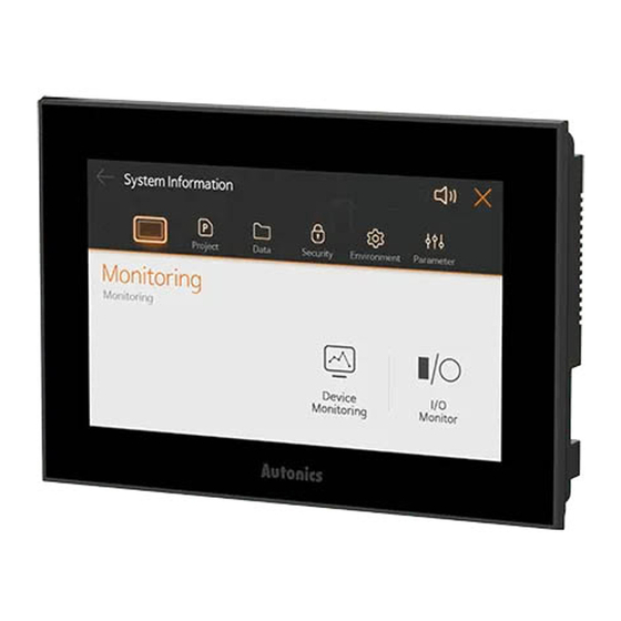
Page 48: Operation Procedure
Touch top-left Enter system information menu for system setting. Touch ‘X’ on top-right Quit system information menu and return to user screen. © Copyright Reserved Autonics Co., Ltd. -
Page 49: System Setting Menu
Print the alarm log to connected printer. Manage USB memory data connected to GP internal Data Management memory. Firmware Upgrade Upgrade the firmware Data Check the screen in use in a project downloaded in Security User Screen current GP. © Copyright Reserved Autonics Co., Ltd. - Page 50 Check the details in ‘Parameter’-‘Motion setting’- Action List ‘Operation List’ in atLogic. Parameter Check the details in ‘Parameter’-‘Motion setting’-‘Pattern Pattern List List’ in atLogic. Check the details in ‘Parameter’-‘High Speed Counter’ in HI Count atLogic. © Copyright Reserved Autonics Co., Ltd.
-
Page 51: Operating System Setting Menu
For LP-A070 Series, this button is enabled and the submenu is divided in to several ⑥ pages. For LP-A104 Series, all submenus can be checked on one page. Submenu of the currently opened system setting menu. ⑦ © Copyright Reserved Autonics Co., Ltd. -
Page 52: System Setting Menu Detailed Settings
(2) Device value setting When the device to be monitored is selected, the selected device and device value are displayed on the device monitoring screen. Device value can be set by touching device value. © Copyright Reserved Autonics Co., Ltd. -
Page 53: Project
Set the delay time of the boot screen. Delay The unit is seconds. Set whether to use the GP screen saver. Screen Saver Screen Saver When checked, the sub item is activated. © Copyright Reserved Autonics Co., Ltd. - Page 54 Set the key window to be used for the screen input device. It can be set individually for each input data type. It can be changed by touching the right button of the kepad type. © Copyright Reserved Autonics Co., Ltd.
- Page 55 If the screen capture image storage is full, Delete Oldest File for Full Area the oldest data file will be deleted in order. ※ Screen capture is a special device and operates when bit switch with device addres UB830is ‘ON’. © Copyright Reserved Autonics Co., Ltd.
- Page 56 Logging is a function to save the device value when the set conditions are met. Use to monitor the device. For detailed information about using and setting logging, please refer to ‘atDesigner user manual’. © Copyright Reserved Autonics Co., Ltd.
- Page 57 Print the alarm log to connected printer. Touch “Print” at the bottom center of the screen to print the alarm history to the connected printer. If there is no connected printer, there will be no action. © Copyright Reserved Autonics Co., Ltd.
-
Page 58: Data
Display basic screen (base screen), window screen, keypad screen, screen list of overlap screen. 5.3.3.4 Multilingual Table Check the details of the multilingual table of the project. Displays a list of saved contents for each language. © Copyright Reserved Autonics Co., Ltd. -
Page 59: Security
Set LP communication password and whether to use. If the password has been set in the device, it is possible to set to enter the password in project upload / download, firmware upgrade, exiting screen saver. © Copyright Reserved Autonics Co., Ltd. -
Page 60: Environment
EDITOR Sets the port to be connected to atDesigner (PC). Interface setting range: RS-232C, Ethernet, USB, Not used Set CAN communication port. DEVICE-NET It can be connected with Autonics ARD Series. Interface setting range: CAN, Not used Inner (Internal channel) The serial barcode setting for atDesigner is downloaded. - Page 61 Setting range: 1, 2 bit Ethernet Set the same value of communication specifications between controller and LP. Item Specification Port Setting range: 0~65535 Fixed ‘Communication mode: HID interface’. DEVICE-NET(CAN) Fixed ‘Communication mode: 500kbps’. © Copyright Reserved Autonics Co., Ltd.
- Page 62 Touch the 'start screen diagnosis' button at the center of the screen to display the screen in the order shown below, and touch any part of the screen to move on to the next screen. The diagnosis screen allows to check the color, pixel and font display for any abnormalities. © Copyright Reserved Autonics Co., Ltd.
- Page 63 Touching the Factory reset menu will show a screen asking whether the system is initialized. Touching 'Confirm' will lead to initialization, and it will be rebooted after completion. Do not turn off power while the system is initialized. © Copyright Reserved Autonics Co., Ltd.
-
Page 64: Parameter
'High Speed Counter' is an item to set the default action for using the high speed counter function. For detailed information about high speed counter’s function, please refer to ‘atLogic user manual, atLogic programming manual’. © Copyright Reserved Autonics Co., Ltd. -
Page 65: Troubleshooting
※ Use the cable (sold separately) sold by us to connect the LP to the external device and PC. For detailed information about the communication cable for each device, please refer to ‘GP/LP Communication manual’. © Copyright Reserved Autonics Co., Ltd. - Page 66 6 Troubleshooting © Copyright Reserved Autonics Co., Ltd.
-
Page 67: Repair / Maintenance / Inspection
Check the bracket Attached without shaking Tighten the screw status screw loosening Comm. Cable Check the cable Cable connection must be Tighten the screw connection connecting screw securely tightened Use genuine cable status loosening © Copyright Reserved Autonics Co., Ltd. -
Page 68: Regular Maintenance
Make sure to use a standard measuring devices, when inspecting the power supply voltage. When replacing the product, make sure to turn the power off. When removing dust or dirt, use a dry cloth that does not contain water or detergent. © Copyright Reserved Autonics Co., Ltd. -
Page 69: Firmware Upgrade
The upper left corner of the screen is the factory default for the system setting menu call button position. 5th Touch the ‘Firmware Upgrade’ menu in the [Data] menu. Do not turn OFF the LP’s power or remove USB memoriy during the firmware upgrade. © Copyright Reserved Autonics Co., Ltd. - Page 70 7 Repair / Maintenance / Inspection © Copyright Reserved Autonics Co., Ltd.
-
Page 71: Software
8.1.1 atDesigner Overview atDesigner is dedicated software for GP/LP-A Series that can edits all data for user screens and projects. It is allowed to edit data such as shapes, layouts and properites of various objects and figures on the screen, and set the project user account, security level, language, script, etc. and download to GP/LP. -
Page 72: Connecting Atdesigner And Gp Device
11th When the detailed setup is completed, click "OK" to connect atDesigner and GP. 12th Click "Download" under [Communications] to download the project from atDesigner to GP, or click "Upload" to upload it from GP to atDesigner. © Copyright Reserved Autonics Co., Ltd. -
Page 73: Atlogic(Formerly, Smartstudio)
Supports various message window for edit or check program easily. Real time switching ladder and mnemonic program Switching ladder or mnemonic program in real time and it is available to write or edit at two editors simultaneously. © Copyright Reserved Autonics Co., Ltd. -
Page 74: Connecting Atlogic And Lp Device
8 Software 8.2.3 Connecting atLogic and LP Device Connect atLogic and LP-A Series to download/upload projects and upgrade firmware. The communication between PC and LP-A series uses serial interface (RS-232C), Ethernet, USB interface. the method for connecting atLogic and LP deive is as follow below. -
Page 75: Appendix
304bit AREA USER UB0001000~UB128999F UB0001000~UB128999F 2,062,400bit AREA 9.1.2.2 Word Device Range notation Name Range UB corresponding address Size READ UW000000~UW000080 UW000000~UW000080 0008 Word AREA WRITE UW0000081~UW0000099 UW0000081~UW0000099 00019Word AREA USER UW0000100~UW0128999 UW0000100~UW0128999 128,900Word AREA © Copyright Reserved Autonics Co., Ltd. -
Page 76: List Of System Device
System Read Only signal 6 Turns ON in case of no mobile disk to Bit 2 store the system logging data Turns ON in case of no mobile disk to Bit 3 store the recipe data © Copyright Reserved Autonics Co., Ltd. - Page 77 System Read Only signal 29 (0~65535) Counter value at 5 seconds interval UW43 System Read Only signal 30 (0~65535) Counter value at 10 seconds interval UW44 System Read Only signal 31 (0~65535) UW45~80 Read Only area reserve © Copyright Reserved Autonics Co., Ltd.
- Page 78 When turns ON, all alarm history and Bit 1 occurrence count are deleted Bit 2 When turns ON, print the history alarm 9.1.3.3 User Area UW area Read area Write area UW100 User area User area … UW128999 © Copyright Reserved Autonics Co., Ltd.
-
Page 79: List Of Bit Special Device
Turns ON after the 2nd scan when PLC is run mode Scan Reverse every scan when PLC is run UB744014 F00014 pulse mode Time sync Synchronized pulse in RTC time UB744015 F00015 pulse © Copyright Reserved Autonics Co., Ltd. - Page 80 Time setting UB744036 F00036 error Turns OFF when time is written normally by RTC Turns ON when communication error occurs Communication UB744038 F00038 error Turns OFF when communication is made normally © Copyright Reserved Autonics Co., Ltd.
- Page 81 Turns OFF when SLOT7 parameter device does not use internal device Turns ON when SLOT8 parameter Use SLOT 8 UB74404 uses more than one internal device internal F00048 device Turns OFF when SLOT8 parameter © Copyright Reserved Autonics Co., Ltd.
- Page 82 Turns ON when SLOT15 parameter uses more than one internal device Use SLOT 15 UB74404 internal F0004F Turns OFF when SLOT15 device parameter does not use internal device © Copyright Reserved Autonics Co., Ltd.
- Page 83 Turns OFF when there is no F00068 (current) calculation error after completing one scan Turns OFF when program download or power reset Calculation Keep ON when calculation error UB74406 error flag F00069 occurs during scanning (maintain) © Copyright Reserved Autonics Co., Ltd.
- Page 84 When it is SET, operate filters on all Default undefined modules in parameters as filter default values UB744079 F00079 setting When it is RESET, operate without flag filters on all undefined modules © Copyright Reserved Autonics Co., Ltd.
- Page 85 UB74409B F0009B enable written to module register Set SLOT12 module When bit is ON, the function internal device internal device value is UB74409C F0009C enable written to module register © Copyright Reserved Autonics Co., Ltd.
- Page 86 UB74409E F0009E enable written to module register Set SLOT15 module When bit is ON, the function internal device internal device value is UB74409F F0009F enable written to module register © Copyright Reserved Autonics Co., Ltd.
- Page 87 1: enable operation list MTSRS operation specification flag UB744400 F00400 0: disable operation list (operation list end) MTSRS operation 1: enable group end UB744401 F00401 specification flag 0: disable group end (group end) © Copyright Reserved Autonics Co., Ltd.
- Page 88 1: enable operation list MTSRS operation UB744402 F00402 specification flag 0: disable operation list (operation list end) MTSRS operation 1: enable group end UB744403 F00403 specification flag 0: disable group end (group end) © Copyright Reserved Autonics Co., Ltd.
- Page 89 F00502 operation OFF fall: Jog deceleration and stop in ON rise: Jog acceleration in CCW, constant speed start CH2 Jog CCW UB744504 F00503 operation OFF fall: Jog deceleration and stop in © Copyright Reserved Autonics Co., Ltd.
- Page 90 High speed counter 1: match CH2 match value 2 UB744314 F00314 0: not match match status High speed counter 1: overflow CH2 current value UB744318 F00318 0: not overflow overflow status © Copyright Reserved Autonics Co., Ltd.
-
Page 91: List Of Word Special Device
Function device device Error step Currently stopped step due to error UW74530 F130 Braked step during the debug mode operation Brake step UW74531 F131 Reset when program is changed or PLC mode is changed © Copyright Reserved Autonics Co., Ltd. - Page 92 Save the day of the week setting value as BCD data Time setting (day 0: Sunday, 1: Monday, 2: Tuesday, UW74556 F156 of the week) 3: Wednesday, 4: Thursday, 5: Friday, 6: Saturday © Copyright Reserved Autonics Co., Ltd.
- Page 93 Periodic interrupt cycle setting 6 Periodic interrupt cycle setting 6 UW74576 F176 Periodic interrupt cycle setting 7 Periodic interrupt cycle setting 7 UW74577 F177 Periodic interrupt cycle setting 8 Periodic interrupt cycle setting 8 UW74578 F178 © Copyright Reserved Autonics Co., Ltd.
- Page 94 Current operation number of CH2 UW74474 number Pattern Current pattern number of CH2 UW74475 number Origin Current origin position of CH2 UW74476 position Setting Setting speed of CH2 UW74478 speed Check error Check error code of CH2 UW74421 © Copyright Reserved Autonics Co., Ltd.
- Page 95 High speed counter CH2 match value 2 F208 UW74608 Total pulse input number after counting CH2 total starts (64 bit) counting Current total counter number = Total F228 UW74628 number counting number + Current HNCNT counting number © Copyright Reserved Autonics Co., Ltd.
-
Page 96: Uw Correspondence Table
UB74999F UW74999 UB744000~ UW74400~ F0~F299F F0~F299 Special device UB74699F UW74699 UB741000~ UW74100~ V0~V299F V0~V299 Virtual device UB74399F UW74399 UB990000~ UW99000~ Link device L0~L9999F L0~L9999 UB99999F UW99999 UB020000~ UW02000~ File device R0~R3999F R0~R3999 UB05999F UW05999 © Copyright Reserved Autonics Co., Ltd. -
Page 97: Can Memory Mapping
Area assigned to read the current value of the module for the output of Slave connected to DeviceNet Size: 512byte=(max. number of connectable Slaves (63)+1)×Memory size per Slave (8byte) Address: UW66048 ~ UW66303 © Copyright Reserved Autonics Co., Ltd. -
Page 98: Memory Mapping Table
65612 65615 65616 65619 65620 65623 65624 65627 65628 65631 65632 65635 65636 65639 65640 65643 65644 65647 65648 65651 65652 65655 65656 65659 65660 65663 65664 65667 65668 65671 65672 65675 65676 65679 © Copyright Reserved Autonics Co., Ltd. - Page 99 65771 65772 65775 65776 65779 65780 65783 65784 65787 65788 65791 ※Module address 0 is not used. ※Maximum number of connectable slaves is 64, but connect only up to 8 units for system stabilization. © Copyright Reserved Autonics Co., Ltd.
- Page 100 65895 OUT(command) 65896 65899 OUT(command) 65900 65903 OUT(command) 65904 65907 OUT(command) 65908 65911 OUT(command) 65912 65915 OUT(command) 65916 65919 OUT(command) 65920 65923 OUT(command) 65924 65927 OUT(command) 65928 65931 OUT(command) 65932 65935 OUT(command) 65936 65939 © Copyright Reserved Autonics Co., Ltd.
- Page 101 66032 66035 OUT(command) 66036 66039 OUT(command) 66040 66043 OUT(command) 66044 66047 ※Module address 0 is not used. ※Maximum number of connectable slaves is 64, but connect only up to 8 units for system stabilization. © Copyright Reserved Autonics Co., Ltd.
- Page 102 66160 66163 OUT(current value) 66164 66167 OUT(current value) 66168 66171 OUT(current value) 66172 66175 OUT(current value) 66176 66179 OUT(current value) 66180 66183 OUT(current value) 66184 66187 OUT(current value) 66188 66191 OUT(current value) 66192 66195 © Copyright Reserved Autonics Co., Ltd.
- Page 103 OUT(current value) 66292 66295 OUT(current value) 66296 66299 OUT(current value) 66300 66303 ※Module address 0 is not used. ※Maximum number of connectable slaves is 64, but connect only up to 8 units for system stabilization © Copyright Reserved Autonics Co., Ltd.
-
Page 104: Motion Control I/O Signal Allocation
When the motion controller function and the high speed counter function are used at the same time, X0 to X5 are occupied by the motion controller and cannot be used as the input port of the high-speed counter. © Copyright Reserved Autonics Co., Ltd. - Page 105 9 Appendix © Copyright Reserved Autonics Co., Ltd.
- Page 106 * Dimensions or specifications on this manual are subject to change and some models may be discontinued without notice. MTL-LPAU1-V1.4-1909US...
Need help?
Do you have a question about the LP-A Series and is the answer not in the manual?
Questions and answers