
Related Manuals for Extraflame DEBBY


Summary of Contents for Extraflame DEBBY
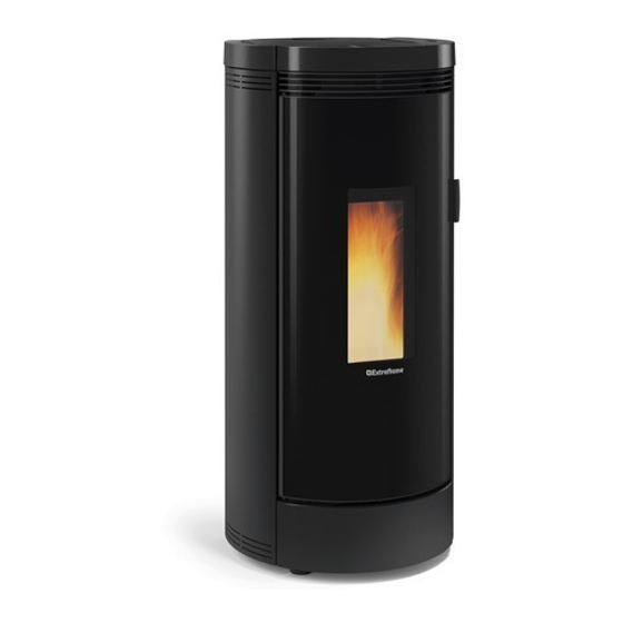
- Page 1 UsER MANUAl DEBBY MADE ITALY design & production 004280031 - Rev.001...
-
Page 3: Table Of Contents
HErMEtIcaLLy SEaLEd INStaLLatIoN ............................10 COMbUSTION AIR ............................................10 FUMES EXHAUST SYSTEM ........................................10 uppEr fuMES outLEt aSSEMbLy ..............................11 rEar fuMES outLEt aSSEMbLy ..............................12 dEtaILS dEbby ....................................13 StovE poSItIoNING ..................................14 NotE for corrEct fuNctIoNING ............................... 14 FUSE ................................................14 REARMING ..............................................14 pELLEtS aNd LoadING .................................. - Page 4 it - AttENZiONE tASSAtiVO EN - WArNiNg PrimA di mOVimENtArE lA StufA BEfOrE hANdliNg thE StOVE, thE tOgliErE il riVEStimENtO iNdicAtO cOVEriNg iNdicAtEd muSt BE rEmOVEd PEr EVitArE dANNi. tO AVOid dAmAgE. fr - AttENtiON imPÉrAtif dE - AchtuNg Pflicht AVANt dE dÉPlAcEr lE POêlE, rEtirEr BEVOr dEr OfEN BEWEgt Wird, muSS diE lE rEVêtEmENt iNdiquÉ...
-
Page 5: English
We thank you for having chosen our company; our product is a great heating solution developed from the most advanced technology with top quality machining and modern design, aimed at making you enjoy the fantastic sensation that the heat of a flame gives, in complete safety. Warnings This instructions manual is an integral part of the product: make sure that it always accompanies the appliance, even if transferred to another owner... - Page 6 CHILDREN) WITH REDUCED PHYSICAL, SENSORY AND MENTAL CAPACITIES OR WHO ARE UNSKILLED PERSONS, UNLESS THEY ARE SUPERVISED AND TRAINED REGARDING USE OF THE APPLIANCE BY A PERSON RESPONSIBLE FOR THEIR SAFETY. Š THE CLEANING AND MAINTENANCE REQUIRED BY THE USER MUST NOT BE PERFORMED BY CHILDREN WITHOUT SUPERVISION.
-
Page 7: Routine Maintenance
SYSTEMS. Š IN THE EVENT THE FLUE CATCHES FIRE, USE SUITABLE SYSTEMS FOR SUFFOCATING THE FLAMES OR REQUEST HELP FROM THE FIRE BRIGADE. Š THIS APPLIANCE MUST NOT BE USED TO BURN WASTE Š DO NOT USE ANY FLAMMABLE LIQUIDS FOR IGNITION Š... -
Page 8: Installation
InstallatIOn general The flue gas exhaust and hydraulic connections must be carried out by qualified personnel who must issue installation conformity documentation compliant with national standards. The installer must provide the owner or person acting for him, according to the legislation in force, with the declaration of conformity, supplied with: 1) the use and maintenance manual of the appliance and of the system components (such as for example, the smoke ducts, chimney, etc.);... - Page 9 In the presence of type B gas appliances with intermittent operation not intended for heating, they must have their own aeration and/or ventilation opening. The air inlets must meet the following requirements: Š they must be protected with grids, metal mesh, etc., but without reducing the net useful section; Š...
-
Page 10: Hermetically Sealed Installation
Hermetically sealed installation The generator is a fully sealed product with respect to the environment in which it is installed. This means that it is ideal for passive houses because it does not take air in from within the house. combustion air To ensure the stove remains hermetically sealed, the connection pipe for the combustion air must be directly connected to the exterior, using special pipes and sealed connectors. -
Page 11: Upper Fumes Outlet Assembly
Upper FUMeS OUTLeT aSSeMbLy 1. Remove the cover. 2. Insert the fumes exhaust pipe (not supplied). ENGLISH... -
Page 12: Rear Fumes Outlet Assembly
rear FUMeS OUTLeT aSSeMbLy 1. Remove the back panel (A) and cut the hole for the rear outlet (B). 2. Remove the screw (A) and the cover (B). 3. Remove the screws, the female inlet (A) and the cap (B). 4. -
Page 13: Details Debby
DEtAIls DEBBY Supplementary Ambient air outlet Radio/emergency board thermostat input Access to combustion chamber Pellet hopper pressurised closure Thermostat bulb reset and ash drawer Flue gas inspection cap On/Off Fumes outlet Fuse 230V power supply Combustion air inlet ENGLISH... -
Page 14: Stove Positioning
stovE posItIoNING For best performance, it is recommended to position the stove in such a way that it is perfectly level, with the aid of a spirit level. NotE FoR CoRRECt FuNCtIoNING The following indications must be respected for correct pellet stove functioning: Both during the functioning and when the stove is not in use, all the machine doors (pellet hopper, fire door, ash drawer) must... -
Page 15: Pellets And Loading
Pellets and loading Pellets are made by subjecting wood shavings i.e. the rejects of pure unpainted wood from sawmills, carpentry products and products from other activities connected to wood working and transformation, to very high pressures. This type of fuel is fully ecological as no glues are used for its compaction. In fact, pellet compactness is guaranteed over time by a natural substance found in wood: lignite. -
Page 16: Emergency Module
emergency mODULe The stove features an emergency module that allows for the basic management of the stove in the event that the handheld remote is not working properly. The functions that can be managed from the emergency card are: Key P1 Stove ignition/switch-off L1: Blue LED off: The stove is off. -
Page 17: Handheld Remote
handheld remOte cOnFIGUratIOn LCD hAnDheLD remoTe CoDIng proCeDure: 1. Disconnect the power supply to the stove. 2. press the keys at the same time until the UNIT selection screen appears. 3. using keys select the new UNIT' . 4. power the stove. Within 10 seconds (the LeD on the emergency module will flash) confirm the selected unit by pressing on the handheld control. -
Page 18: Characteristics Of The Handheld Device
characterIstIcs OF the handheld deVIce Š The handheld device is fitted with an LCD backlit display. The display remains lit for 5 seconds. After a certain period of time, in order to minimise battery consumption, the display turns off (sleep mode). Š... -
Page 19: Display
dIsplay SCREEN iN OPERATiON STAND BY active Chrono active Battery low power 1-5 Time Tangential fan active Temperature detected in room Set ambient temperature Display text Tangential fan active in COMFORT mode SCREEN WiTH EXTERNAL THERMOSTAT CONNECTED TO THE TERMiNAL “TA” Time Indicates contact of the external additional... -
Page 20: General Menu
General menU FUNCTiON FUNCTiON Scroll parameters Back - exit key modify settings Ignition - switch-off key Access menu key FRONT AiR EASY SETUP CHRONO ENABLiNG PRG1 PRG2 SETTiNGS DATE-TiME PRG3 LANGUAGE PRG4 DiSPLAY STAND-BY DELTA T FiRST LOAD *STOVE STATUS DEGREES RESET * TeChnICIAnS onLy... -
Page 21: First Ignition Settings
FIrst IGnItIOn settInGs once the power cable at the back of the generator has been connected, move the switch, also located on the back, to (I). The switch at the back of the generator powers the generator board. The generator remains off and an initial screen appears on the panel, displaying oFF. maIns pOwer FreqUency 50/ 60hz If the generator is installed in a country with a frequency of 60hz, the generator will display “power freqUeNcy error”. -
Page 22: Operation And Logic
OperatIOn and lOGIc IGnItIOn once the previously listed points have been checked, press key for three seconds to ignite the stove. During ignition, the stove will check for a flame for a period of 15 minutes. once the control temperature has been reached, the stove interrupts the ignition phase and switches to prepArATIon. -
Page 23: Front Air
FrOnt aIr This menu allows the front ventilation motor speed to be set. range: (ComForT, AuTo). If comfort mode is selected, the front air speed is reduced. To guarantee efficient combustion, front air is excluded when the appliance is running at minimum power. To set: oK >froNT aIr>SeT easy setUp The volumetric weight of the pellet is the ratio between the weight and the volume of the pellet. -
Page 24: Chrono
chrOnO This function allows stove ignition and switch-off to be automatically programmed. The factory setting for CHRONO is off. The chrono allows the programming of 4 time slots per day, which can be used every day of the week. For each time slot, it is possible to set ignition and switch-off times, specific days of application, desired temperature and set power. - Page 25 EXAMPLE OF CHRONO OVERLAPPiNG TiMES/SLOTS Time slot 02:00 08:00 16:30 23:00 power 02:00 08:00 16:30 23:00 Set temperature 22° 18° 02:00 08:00 16:30 23:00 Start 2am Time slot 1 power 3 - set temp 22°C Stop 11pm Start 8am Time slot 2 power 1 - set temp 18°C Stop 4:30pm Stove operation...
-
Page 26: Settings
settInGs Š DATE-TiME Š LANGUAGE See ChApTer: FIrST IgnITIon SeTTIngS. Š SET DEGREES dIsplay The "DiSPLAY" menu allows: Š Adjustment of the DISpLAy contrast Š Activation/Deactivation of backlight. Š enabling/disabling of acoustic signal. Š Setting of the timer to turn off the Display backlight. Š... -
Page 27: Delta T
delta t This function allows you to set the hysteresis to switch the stove on and off DeLTa T, used as a room temperature adjustment interval if not managed by an external thermostat. The exact temperature for ignition is SeT ThermoSTaT - DeLTa T. The exact temperature for switch-off is SeT ThermoSTaT + DeLTa T. -
Page 28: Delayed Switch-Off
delayed swItch-OFF you can program a delayed switch-off for the stove. For example, if it is 8 pm and the delayed switch-off is set to 1h, the stove will automatically switch off at 9 pm. If you press and hold keys 6 + 2 at the same time, the screen “DeLAy SWITCh-oFF” will appear, (this setting can only be configured if the stove is in the PREPARATiON or WORK phase). -
Page 29: Cleaning And Maintenance
Cleaning and maintenanCe always follow the instruCtions in Complete safety! Š Make sure that the power cord is unplugged because the generator May have been prograMMed to switch on. - Page 30 external glass: (round external door) Š clean the external glass (round door) only when it is cold! burn pot and Combustion Chamber: Š Vacuum the residue in the burn pot Š Remove the burn pot completely from the relevant compartment; Š...
-
Page 31: Routine Maintenance Performed By Qualified Technicians
Qualified teChniCians routine maintenance must be performed at least once a year. Given the generator uses pellets as solid fuel, it requires annual routine maintenance, which must be performed by a Qualified technician, using only original spare parts. - Page 32 THE IMAGES ARE FOR ILLUSTRATIVE PURPOSES. Fumes motor (dismantling and cleaning, flue pipe and "T” fitting). Gaskets, pellet hopper, inspections, ash drawer and door (replace and apply silicone where indicated) Combustion chamber and heat exchanger (full cleaning) including ignition plug pipe Hopper (complete emptying and cleaning) and check gasket.
-
Page 33: Displays
Displays Display Reason Generator off sTaRT The start-up phase is in progress pelleT loaDinG Continuous pellet loading is in progress during the ignition phase iGniTion The ignition phase is in progress pRepaRaTion The preparation phase is in progress WoRk The normal work phase is in progress MoDulaTion The generator is working at minimum final cleaninG... -
Page 34: Guarantee Terms
EXTRAFLAME S.p.A. cannot be held liable for injury or damage which may - either directly or indirectly - be caused to persons, animals and property ensuing from failure to observe all the instructions provided in the relevant instruction manual and the warnings regarding installation, use and maintenance of the product, that can also be downloaded on the website. -
Page 35: Disposal
AddITIONAL wARNINGs Š Only use the fuel recommended by the manufacturer. The product must not be used as an incinerator. Š Do not use the product as a ladder or supporting structure. Š Do not place laundry on the product to dry it. Any clothes-horse or similar objects must be kept at due distance from the product. Danger of fire or damage to the coating. - Page 36 EXTRAFLAME S.p.A. Via Dell’Artigianato, 12 36030 - MONTECCHIO PRECALCINO (VI) - ITALY +39.0445.865911 - +39.0445.865912 - info@extraflame.it - www.lanordica-extraflame.com MADE ITALY design & production TO FIND THE SERVICE CENTRE NEAREST TO YOU CONTACT YOUR DEALER OR CONSULT THE SITE WWW.LANORDICA-EXTRAFLAME.COM...
Need help?
Do you have a question about the DEBBY and is the answer not in the manual?
Questions and answers