
Subscribe to Our Youtube Channel
Related Manuals for Viega 2243.10


Summary of Contents for Viega 2243.10
- Page 1 Flush valve universal Instructions for Use for automated water exchange in DN 12-80 pipelines Model Year built: 2243.10 from 03/2016 en_INT...
- Page 2 Flush valve universal 2 from 62...
-
Page 3: Table Of Contents
Table of contents Table of contents About these instructions for use Target groups Labelling of notes About this translated version Acronyms and notes on the text Product information Safety advice Intended use 2.2.1 Areas of use Product description 2.3.1 Overview and description of component 2.3.2 Operating mode 2.3.3... - Page 4 Table of contents 3.5.1 Visible faults and LED Indications 3.5.2 Troubleshooting Care and maintenance 3.6.1 General notes 3.6.2 Carrying out inspections 3.6.3 Perform maintenance 3.6.4 Repairing 3.6.5 Care Disposal Flush valve universal 4 from 62...
-
Page 5: About These Instructions For Use
This restriction does not extend to possible operating instructions. The installation of Viega products must take place in accordance with the general rules of engineering and the Viega instructions for use. -
Page 6: About This Translated Version
About these instructions for use Notes give you additional helpful tips. About this translated version This instruction for use contains important information about the choice of product or system, assembly and commissioning as well as intended use and, if required, maintenance measures. The information about the products, their properties and application technology are based on the current standards in Europe (e. -
Page 7: Product Information
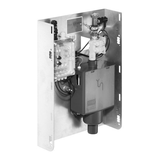
Product information 2 Product information Safety advice DANGER! Danger due to electrical current An electric shock can lead to burns and serious injury and even death. – Work on the electrics may only be carried out by trained electricians. – Switch off the mains voltage before carrying out work on electrical parts. - Page 8 Product information Protective plug at water connection Instructions for use Fig. 1: Overview of flush valve 1 - Flow switch 2 - Magnet valve 3 - floating switch 4 - siphon with integrated overflow monitoring (floating switch) 5 - base support 6 - control Flush valve universal 8 from 62...
- Page 9 Product information Control Fig. 2: Overview of control 1 - Bush (flush command input and event signaling outputs) 2 - Bush (flush command voltage and event signaling output 4-20 mA) 3 - flow switch bush 4 - backflow sensor bush 5 - magnet valves bushes 6 - reset button backflow 7 - test button test flushing...
- Page 10 Product information Magnet valve Fig. 3: Magnet valve overview 1 - fixing flange 2 - magnetic coils 3 - flow control 4 - valve body Flush valve universal 10 from 62...
- Page 11 Product information Flow switch Fig. 4: Flush switch, overview 1 - Flow switch 2 - union nut 3 - T-piece 4 - union nut Flush valve universal 11 from 62...
-
Page 12: Operating Mode
Product information Siphon Fig. 5: Overview siphon 1 - lid 2 - socket 3 - drain with free discharge AB 4 - floating switch 2.3.2 Operating mode The flush valve is intended for automated water exchange (flushing) in the connected drinking water pipelines. The flush valve is suitable for connection to DN 12-80 manifold or riser pipes. - Page 13 Product information Water exchange actuation The following additional or customer-provided components can actuate water exchange (flushing): Timer Building control system (BCS) Furthermore, the flush valve flushes all valves for 10 seconds every 72 hours (time-delayed cycle: 1.5 s open, 1.5 s closed) to prevent blocking of valves and stagnation of the water within the valve.
- Page 14 Product information The flush valve comprises a siphon / odour trap. No addi- tional siphon is required outside of the flush valve. NOTICE! The dimension of the wastewater conduits must comply with the specifications of DIN 1986-100. Flowthrough monitoring During a water exchange, a flow switch checks whether water is dis- charged in the proper manner.
- Page 15 Product information Fig. 6: Connection diagram line L line N PE line fault (alarm) flush command (flushing) water exchange ongoing (flushing ongoing) backflow (fault backflow) flush command (6–48 V AC/DC) flowthrough volume (4–20 mA) 10 - 100–240 V AC Switching the signal outputs The outputs are digital outputs (potencial-free N.O.
-
Page 16: Sound Protection
Product information NOTICE! The maximum load on the binary outputs is 24 V and 1 A (max. 24 W). Do not switch loads directly via the signal out- puts! An analog voltage of 6–48 V AC/DC can be applied at connector 8 to initiate a water exchange. -
Page 17: Technical Data
Product information 2.3.4 Technical data Ambient conditions Operating temperature of the con- 0 °C up to 50 °C trol unit Relative humidity 5 to 95 % (non-condensing) Storage temperature -20 °C up to 80 °C Protection class IP54 Power supply / control Mains voltage 100–240 V ±10 % AC Mains frequency... -
Page 18: Information For Use
0.2 MPa (2 bar) 0.3 – 0.8 MPa (3–8 bar) Information for use 2.4.1 Installation variations Viega front-wall installations Fig. 7: Viega Steptec installation diagram Ä „Viega Steptec“ on page 30 . For mounting, see Flush valve universal 18 from 62... - Page 19 Product information Fig. 8: Viegaswift installation diagram Ä „Viegaswift / Viega Eco Plus“ on page 31 . For mounting, see Flush valve universal 19 from 62...
- Page 20 Product information Fig. 9: Viega Eco Plus installation diagram Ä „Viegaswift / Viega Eco Plus“ on page 31 . For mounting, see Flush valve universal 20 from 62...
- Page 21 Product information Concealing mounting Fig. 10: Installation diagram concealed mounting Ä „Concealing mounting“ on page 32 . For mounting, see Flush valve universal 21 from 62...
- Page 22 Product information Wall mounting Fig. 11: Installation diagram wall mounting Ä „Wall mounting“ on page 32 . For mounting, see Flush valve universal 22 from 62...
-
Page 23: Accessories And Spare Parts
Product information Dry construction Fig. 12: Installation diagram dry construction Ä „Dry construction“ on page 33 . For mounting, see Accessories and spare parts Accessories Product Model Article Cover set 2243.11 735 197 wall mounting Cover set for 2243.12 735 203 concealed mounting Maintenance set... - Page 24 DN 20 Shut-off for con- 2137.09 624 217 cealed mounting, as an alternative: Easytop Basic valve DN 20 Viega Steptec 8437.90, min. 4 pc. 494 179 fasteners Viega Swift/Eco- 8013.23, min. 4 pc., 6 308 278 Plus fastener pc.
-
Page 25: Handling
Handling 3 Handling Transport and storage Note the following for transport and storage: Avoid hard impacts and heavy vibrations. Store the parts in a clean and dry environment. Do not remove the components from the packaging until immedi- ately before use. Use the transport lock as site protection. -
Page 26: Potential Equalisation
Handling 3.2.2 Potential equalisation DANGER! Danger due to electrical current An electric shock can lead to burns and serious injury and even death. Because all metallic piping systems conduct electricity, unintentional contact with a live part can lead to the whole piping system and components connected to it (e. -
Page 27: Installation Dimensions
Handling 3.2.3 Installation dimensions (125) Fig. 13: Flush valve dimensions Flush valve universal 27 from 62... - Page 28 Handling Fig. 14: Dimensions concealed-mounting cover Flush valve universal 28 from 62...
-
Page 29: Mounting
Handling ±0.2 ±0.8 125.2 431.8 ±0.2 71.8 ±0.2 61.3 114.5 ±0.2 ±0.2 Fig. 15: Dimensions of the wall-mounting cover Mounting 3.3.1 Mounting the base Site protection The flush valve is delivered pre-assembled and ready for connection. All components are mounted to the base and have been tested for leak tightness and proper function. - Page 30 To give you a better view, the base is shown as empty for the following assembly steps. Fig. 16: Protective cardboard box, delivery condition Viega Steptec Use Steptec slot nuts model 8437.90 for assembly. Push the slot nuts through the cuttings of the base into the open sides of the mounting rail.
- Page 31 Further see line“ on page 34 . Viegaswift / Viega Eco Plus The base fits exactly on the Viegaswift and the Viega Eco Plus. Use hammer head screws model 8013.23 for assembly. Push the screws through the cuttings of the base into the rail of the basic element.
- Page 32 Handling Align the base using a spirit level. Tighten the nut. Repeat the process for fastening the base at the other side. Ä Chapter 3.3.2 „Connecting the flush valve to the pipe- Further see line“ on page 34 . Concealing mounting Select the fixing material in accordance with the underground.
- Page 33 Handling Align the base using a spirit level. Mark the positions for the dowel holes. Drill holes and insert dowels. Put the base on the dowels and hand-tighten the screws. Align the base once more using a spirit level, and tighten the screws.
-
Page 34: Connecting The Flush Valve To The Pipeline
Handling Use suitable fixing material to fastened the base to the support pro- file. Ä Chapter 3.3.2 „Connecting the flush valve to the pipe- Further see line“ on page 34 . 3.3.2 Connecting the flush valve to the pipeline Installation variants For mounting in a ring installation, mount the flush valve with a main- tenance shut-off directly at the T-piece with the water flow. -
Page 35: Connecting Electrical Components
Handling Connect the supply line (1). Connect the drainage line (2). Up to the next branch into the sewer line, use DN 50 as a minimum. Downstream of the branch, extend width to DN 70 as a minimum, depending on the consumer. There is no need to install another siphon. - Page 36 Handling For safety reasons, pull the mains plug before you open the cover. Control connections Fig. 17: Overview of control Bush (flush command input and event signaling outputs) Bush (flush command voltage and signalling output 4–20 mA) flow switch bush backflow sensor bush magnet valves bushes reset button backflow...
- Page 37 NOTICE! The power pack is intended exclusively for use in closed rooms with the flush valve model 2243.10. Fig. 18: Protected zones according to VDE 0100 part 701 Requirements: A 230 V mains connection is available on site.
- Page 38 Handling Press down the locks at the side one after the other, and push up. Pull the top apart. Unscrew the strain clamp and push on the connection pipeline. Push the top into the connection pipeline. Connect the leads to the terminals. N = blue L = brown or black You do not need a PE conductor.
-
Page 39: Flushing The Valve
Handling The following functions can be set by means of potencial-free contacts: Message: Operating / fault Message: Water exchange ongoing Message: Backflow Message: Active valve runs / setting of flowthrough volumes The maximum length of line is 50 m with 2 x 0.5 mm 3.3.4 Flushing the valve Before commissioning, the system must be flushed according to the... -
Page 40: Manual Functional Test
Handling Re-install the magnet valve with the old seal (SW 30). Note the tight- ening torque of the union nuts: max. 8 Nm. NOTICE! Risk of damage to magnet valve! Do not forget to put the sieve back in again to avoid damage to the valve due to dirt particles! Fill and flush the system. -
Page 41: Notes On Wall Installation
Handling „Throughflow“ lights up. The light of the LEDs goes out in the same sequence. LED "Function" The LED "Function" emits light: Ä Chapter red - Malfunction is pending, e.g. magnet defective, see 3.5.2 „Troubleshooting“ on page 53 . green – Normal operation 3.3.6 Notes on wall installation After mounting, be sure to place the protective cardboard box back... - Page 42 Handling Place the washers on the screw and screw on the wing nuts. Insert the frame between the washer and the base. Tighten the wing nuts. Insert the lid and close it. Wall mounting cover Flush valve universal 42 from 62...
-
Page 43: Commissioning
Handling Put the wall mounting cover on. Fasten the wall mounting cover. Commissioning 3.4.1 Leakage test The qualified craftsman must perform a leakage test (load and leakage test) before commissioning. For example the following regulations apply: DIN EN 806–4 "Leakage tests of drinking water installations with ZVSHK Data sheet compressed air, inert gas or water"... - Page 44 Handling Switching valve flushing on and „3d / 10s“ in the control to position To switch on, set the switch "On". To switch off, return the switch to its original position. Setting the flush volume Specify the flush volume by setting the number of valves which open during flushing, and by the period of time for which the flush command is applied (e.g.
- Page 45 Handling Flowthrough volumes at flow pressure 0.3 MPa (3 bar) Period of Period of Valve Valve Valve Valve time in time in 1 litre 1+2 litres 1-3 litres 1-4 litres minutes seconds 0.75 The flowthrough volumes are defined by the period of time for which the flush command or floating contact is applied, or by analog voltage from the external control.
-
Page 46: Faults, Faults And Remedy
Handling Faults, faults and remedy 3.5.1 Visible faults and LED Indications Faults can be visible in the form of: Leaking water Reactions from connected external sensors Evaluation of the signal outputs in the BCS LED indications at the control Normal operation – standby Flush valve universal 46 from 62... - Page 47 Handling All LEDs emit green light – All functions are operating properly Flush valve universal 47 from 62...
- Page 48 Handling Two red LEDs – backflow Flush valve universal 48 from 62...
- Page 49 Handling Red light now only from top right LED – backflow remedied but Reset has not been pressed / executed Flush valve universal 49 from 62...
- Page 50 Handling All LEDs emit green light – Flush command has been applied, water is flowing Flush valve universal 50 from 62...
- Page 51 Handling Green light now only from one LED each top, right, centre – No flush command, water is flowing Flush valve universal 51 from 62...
- Page 52 Handling Green light only from one bottom LED, red light from 3 LEDs – only one valve / flush section enabled, water is flowing Flush valve universal 52 from 62...
-
Page 53: Troubleshooting
Handling LED "Function" red LED – Fault 3.5.2 Troubleshooting Error Cause Result "Alarm" message No power supply to control Check or establish power supply Magnet valve defective Check magnet valve, replace if applicable Short-circuit at magnet valve Check magnet valve, replace if applicable Check the connection Flush valve universal... - Page 54 Handling Error Cause Result Magnet valve not or not properly Check or establish connection connected Message / indication "Backflow" Water does not run off, drain is Clean the sewer line, remove the clogged cause Sewer line dimensioned too small Adjust the dimension Mount an additional siphon in the Remove the siphon drain downstream of the flush...
-
Page 55: Care And Maintenance
Handling Error Cause Result Insufficient pressure (min. 0.1 MPa (1 bar) flow pressure). Increase pressure Air in the line Vent the line Control defect Check and if applicable replace control Message "Flowthrough (4–20 mA)" Terminal not properly connected Check or establish the connection no signal Connection pipeline too long Length of connection pipeline... -
Page 56: Carrying Out Inspections
Handling 3.6.2 Carrying out inspections Weekly inspection The weekly inspection is required if the flush valve is not connected to a building control system or another higher-level control. Interval once per week Carried out by Skilled technician / instructed user Visually check the control indications. - Page 57 Handling Replacing the sieve Possibly, thorough cleaning of the sieve will be sufficient. CAUTION! Risk of burning due to hot magnetic coils! After prolonged water exchange, the magnet coils get hot. Do not touch them. Shut the water off. De-energise the flush valve. Disconnect the plug from the control.
-
Page 58: Repairing
Handling Checking the flow switch Press the Test button and keep pressed until the indication "Flow switch" emits light (already with 1 valve). Release the Test button. Carry out a test flushing. 3.6.4 Repairing In case of a malfunction, several components may require repairs. In this case, proceed as described in the following: Replacing the floating switch Shut the water off. - Page 59 Handling Disconnect and pull off the connection lines of the floating switch (SW 15). Compress the top of the siphon lid on both sides with your hands. ð The front lock comes off. With your thumb and forefinger, lift the siphon lid by 10–30 mm. 10 - 30 Slightly pull the lifted siphon lid forward.
- Page 60 Handling Lift the siphon lid and disconnect the cables of the floating switch at the lid (1). Check the floating switch (note the indicators) and replace if neces- sary (2). Re-assemble the components in reverse order. Screw down the nut of the floating switch not more than hand-tight. Carry out a test flushing.
- Page 61 Handling Connections Magnet valve coils at the bottom, depending on length Floating switch bottom right side Flow switch centre right side Replacing the flow switch Shut the water off. De-energise the flush valve. Disconnect the plug from the control. Disconnect and remove the connection line of the flow switch. Unscrew the union nut of the flow switch (at the side of the T-piece).
-
Page 62: Care
Handling 3.6.5 Care Clean the components if necessary. Only use a damp cloth. Never use chemicals to clean the device! Disposal Separate the product and packaging materials (e. g. paper, metal, plastic or non-ferrous metals) and dispose of in accordance with valid national legal requirements.
Need help?
Do you have a question about the 2243.10 and is the answer not in the manual?
Questions and answers