
Related Manuals for Viega Easytop 2282


Summary of Contents for Viega Easytop 2282
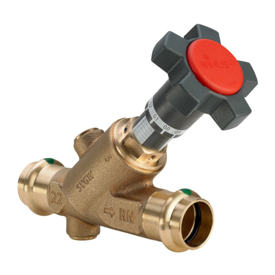
- Page 1 Easytop circulation regulation valve, static regulation valve with SC-Contur Instructions for Use for hydraulic line calibration in drinking water installations Model Year built: 2282 from 11/2011 en_INT...
- Page 2 Easytop circulation regulation valve, static regulation valve with SC-Contur 2 from 25...
-
Page 3: Table Of Contents
Table of contents Table of contents About these instructions for use Target groups Labelling of notes About this translated version Product information Standards and regulations Intended use 2.2.1 Areas of use 2.2.2 Media Product description 2.3.1 Overview 2.3.2 Press connection with SC-Contur 2.3.3 Sealing elements 2.3.4... -
Page 4: About These Instructions For Use
This restriction does not extend to possible operating instructions. The installation of Viega products must take place in accordance with the general rules of engineering and the Viega instructions for use. -
Page 5: About This Translated Version
About these instructions for use About this translated version This instruction for use contains important information about the choice of product or system, assembly and commissioning as well as intended use and, if required, maintenance measures. The information about the products, their properties and application technology are based on the current standards in Europe (e. -
Page 6: Product Information
Product information 2 Product information Standards and regulations The following standards and regulations apply to Germany / Europe and are provided as a support feature. Regulations from section: Fields of application Scope / Notice Regulations applicable in Ger‐ many Planning, execution, operation DIN EN 806, part 1 and maintenance of potable water installations... - Page 7 Product information Regulations from section: Media Scope / Notice Regulations applicable in Ger‐ many Suitability for drinking water Trinkwasserverordnung (TrinkwV) Regulations from section: Product description Scope / Notice Regulations applicable in Ger‐ many Suitability for drinking water Trinkwasserverordnung (TrinkwV) installations Suitability for drinking water DIN 50930-6 installations...
-
Page 8: Intended Use
Intended use Coordinate the use of the model for areas of use and media other than those described with the Viega Service Center. The functionality of the valve is only ensured by professional design and assembly of the complete system. -
Page 9: Product Description
Product information Product description According to the applicable regulations, Easytop system fittings can be used for all types of potable water and are DVGW certified, see Ä „Reg‐ ulations from section: Product description“ on page 7. Their plastic components comply with the KTW recommendation and the require‐ ments pursuant to the applicable regulations. -
Page 10: Sealing Elements
SC-Contur Fig. 2: SC-Contur Viega press connections are equipped with the SC-Contur. The SC- Contur is a safety technology that is certified by the DVGW and ensures that the connection is guaranteed to be leaky in an unpressed state. In this way, unpressed connections are noticed immediately during a leakage test. -
Page 11: Markings On Components
Product information 2.3.4 Markings on components The press connections are marked with a coloured dot. This identifies the SC-Contur, where the test medium would escape in the case of an inadvertently unpressed connection. The model is marked as follows: flow direction indicator dimension DVGW writing setting scale... - Page 12 Product information Target values The required set values can be obtained from the diagrams below. The intermediate values can be set steplessly. Fig. 3: Diagram set values DN15 Easytop circulation regulation valve, static regulation valve with SC-Contur 12 from 25...
- Page 13 Product information Fig. 4: Diagram set values DN20 Easytop circulation regulation valve, static regulation valve with SC-Contur 13 from 25...
-
Page 14: Information For Use
Product information Fig. 5: Diagram set values DN25 Information for use 2.4.1 Corrosion Overground pipelines and fittings in rooms do not normally require external corrosion protection. There are exceptions in the following cases: Contact with aggressive building materials such as nitrite or mate‐ rials containing ammonium in aggressive surroundings If external corrosion protection is required, observe the pertinent guide‐... -
Page 15: Optional Accessories
Product information Optional accessories The following optional accessories are available: Drainage valve Thermometer Insulating shell Fig. 6: Model 2234.6 Easytop drainage valve Fig. 7: Model 1026.6 Easytop thermometer Fig. 8: Model 2210.35, insulating shell EPS insulating shells are available for the static circulation regulation valve. -
Page 16: Handling
Handling 3 Handling Assembly information 3.1.1 Permitted exchange of sealing elements Important instruction With their material-specific qualities, sealing elements in press connectors are adapted for use with the corre‐ sponding media and/or the areas of use of the piping sys‐ tems and are generally only certified for them. -
Page 17: Required Tools
Press jaw or press ring with corresponding hinged adapter jaw, suit‐ able for the pipe diameter and suitable profile Fig. 9: Press jaws Recommended Viega press machines: Pressgun 5 Pressgun Picco Pressgun 4E / 4B... -
Page 18: Assembly
Handling Assembly 3.2.1 Replacing the sealing element Removing the sealing element Do not use pointed or sharp-edged objects to remove the sealing element. These could damage the sealing element or bead. Remove the sealing element from the bead. Inserting the sealing element Insert a new, undamaged sealing element into the bead. -
Page 19: Pressing The Connection
Handling Cut the pipe properly using a pipe cutter or fine-toothed hacksaw. Avoid grooves on the pipe surface. 3.2.3 Pressing the connection NOTICE! Leaky press connections due to pipes being too short If two press connectors are to be mounted onto a pipe without an interval, the pipe must not be too short. - Page 20 Handling Requirements: The pipe end is not bent or damaged. The pipe is deburred. The correct sealing element is in the press connector. EPDM = polished black The sealing element is undamaged. The complete sealing element is in the bead. Push the press connector onto the pipe as far as it will go.
-
Page 21: Installation Position And Settings
Handling Carry out the pressing process. Open and remove the press jaw. ð Connection is pressed. 3.2.4 Installation position and settings Installation position Installation is possible in the riser pipe. If there are multiple riser pipes on the storey during the installation of the thermostatic circulation regulation valve, then every riser pipe must have a circulation regulation valve mounted, see Ä... -
Page 22: Set Valve
Handling Fig. 10: Static CRV in the riser pipe Settings Set the calculated flow values (see Ä „Target values“ on page 12) before commissioning. 3.2.5 Set valve Setting is shown using model 2282 as an example. Before commissioning: Set the valve to the calculated flow value. Easytop circulation regulation valve, static regulation valve with SC-Contur 22 from 25... - Page 23 Handling The set flow quantity can be fixed mechanically. We recommend the fol‐ lowing steps to prevent the set value being adjusted by the opening and closing of the valve: Remove the cover. Mark the position of the handwheel on the spindles. Remove the handwheel.
-
Page 24: Leakage Test
Handling Loosen the screw with the Allen key (SS 2). Screw the adjusting screw (SS 11) into the valve as far as it will go; at the same time, hold the spindle (SS 6) tight. Tighten the screw again with the Allen key (SS 2). Position the handwheel as marked and mount the lid. -
Page 25: Maintenance
Handling Comply with the general rules of engineering and the applicable direc‐ tives, see Ä „Regulations from section: Leakage test“ on page 8. Document the result. Maintenance NOTICE! Inform your customer or the operator of the drinking water installation that the system has to be maintained on a reg‐ ular basis.
Need help?
Do you have a question about the Easytop 2282 and is the answer not in the manual?
Questions and answers