
Subscribe to Our Youtube Channel
Related Manuals for SIKA Type Q


Summary of Contents for SIKA Type Q
- Page 1 DIGITAL PRESSURE GAUGE OPERATING MANUAL Reference Type Q SIKA Dr. Siebert & Kuehn GmbH & Co. KG * Struthweg 7-9 * 34260 Kaufungen * Germany 1/21 Tel +49 5605 803 0 * Fax +49 5605 803 54 * info@SIKA.net * www.SIKA.net...
-
Page 2: Table Of Contents
Product Identification ........................4 Safety Warnings ..........................4 Introduction ............................5 3.1. Technical Description ......................5 Technical Data ..........................6 4.1. Options ............................ 6 Standard Full Scale and Resolution ....................7 Recommended Mechanical Mounting ....................7 6.1. Positioning ..........................7 6.2. - Page 3 Parameters Protected by Password 3124 ................. 17 17.1. Instrument Calibration ......................17 17.2. Calibration Procedure ......................18 17.3. Decimal point ......................... 18 Zero Function..........................19 Peak Function ..........................19 Hold Function..........................19 Serial Communication Commands .................... 20 Maintenance ..........................21 22.1.
-
Page 4: Product Identification
SIKA otherwise won’t be responsible. In particular should be noted that the supplied product is not a safety device. In designing SIKA has taken precautions to minimize risks to user’s safety, but recommends persons who install it the analysis and removal of any residual risks. -
Page 5: Introduction
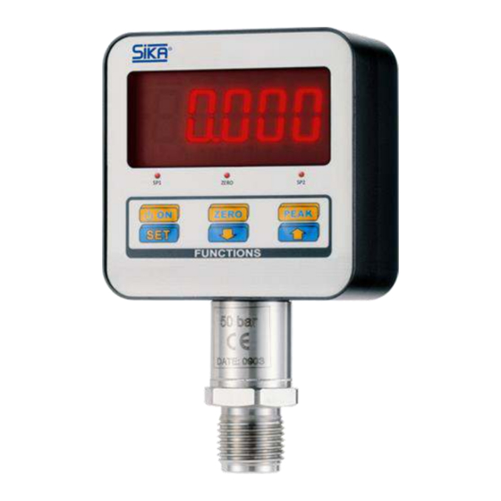
3. I NTRODUCTION The digital pressure gauge Type Q is a 0.15% precision class programmable digital gauge realised with a microcontroller, parameters programming can be done through the keyboard or through the RS232C (on request). Pressure sensor, manufactured on a strain gauge technology, ensures a long term stability. -
Page 6: Technical Data
4. T ECHNICAL RELATIVE PRESSURE 1 - 2.5 - 5 - 10 - 20 bar 50-100-250-350-500-700 bar 1000-1500-2000 bar ±0.15% LINEARITY and HYSTERESIS REFERENCE TEMPERATURE +23C -10… +70°C MAX WORKING TEMPERATURE -20… +80°C STORAGE TEMPERATURE EFFECTS ON A 10°C TEMPERATURE VARIATION ±0.015% a) on zero ±0.005%... -
Page 7: Standard Full Scale And Resolution
5. S TANDARD CALE AND ESOLUTION Nominal Pressure Standard Full Scale Vacuum FS (option) Standard Resolution 1 bar 1.0000 bar -1.0000 0.0001 bar 0,1 mbar 2.5 bar 2.5000 bar -1.0000 0.0005 bar 0,5 mbar 5 bar 5.0000 bar -1.0000 0.0005 bar 0,5 mbar 10 bar 10.000 bar 0.001 bar... -
Page 8: Connections
7. C ONNECTIONS Description Terminal Name Earth protection EARTH Power supply (-) Power supply (+) +12Vdc Power supply (+) +24Vdc RS-232 Receive RS-232 Send RS-232 Common Tension output VOUT Analogue outputs common 19, 21 Current output IOUT Relay 1 common Relay 1 normal open Relay 1 normal close Relay 2 common... -
Page 9: Relay Output Connection
7.3. ELAY UTPUT CONNECTION Max contacts rate (resistive load) 115 VAC, 0.2 A 48 VDC, 0.2 A 100’000 Operations number at specified rating Relay outputs are not protected. It is necessary to externally protect the contacts against the transients which generate in commutation on inductive loads in AC with varistors or RC modules, in DC with varistors or diodes. -
Page 10: Power Supply
8. P OWER UPPLY Fuse Output +12Vdc +12Vdc oppure / or Output +24Vdc Fuse +24Vdc External feeder Pressure gauge Cable length max 3m EARTH EARTH WARNING To ensure the safety rules and the instrument integrity, the feeding input must be protected with a F type 250 mA / 250 V fuse. -
Page 11: Error Messages
9. E RROR ESSAGES UPPER Positive overload. Manometer measures a pressure higher than its nominal rate. LOWER Negative overload. Manometer measures a depression (vacuum) higher than a -1 bar. WARNING After high overloads occurs, check whether calibration has not been changed. Error 1 / Error 2 / Error 4 Error on internal peripheral. -
Page 12: Parameter Programming
11. P ARAMETER ROGRAMMING The instrument can be programmed through the parameter MENU: Set point 1 Hysteresis 1 Set point 2 Hysteresis 2 Password o Protected parameters - password Measurement resolution Digital Filters ... -
Page 13: Parameter Settings
13. P ARAMETER ETTINGS 13.1. MENU OW TO GET ACCESS TO THE In the main page (pressure indication) press MENU key - on the display the string “SP1 P” appears, this is the first parameter in the menu. Press ENTER to display the parameter value associated to “SP1 P”. -
Page 14: Hysteresis 2
14.4. YSTERESIS Calculate the set point deactivation value. Deactivation value = (SP2 value – Hysteresis2 value). Relay R2 and the LED corresponding to SP2 are disabled. 0000…9999 Selectable values (NNNN) 14.5. ASSWORD A Password is required to get access to the following MENU ... -
Page 15: Parameters Protected By Password 0007
15. P 0007 ARAMETERS ROTECTED BY ASSWORD 15.1. EASUREMENT ESOLUTION This function enables the operator to define the variation of the last two digits. This system is implemented to increase measurement stability in dynamic application at the expense of reading accuracy. Selectable values 1 / 2 / 5 / 10 / 20 / 50 / 100 15.2. -
Page 16: Analogue Output
15.5. NALOGUE UTPUT Selecting Y+ENTER operator accesses to analogue output parameters. Selecting n+ENTER, the operator jumps to the next parameter. Selectable outputs Disab = disabled (about 0 V) P 10 = +10 V Pn 10 =+/-10 V 0-20 = 0…20 mA 4-20 = 4…20 mA Notes: The analogue output varies proportionally to analogue output full scale, the maximum resolution is 15 bits for all outputs;... -
Page 17: Parameters Protected By Password 4256
WARNING This procedure must be performed by authorized Calibration Center only and in case of real need only. SIKA declines any responsibility for measurements errors or bad functioning caused by calibrations performed not correctly which make lose certification on manometer as well. -
Page 18: Calibration Procedure
17.2. ALIBRATION ROCEDURE Enter into the protected menu by pressing SET, then press ENTER until “PASSW” is shown, press ENTER to get access to the password setting, set “3124” to enable the manometer calibration, press ENTER to confirm. “P0” parameter will appear. P0 (zero point) Set the manometer at zero pressure by opening the hydraulic circuit, confirm through ENTER, the manometer shows an internal offset value, set to zero by pressing ZERO,... -
Page 19: Zero Function
18. Z UNCTION The ZERO function is used to set the instrument indication to zero. The displayed value of the instrument, before function activation, will be deducted from measured value, the result (0) is showed on the display. The function acts on the entire measurement range (100%). -
Page 20: Serial Communication Commands
21. S ERIAL OMMUNICATION OMMANDS The serial communication is made through reading and writing commands in ASCII codes. When a command is recognized, then the instrument answers with the string: $ II ACK <cr> ASCII CHAR $(36 ) String beginning 00 ASCII CHAR $(48)$(48) Identification Number ASCII CHAR $(6) Recognized command... -
Page 21: Maintenance
SIKA Dr. Siebert & Kuehn GmbH & Co. KG * Struthweg 7-9 * 34260 Kaufungen * Germany 21/21...
Need help?
Do you have a question about the Type Q and is the answer not in the manual?
Questions and answers