Advertisement
Quick Links
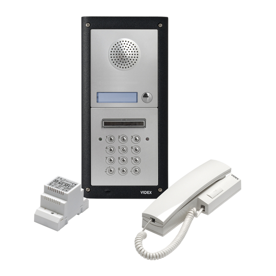
DK4K-1
DK4K-1S
GENERAL DIRECTIONS FOR INSTALLATION
In order to achieve the best results from the schematics described it is
necessary to install only original
the items indicated on each schematic and follow these General
Directions for Installation:
!
The system must be installed according to national rules in force, in
any case the running of cables of any intercom unit must be carried
out separately from the mains (see the next paragraph for
connection to mains and power supply installation);
!
All multipair cables should be compliant to CW1308 specification
(0.5mm twisted pair telephone cable.
!
Cables for speech line and service should have a max resistance of
W
10
!
Lock release wires should be doubled up (Lock release wires and
power supply wires should have a max resistance of 3 );
!
The cables sizes above can be used for distances up to 50m. On
distances above 50m the cable sizes should be increased to keep
the overall resistance of the cable below the RESISTANCES
indicated above;
!
Double check the connections before power up;
!
Power up the system then check all functions.
CONNECTION TO MAINS AND
POWER SUPPLY MOUNTING INSTRUCTIONS
The system must be installed according to national rules in force, in
particular we recommend to:
·
Connect the system to the mains through an
breaker
which shall have contact separation of at least 3mm in each
pole and shall disconnect all poles simultaneously;
·
The
all-pole circuit breaker
switch shall remain readily operable.
Power Supply Installation
-
Remove the terminal side covers by unscrewing the retaining
screws;
-
Fix the power supply to a DIN bar or directly to the wall using two
expansion type screws;
-
Switch off the mains using the circuit breaker mentioned above and
then make the connections as shown on the installation diagrams;
-
Check the connections and secure the wires into the terminals;
-
Replace the terminal covers and fix them using the relevant screws;
-
When all connections are made, restore the mains.
LOCK RELEASE BACK EMF PROTECTION
A capacitor must be fitted across the terminals on AC lock release
(Fig.1A) and a diode must be fitted across the terminals on a DC lock
release (Fig.1B) to suppress back EMF voltages. Connect this
components to the lock releases as shown in figures.
Installation Instructions
Istruzioni di Installazione
VIDEX
equipment, strictly keeping to
W
all-pole circuit
shall be placed for easy access and the
Fig.1A
NORME GENERALI D'INSTALLAZIONE
Per eseguire una corretta installazione è necessario impiegare
esclusivamente parti
VIDEX
negli schemi di collegamento e tenere presenti le norme generali
d'installazione:
!
Realizzare gli impianti secondo le vigenti normative nazionali ed in
ogni caso si consiglia di prevedere, per i conduttori dell'impianto,
una canalizzazione distinta da quella della linea elettrica (vedi
paragrafo seguente per il collegamento alla linea elettrica e
l'installazione dell'alimentatore);
!
Impiegare conduttori con sezioni tali da avere:
>
resistenza complessiva inferiore a 10
fonica e di comando;
>
resistenza complessiva inferiore a 3 per quelli della serratura
e di alimentazione;
!
Verificare le connessioni prima di dare alimentazione all'impianto;
!
Alimentare l'impianto ed eseguire il collaudo verificandone tutte le
funzioni.
COLLEGAMENTO ALLA RETE ELETTRICA ED
INSTALLAZIONE DELL'ALIMENTATORE
La realizzazione dell'impianto deve essere eseguita nel rispetto delle
vigenti normative nazionali, in particolare si raccomanda di:
·
Collegare l'impianto alla rete elettrica tramite un
interruzione omnipolare
del contatto di almeno 3mm per ciascun polo e che sia in grado di
disconnettere tutti i poli simultaneamente;
·
Il
dispositivo di interruzione omnipolare
in un luogo tale da consentirne un facile accesso in caso di
necessità.
Installazione dell'alimentatore
-
Rimuovere i coperchi copri-morsetti svitando le relative viti e
tirandoli verso l'alto;
-
Fissare l'alimentatore su barra DIN o direttamente a parete
utilizzando le viti ed i relativi tasselli ad espansione forniti a corredo;
-
Togliere la tensione di rete tramite il dispositivo sopra indicato ed
eseguire le connessioni come previsto dagli schemi proposti (la
connessione verso la rete va effettuata in base alla tensione
disponibile 127 o 230Vac).
-
Verificare che non vi siano errori di connessione e che i fili siano ben
serrati nei morsetti;
-
Inserire a scatto i coperchi copri-morsetti e fissarli tramite le relative
viti;
-
Eseguiti tutti i collegamenti, dare tensione all'impianto.
AZIONAMENTO SERRATURA- PROTEZIONE DAI DISTURBI
L'azionamento della serratura elettrica può provocare degli spike, per
evitare tale inconveniente si consiglia di collegare tra i terminali della
serratura un condensatore (Fig.1A) o un diodo (Fig.1B) a seconda
che la serratura sia in alternata o in continua.
, seguire con scrupolo quanto indicato
W
per quelli della linea
W
dispositivo di
che abbia una distanza di separazione
deve essere posizionato
Fig.1B
Advertisement

Related Manuals for Videx DK4K-1S


Summary of Contents for Videx DK4K-1S
- Page 1 DK4K-1 Installation Instructions DK4K-1S Istruzioni di Installazione GENERAL DIRECTIONS FOR INSTALLATION NORME GENERALI D’INSTALLAZIONE In order to achieve the best results from the schematics described it is Per eseguire una corretta installazione è necessario impiegare necessary to install only original...
-
Page 2: Installazione Posto Esterno
INSTALLAZIONE POSTO ESTERNO INSTALLING OUTDOOR STATION Fig.1 Fig.2 Fig.3 Fig.4 Fig.5 Fig.6 Fig.7 Fig.8 Fig.9... - Page 3 INSTALLING OUTDOOR STATION INSTALLAZIONE POSTO ESTERNO SURFACE DOOR STATION (DK4K-1S) POSTO ESTERNO DA SUPERFICIE (DK4K-1S) Place the surface box against the wall (165-170cm between Appoggiare la scatola da incasso alla parete (ci devono the top of the box and the floor level as shown in figure 1) and...
- Page 4 Factory - Office (All Countries Support) VIDEX ELECTRONICS S.p.A . Via del lavoro,1 63020 MONTEGIBERTO (AP) - ITALY Phone: (+39) 0734 - 631669 Fax: (+39) 0734 - 632475 www.videx.it e-mail: info@videx.it Northern UK Office (Only UK Support) VIDEX LTD Unit 5-7 Chillingam Industrial Estate Chapman Street NEWCASTLE UPON TYNE Ne6 2XX...
- Page 5 In order to achieve the best results from the schematics described it is Per eseguire una corretta installazione è necessario impiegare necessary to install only original VIDEX equipment, strictly keeping to the esclusivamente parti VIDEX, seguire con scrupolo quanto indicato negli...
- Page 6 PROGRAMMING (SEE ALSO THE RELEVANT FLOW CHART) PROGRAMMAZIONE (VEDI RELATIVO DIAGRAMMA DI FLUSSO) - Enter the “MASTER CODE”: first time type six times “1” (111111 factory - Digitare il “MASTER CODE”: 6 volte “1” (111111 impostazione di preset) and press “ENTER” (The red LED will illuminate); fabbrica) e premere “ENTER”...
- Page 7 TERMINALS: MORSETTIERA: Relay 2 command signal (active low) Comando d’abilitazione del relé 2 (ingresso attivo basso) Comando d’abilitazione del relé 1 (ingresso attivo basso) Relay 1 command signal (active low) Relay 3 normally closed contact Relé 3 contatto normalmente chiuso Relay 3 normally open contact Relé...
- Page 8 CUSTOMER SUPPORT INFORMATION INFORMAZIONI ASSISTENZA CLIENTI All Countries Customers UK Customers Clienti di tutti i Paesi Clienti UK VIDEX Electronics S.p.A. VIDEX Security LTD VIDEX Electronics S.p.A. VIDEX Security LTD www.videx.it – technical@videx.it www.videx-security.com www.videx.it – technical@videx.it www.videx-security.com Tel.+39 0734 631669 Tech Line 0191 224 3174 Tel.+39 0734 631669...
Need help?
Do you have a question about the DK4K-1S and is the answer not in the manual?
Questions and answers