Advertisement
Quick Links
Applied Machines: C754/C654/C554/C454/C364/C284/C224
COLOR MFP: 75 ppm/65 ppm/55 ppm/45 ppm/36 ppm/28 ppm/22 ppm
Product Code: A2X0/A2X1/A2XK/A4FJ/A161/A4FK/A4FM
Caution:
Lifting the machine in an awkward position or
transporting it in a poorly balanced position could
result in personal injury. When transporting the
machine, assign an adequate number of persons
to the job and ensure that each person can take a
good position of not being excessively loaded.
(mass: approx. 40 kg (88-3/16 lb))
I. Accessory parts
No.
Name
1. Horizontal
transport unit
2. Sensor unit
*2
3. Exit tray (upper)
4. Exit tray (lower)
5. Staple cartridge
6. Mounting
*1
bracket A
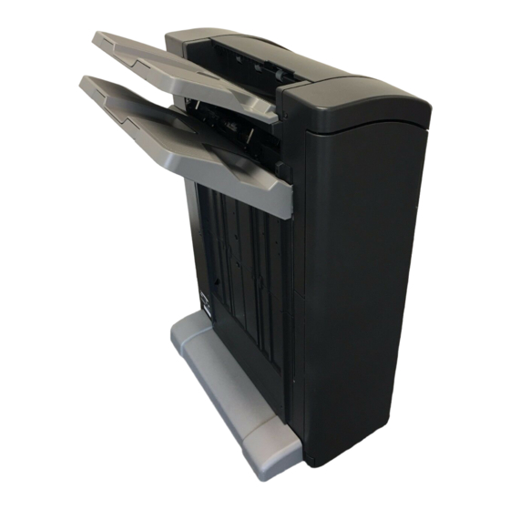
FS-534
INSTALLATION MANUAL
Shape
Q'ty
1
A3EPIXC001DA
1
A2YVIXC002DA
1
A3EPIXC002DA
1
A3EPIXC003DA
1
A3EPIXC004DA
1
A3EPIXC005DA
Finisher
No.
Name
7. Mounting
*1
bracket B
8. Mounting
*2
bracket C
9. Mounting
*2
bracket D
10. Mounting
*2
bracket E
11. Mounting
bracket F
12. Mounting
bracket G
13. Guide plate A
*1
14. Guide plate B
*1
15. Wire saddle
*2
E-1
Shape
Q'ty
1
A3EPIXC006DA
1
A3EPIXC007DB
1
A3EPIXC008DB
1
A3EPIXC009DA
1
A3EPIXC051DA
1
A3EPIXC052DA
1
A3EPIXC010DA
1
A3EPIXC011DA
1
A3EPIXC055DA
A3EP-9550-02
Advertisement

Subscribe to Our Youtube Channel
Related Manuals for Konica Minolta FS-534


Summary of Contents for Konica Minolta FS-534
- Page 1 FS-534 Finisher INSTALLATION MANUAL Applied Machines: C754/C654/C554/C454/C364/C284/C224 COLOR MFP: 75 ppm/65 ppm/55 ppm/45 ppm/36 ppm/28 ppm/22 ppm Product Code: A2X0/A2X1/A2XK/A4FJ/A161/A4FK/A4FM Caution: Name Shape Q’ty Lifting the machine in an awkward position or 7. Mounting transporting it in a poorly balanced position could result in personal injury.
- Page 2 Note: Name Shape Q’ty • Before installing this finisher to C554/C454/ 16. Mounting screw C364/C284/C224, the paper feed cabinet PC- 110, PC-210, PC-410, or the desk DK-510 needs to be installed in advance. • This manual provides the illustrations of the A0HRIXC011DA 17.
- Page 3 III. Installation procedures 5. Attach the mounting bracket G to the mounting bracket B. (One supplied screw D) Note: The parts to be used and the procedure for install- ing this option depend on the type of the main unit to which this option is installed.
- Page 4 8. Remove the cover shown in the illustration. 11. Attach the guide plate B. (Two screws removed (Three screws) in step 9) A3EPIXC039DA A3EPIXC042DA 9. Remove the cover shown in the illustration from 12. Attach the supplied mounting bracket A (front) to the front of the horizontal transport unit.
- Page 5 <When installing this option to C554/C454/C364/ 14. Remove one knockout (front) from the lower left side of the main unit with nippers. C284/C224> 1. Turn off the machine and unplug the power cord from the power outlet. 2. Remove the user’s guide holder from the main unit.
- Page 6 6. Reattach the upper left cover removed in step 4 11. Peel the seal off the cover removed in step 9 as to the main unit. (Three screws) shown in the illustration. 7. Close the front door of the main unit. 8.
- Page 7 14. Connect the sensor unit’s connector to the con- 17. Attach the mounting bracket G to the mounting nector of the harness removed in step 10. bracket D. (One supplied screw D) A2YVIXC013DA A3EPIXC054DB 15. Route the harness through the two wire saddles 18.
- Page 8 21. Attach the supplied mounting bracket D (rear). 24. Remove the protective tape and the protective (Two supplied screws C) materials from the finisher. A3EPIXC016DA A3EPIXC049DA 22. Attach the supplied mounting bracket E to the left side bottom of the main unit. (One supplied screw C) Mounting bracket E A3EPIXC050DA...
- Page 9 27. Remove the protective tape. 31. Attach the supplied exit tray (lower) to the fin- 28. Remove the screw shown in the illustration and isher. (Two supplied screws A) remove the label from the finisher. Label A3EPIXC023DA A3EPIXC020DB 32. Insert the supplied exit tray (upper) into the fin- 29.
- Page 10 36. Verify items ➀ and ➁ below. 34. Open the finisher front door and pull the lever. ➀ The plate spring of the plate installed in step 30 is contacted with the main unit. ➁ When the lever that was pulled out in step 34 is pushed back, the finisher’s screw hole is within the range of lever’s mounting hole.
- Page 11 (1) Disconnect the connector, and remove the fin- (4) Adjust the height of the four casters. isher from the main unit. A3EPIXC029DC (2) Remove the cover from the caster of the fin- isher. (Two screws) A3EPIXC032DA (5) Double check the verification items ➀ and ➁. If there are any problems, go back to (4) and readjust the caster height.
- Page 12 39. Remove the cover shown in the illustration from 40. Plug in the two connectors of the finisher. Fit the the back of the main unit. (One screw) head of the cable tie into the mounting hole on the main unit. <When installing this option to C754/C654>...
- Page 13 42. Reattach the cover removed in step 39. (One screw) Note: • Be careful not to pinch the harness. • When installing this option to C554/C454/C364/ C284/C224, insert two tabs A into the holes on the main unit cover first. Then fit two tabs B into the holes.
Need help?
Do you have a question about the FS-534 and is the answer not in the manual?
Questions and answers