Advertisement
Quick Links
Caution:
Lifting the machine in an awkward position or
transporting it in a poorly balanced position could
result in personal injury. When transporting the
machine, assign an adequate number of persons
to the job and ensure that each person can take a
good position of not being excessively loaded.
(mass: approx. 23 kg (50-11/16))
I. Accessory parts
No.
Name
1. Exit tray
2. Exit tray cover
3. Exit lever
4. Guide plate
5. Rail (Right)
without hook
6. Rail (Left)
with hooks
7. Screw
SD-511
INSTALLATION MANUAL
Shape
Q'ty
1
A3ERIXC001DA
1
A3ERIXC002DA
1
A3ERIXC003DA
1
A3ERIXC004DA
1
A3ERIXC005DA
1
A3ERIXC006DA
6
9654
Saddle Stitcher
No.
Name
8. Installation
manual
After unpacking, be sure to get rid of the
packaging materials and keep them out of
the reach of children.
Putting the head in the plastic bag
involves danger of suffocation.
Note:
This manual provides the illustrations of the acces-
sory parts and machine that may be slightly different
in shape from yours. In that case, instead of the
illustrations, use the appearance of your machine to
follow the installation procedure. This does not
cause any significant change or problem with the
procedure.
E-1
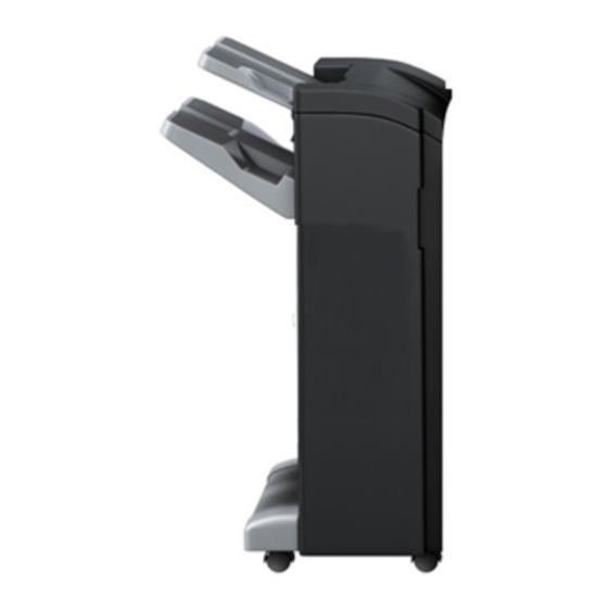
Applied Machine: FS-534
Shape
Q'ty
1
set
4980IXC019DA
A3ER-9550-00
Advertisement

Related Manuals for Konica Minolta SD-511


Summary of Contents for Konica Minolta SD-511
- Page 1 SD-511 Saddle Stitcher INSTALLATION MANUAL Applied Machine: FS-534 Caution: Name Shape Q’ty Lifting the machine in an awkward position or 8. Installation transporting it in a poorly balanced position could manual result in personal injury. When transporting the machine, assign an adequate number of persons to the job and ensure that each person can take a good position of not being excessively loaded.
-
Page 2: Installation Procedures
II. Installation procedures 4. Using the pin removed in step 3, attach the exit lever to the supplied exit tray cover. Note: Note: When mounting the saddle stitcher, mount it Make sure that the pin is fully inserted into the before mounting the finisher to the machine. - Page 3 8. If the stapler unit is positioned toward the front of 11. Open the guide plate and attach the C-clip the finisher, move it to the rear turning the dial removed in step 9. shown in the illustration. Dial A3ERIXC010DA 9.
- Page 4 14. Attach the supplied left and right rails. (two supplied screws each) Note: • Align the end of the rail with the front end of the plate of the finisher. • Put the rail along downward to screw. < Left > <...
- Page 5 16. Pull the left rail out completely from the finisher. 17. Hold the area of the saddle unit shown in the illustration with one of your hands and lift it. Hold the left rail with your other hand. Fasten the saddle unit to the left rail by fitting the tab on the rail into the slot located on the rear side of the saddle unit and then the other tab into the slot on the front side by slightly bending the front side of the rail.
- Page 6 18. Pull the right rail out completely and fit the boss 20. Remove the screw shown in the illustration from of the saddle unit into the positioning hole on the the front of the saddle unit. rail. Caution: Be careful not to hurt yourself while pulling the rail out.
- Page 7 III. Adjustments 23. Secure the pantograph. (one screw removed in step 21) If each mode are out of specifications, make the following adjustments. 1. Select Finishing → Fold/Bind. 2. Make copies in finisher mode and check the sta- tus of the Half-Fold, Center Staple & Fold and Tri- fold.
- Page 8 2. Check the crease for deviation 5. Incline the guide plate assy shown in the illustra- (Measure width A1 and A2). tion and adjust the skew. Reference: A1 - A2 = 0 ± 1.0 mm Note: Incline the guide plate assy forward or backward Crease according to the deviation of the crease.
- Page 9 <Half-fold position adjustment> 4. Display the Service Mode screen. (For details of how to display the Service Mode 1. Unfold the paper that exits the machine and lay screen, see the Service Manual.) the paper with the ridge facing up. 5.
- Page 10 <Center staple position adjustment> [If the Staple positions deviate as shown below] 1. Unfold the paper that exits the machine and lay Using the key, set the numeric value and the paper with the ridge facing up. touch “OK.” Exit direction A10DIXC051DA A10DIXC054DA 2.
- Page 11 <Tri-fold position adjustment> Second fold position adjustment First fold position adjustment 1. Display the Service Mode screen. (For details of how to display the Service Mode 1. Check the width of the first fold position “a.” screen, see the Service Manual.) 2.
Need help?
Do you have a question about the SD-511 and is the answer not in the manual?
Questions and answers