Chapters
Table of Contents

Related Manuals for Stahl is1+ 9442/35 Series


Summary of Contents for Stahl is1+ 9442/35 Series
- Page 1 Betriebsanleitung Operating instructions Additional languages www.r-stahl.com DE EN CPU-Modul für Zone 2 CPU module for Zone 2 Reihe 9442/35 Series 9442/35...
- Page 3 Betriebsanleitung Additional languages www.r-stahl.com CPU Modul für Zone 2 Reihe 9442/35...
-
Page 4: Table Of Contents
Inhaltsverzeichnis Allgemeine Angaben ...................3 Hersteller ......................3 Zu dieser Betriebsanleitung ................3 Weitere Dokumente ....................3 Konformität zu Normen und Bestimmungen ............3 Erläuterung der Symbole ..................4 Symbole in der Betriebsanleitung ...............4 Symbole am Gerät ....................4 Sicherheit ......................5 Bestimmungsgemäße Verwendung ..............5 Qualifikation des Personals ................5 Restrisiken ......................6 Transport und Lagerung ..................8 Produktauswahl, Projektierung und Modifikation ..........8... -
Page 5: De De De
Betriebsanleitung während der Lebensdauer des Geräts aufbewahren. Betriebsanleitung dem Bedien- und Wartungspersonal jederzeit zugänglich machen. Betriebsanleitung an jeden folgenden Besitzer oder Benutzer des Geräts weitergeben. Betriebsanleitung bei jeder von R. STAHL erhaltenen Ergänzung aktualisieren. ID-Nr.: 264707 / 944260310010 Publikationsnummer: 2017-12-01·BA00·III·de·00... -
Page 6: Erläuterung Der Symbole
Erläuterung der Symbole Erläuterung der Symbole Symbole in der Betriebsanleitung Symbol Bedeutung Hinweis zum leichteren Arbeiten GEFAHR! Gefahrensituation, die bei Nichtbeachtung der Sicherheitsmaßnahmen zum Tod oder zu schweren Verletzungen mit bleibenden Schäden führen kann. WARNUNG! Gefahrensituation, die bei Nichtbeachtung der Sicherheitsmaßnahmen zu schweren Verletzungen führen kann. -
Page 7: Sicherheit
Normen und Bestimmungen umfasst. Für Tätigkeiten in explosionsgefährdeten Bereichen sind weitere Kenntnisse erforderlich! R. STAHL empfiehlt einen Kenntnisstand, der in folgenden Normen beschrieben wird: • IEC/EN 60079-14 (Projektierung, Auswahl und Errichtung elektrischer Anlagen) • IEC/EN 60079-17 (Prüfung und Instandhaltung elektrischer Anlagen) •... -
Page 8: De 3.3 Restrisiken
Umgebungsbedingungen (siehe Kapitel "Technische Daten") berücksichtigen. Gerät nicht belasten. Verpackung und Gerät auf Beschädigung prüfen. Beschädigungen umgehend an R. STAHL melden. Beschädigtes Gerät nicht in Betrieb nehmen. Gerät in Originalverpackung, trocken (keine Betauung), in stabiler Lage und sicher vor Erschütterungen lagern. - Page 9 Nur kompatible Komponenten anschließen (Remote I/O System IS1+/IS1). Im Zweifelsfall Rücksprache mit R. STAHL halten. Reparaturen am Gerät nur durch R. STAHL durchführen lassen. Gerät nur mit feuchtem Tuch und ohne kratzende, scheuernde oder aggressive Reinigungsmittel oder Lösungen schonend reinigen.
-
Page 10: De Transport Und Lagerung
Transport und Lagerung 3.3.2 Beschädigung elektrischer Komponenten Empfindliche elektronische Bauteile können durch elektrostatische Entladung (ESD) beschädigt werden. Vor dem Kontakt mit dem Gerät an einem geerdeten metallischen Körper entladen. Direkte Berührung von Steckverbindern oder Kontakten der Modulsteckplätze vermeiden. ... -
Page 11: Sub-D-Buchse X1
Produktauswahl, Projektierung und Modifikation Sub-D-Buchse X1 Für den Anschluss des primären Busses an PROFIBUS DP. 12224E00 Anschlussbelegung: Pin-Nr. Funktion Beschreibung RxD/TxD (+) Daten B (+) Bezugspotential für Geräteschnittstelle PWR (+) Versorgungsspannung (Gerät) RxD/TxD (-) Daten A (-) übrige Pins – nicht angeschlossen RJ45-Buchsen X2 Für den Anschluss des primären und des sekundären Netzwerks Modbus TCP / Ethernet/IP... -
Page 12: De De
Montage und Installation Redundanz Das IS1+ Remote I/O-System kann je nach Applikation auch redundant ausgeführt werden. Dabei wird zwischen CPU-, Power- und System-/Vollredundanz unterschieden. Auswahl des geeigneten Sockels 9496/35 und die maximale Bestückung der CPU Module 9442/35 und Power Module 9445/35 beachten! Folgende Tabelle zeigt die benötigten Komponenten für die jeweiligen Redundanzkonzepte: Sockel 9496/35 CPU Modul 9442/35... -
Page 13: Austausch Und Upgrade Des Moduls
Montage und Installation 6.1.2 Montage auf Sockel 9496/35 Vor der Montage des CPU-Moduls die Bus-Adresse am Sockel einstellen (siehe Betriebsanleitung Sockel 9496/35). GEFAHR! Explosionsgefahr durch unzureichende Befestigung! Nichtbeachten führt zu tödlichen oder schweren Verletzungen. CPU-Modul mit Sicherungsschrauben befestigen, dazu einen Schraubendreher (Innensechsrund T20) verwenden. -
Page 14: De 6.3 Installation
Montage und Installation 6.2.2 Upgrade der IS1 PROFIBUS CPM Reihe 9440/15 auf die IS1+ Kommunikationsbaugruppe CPU 9442/35 + Power-Modul 9445/35 + Sockel 9496/35 Stromversorgung der IS1 Remote I/O-Station (CPM 9440/15) abschalten. Anschlussleitungen für Kommunikation trennen. Blauen Rasthebel der CPM 9440/15 nach oben ziehen, um Modul zu entriegeln. ... - Page 15 Montage und Installation 6.3.1 Feldbus anschließen 19635E00 Primäre Feldbus-Leitung mit Sub-D Stecker an Sub-D Buchse X1 anschließen. Sub-D Stecker mit Schrauben gegen Lockern sichern. Anzugsdrehmoment 0,5 bis 0,6 Nm.. Anschlussleitung gegen Zugbelastung und Scheuern sichern. Der Schirm des Feldbusses muss mindestens an einer Stelle mit dem Potentialausgleich verbunden werden.
-
Page 16: De Parametrierung Und Inbetriebnahme
Parametrierung und Inbetriebnahme Parametrierung und Inbetriebnahme Vor Inbetriebnahme folgende Prüfschritte durchführen: Vorschriftsmäßige Montage und Installation des Gerätes. Korrekter, fester Anschluss der Anschlussleitungen. Keine Schäden am Gerät und an den Anschlussleitungen. Fester Sitz der Befestigungs- und Sicherungsschrauben. ... -
Page 17: Fehlerbeseitigung
Betrieb Fehlerbeseitigung Fehler Status Fehlerursache Fehlerbehebung LED "PWR" Normalbetrieb Kein Fehler – leuchtet LED "PWR" und Software-Update Kein Fehler Ende des Software- "M/S" blinken Updates abwarten LED "PWR" keine Funktion Stromversorgung des • Korrekten Anschluss erloschen CPU-Moduls gestört und intakte Beschaf- fenheit des Power- Moduls prüfen (siehe Betriebsanleitung... - Page 18 Betrieb Fehler Status Fehlerursache Fehlerbehebung LED "M/S" Software-Update Software-Update wird Ende des Software- blinkt durchgeführt Updates abwarten LED "M/S" Kein Wartungs- Kein Fehler – erloschen bedarf LED "AS EXCH" Normalbetrieb Kein Fehler – leuchtet LED "AS EXCH" – CPU inaktiv –...
-
Page 19: Instandhaltung, Wartung, Reparatur
Ausfallwahrscheinlichkeit an (siehe Kapitel "Anzeigen" und "Fehlerbeseitigung"). Gerät gemäß den geltenden nationalen Bestimmungen und den Sicherheitshinweisen dieser Betriebsanleitung (Kapitel "Sicherheit") warten. Reparatur Reparaturen am Gerät nur durch R. STAHL durchführen lassen. 264707 / 944260310010 CPU Modul für Zone 2 2017-12-01·BA00·III·de·00... -
Page 20: 10 Rücksendung
Rücksendung Rücksendung Rücksendung bzw. Verpackung der Geräte nur in Absprache mit R. STAHL durchführen! Dazu mit der zuständigen Vertretung von R. STAHL Kontakt aufnehmen. Für die Rücksendung im Reparatur- bzw. Servicefall steht der Kundenservice von R. STAHL zur Verfügung. -
Page 21: Anhang A
Anhang A Anhang A 14.1 Technische Daten Explosionsschutz Global (IECEx) IECEx PTB 17.0031X Ex ec ia [ia Ga] IIC T4 Gc Europa (ATEX) PTB 17 ATEX 2019 X E II 3 (1) G Ex ec ia [ia Ga] IIC T4 Gc Bescheinigungen und Zulassungen Bescheinigungen IECEx, ATEX... - Page 22 Anhang A Technische Daten Lichtwellen- 2000 m bei 1,5 Mbit/s leiter (mit LWL-Feldbus-Trennübertrager 9186, siehe Zubehör) Max. ( 30 V DC Spannung U Schnittstelle Ethernet Anschluss 2 x RJ45 Stecker, 100BASE-TX, Unmanaged Switch Funktion Protokolle Modbus TCP (PROFINET, Ethernet/IP in Vorbereitung) (vom Anwender über Drehschalter am Sockel 9496/35 wählbar) IP-Adress- via Webserver oder IS1+ Detect Software (Default 192.168.1.101)
- Page 23 Hersteller, Typ, HW-Revision, SW-Revision, Seriennummer Parameter Anschließbare • IS Wizard (über USB Service Bus) Softwarepakete • R. STAHL Geräte DTM mit fdt-Frames (z.B. fdtContainer von M+M; Pactware) • AMS von Emerson Process Management • PDM von Siemens • PRM und Fieldmate von Yokogawa •...
- Page 24 CPU Modul mit Sockel: L = 167 mm, B = 96 mm, H = 152 mm Montage / Installation Einbaubedingungen Montageart auf Sockel 9496/35 Einbaulage waagrecht oder senkrecht Weitere technische Daten, siehe www.r-stahl.com. CPU Modul für Zone 2 264707 / 944260310010 Reihe 9442/35 2017-12-01·BA00·III·de·00...
-
Page 25: Anhang B
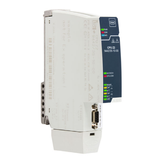
Anhang B Anhang B 15.1 Maßangaben / Befestigungsmaße Maßzeichnungen (alle Maße in mm [Zoll]) – Änderungen vorbehalten 183 [7,20] 158 [6,22] 19668E00 CPU-Modul 9442/35 185 [7,28] 167 [6,57] 19670E00 CPU-Modul 9442/35 mit Sockel 9496/35 264707 / 944260310010 CPU Modul für Zone 2 2017-12-01·BA00·III·de·00 Reihe 9442/35... - Page 26 Anhang B 15.1.1 Geräteaufbau Gerätelement Beschreibung Schraube Innen- sechsrundschraube Größe T20 zum Befes- tigen am Sockel LEDs Status- bzw. Fehler- anzeige der CPU LEDs Status- bzw. Fehler- anzeige der Kommunikation zum Automatisierungs- system LEDs Statusanzeige der 19622E00 Schnittstellen RS 485 Buchse Sub-D Buchse X1 Pro- zessbus, primär Schutzkappe Schutz und Zugent-...
-
Page 27: Anhang C
Anhang C 16.1 Garantie und Haftungsausschluss für Open Source Software der GPL/LGPL Die IS1+ 9442 CPUs der R. STAHL Schaltgeräte GmbH (im folgenden R. STAHL) enthalten neben proprietärer Software auch Bestandteile an "Open Source Software". Die Open Source Software wird Ihnen unter den Bedingungen der GNU General Public License (GPL) und der GNU Lesser General Public License (LGPL) ohne Lizenzgebühren zur Verfügung... - Page 28 Operating instructions Additional languages www.r-stahl.com CPU module for Zone 2 Series 9442/35...
- Page 29 Contents General Information ....................3 Manufacturer .......................3 About these operating instructions ..............3 Further documents ....................3 Conformity with standards and regulations ............3 Explanation of the symbols .................4 Symbols in these operating instructions .............4 Symbols on the device ..................4 Safety ........................4 Intended Use .......................5 Personnel qualification ..................5 Residual risks ......................5 Transport and storage ..................7...
-
Page 30: En En En
Conformity with standards and regulations • Certificates and EU Declaration of Conformity: www.r-stahl.com. • The device has IECEx approval. See IECEx homepage: http://iecex.iec.ch/ • Further national certificates can be downloaded via the following link: https://r-stahl.com/ en/global/products/support/downloads/. 264707 / 944260310010 CPU module for Zone 2 2017-12-01·BA00·III·en·00... -
Page 31: Explanation Of The Symbols
Explanation of the symbols Explanation of the symbols Symbols in these operating instructions Symbol Meaning Tip for making work easier DANGER! Dangerous situation which can result in fatal or severe injuries causing permanent damage if the safety measures are not complied with. -
Page 32: Intended Use
Specialists who perform these tasks must have a level of knowledge that meets applicable national standards and regulations. Additional knowledge is required for tasks in hazardous areas! R. STAHL recommends having a level of knowledge equal to that described in the following standards: •... - Page 33 (see the "Technical data" chapter). Do not place any load on the device. Check the packaging and the device for damage. Report any damage to R. STAHL immediately. Do not commission a damaged device. Store the device in its original packaging in a dry place (with no condensation), and make sure that it is stable and protected against the effects of vibrations and knocks.
-
Page 34: En 4 Transport And Storage
Only connect compatible components (IS1+/IS1 Remote I/O system). When in doubt, consult with R. STAHL. Repair work on the device must be performed only by R. STAHL. Gently clean the device only with a damp cloth and without scratching, abrasive or aggressive cleaning agents or solutions. -
Page 35: Product Selection, Project Engineering And Modification
Product selection, project engineering and modification Product selection, project engineering and modification The following conditions must be taken into account and met during project engineering of a new IS1+ Remote I/O System or an upgrade: Mode of operation The CPU communicates with the installed I/O modules over the base and the address and data lines of the BusRail. -
Page 36: X1 Sub-D Socket
Product selection, project engineering and modification X1 Sub-D socket For connecting the primary bus to PROFIBUS DP. 12224E00 Terminal assignment: Pin No. Function Description RxD/TxD (+) Data B (+) Reference potential for device interface PWR (+) Supply voltage (device) RxD/TxD (-) Data A (-) remaining pins –... -
Page 37: En En
Mounting and installation Redundancy The IS1+ Remote I/O-System can be redundantly designed based on the application. Here, a distinction is made between CPU redundancy, power redundancy and system redundancy/ full redundancy. Comply with the specifications for selecting the suitable 9496/35 base and maximum equipping of the 9442/35 CPU modules and 9445/35 power modules! The following table shows the components required for the respective redundancy concepts: 9496/35 base... -
Page 38: Replacing And Upgrading The Module
Mounting and installation 6.1.2 Mounting on the 9496/35 base Before mounting the CPU module, set the bus address on the base (see the operating instructions for the 9496/35 base). DANGER! Explosion hazard due to insecure mounting! Non-compliance may result in serious or even fatal injury. ... -
Page 39: En 6.3 Installation
Mounting and installation 6.2.2 Upgrade of the Series 9440/15 IS1 PROFIBUS CPM on the IS1+ 9442/35 communication assembly CPU + 9445/35 power module + 9496/35 base Switch off the power supply to the IS1 Remote I/O Station (9440/15 CPM). ... - Page 40 Mounting and installation 6.3.1 Connecting the fieldbus 19635E00 Connect the primary fieldbus conductor with Sub-D plug to the X1 Sub-D socket. Secure Sub-D connector against loosening using screws. Tightening torque of 0.5 to 0.6 Nm. Secure the connection line against tensile load and scuffing. ...
-
Page 41: Parameterization And Commissioning
Parameterization and commissioning Parameterization and commissioning Before commissioning, carry out the following checks: Mounting and installation of the device according to regulations. Correct, secure connection of the connection lines. No damage to the device and the connection lines. ... -
Page 42: Troubleshooting
Operation Troubleshooting Error Status Cause of error Troubleshooting "PWR" LED is lit Normal operation No error – Flashing "PWR" and Software update No error Wait for the end of the software update "M/S" LED "PWR" LED is off No function The power supply to the CPU module is •... -
Page 43: Maintenance, Overhaul, Repair
Perform maintenance on the device according to the applicable national regulations and the safety notes in these operating instructions ("Safety" section). Repair Repair work on the device must be performed only by R. STAHL. CPU module for Zone 2 264707 / 944260310010 Series 9442/35 2017-12-01·BA00·III·en·00... -
Page 44: Returning The Device
Only return or package the devices after consulting R. STAHL! Contact the responsible representative from R. STAHL. R. STAHL's customer service is available to handle returns if repair or service is required. Contact customer service personally. Go to the www.r-stahl.com website. -
Page 45: Annex A
Annex A Annex A 14.1 Technical data Explosion Protection Global (IECEx) IECEx PTB 17.0026X Ex ec ia [ia Ga] IIC T4 Gc Europe (ATEX) PTB 17 ATEX 2019 X E II 3 (1) G Ex ec ia [ia Ga] IIC T4 Gc Certifications and certificates Certificates IECEx, ATEX... -
Page 46: Technical Data
Annex A Technical Data Connection 2 x RJ45 plug, 100Base-TX, unmanaged switch function Protocols Modbus TCP (PROFINET, Ethernet/IP in preparation) (can be selected by the user using the rotary switch on the 9496/35 base) IP address Using a web server or IS1+ detect software (default: 192.168.1.101) setting Transfer rate max. - Page 47 Manufacturer, type, hardware revision, software revision, serial number parameters Connectable • IS Wizard (using the USB ServiceBus) software packages • R. STAHL DTM devices with FDT frames (e.g. FDT container by M+M; PACTware) • AMS by Emerson Process Management • PDM by Siemens •...
- Page 48 CPU module with base : L = 167 mm, W = 96 mm, H = 152 mm Mounting / Installation Installation condi- tions Mounting type On 9496/35 base Mounting position horizontal or vertical For further technical data, see www.r-stahl.com. 264707 / 944260310010 CPU module for Zone 2 2017-12-01·BA00·III·en·00 Series 9442/35...
-
Page 49: Annex B
Annex B Annex B 15.1 Dimensions / fastening dimensions Dimensional drawings (all dimensions in mm [inches]) – Subject to modification 183 [7,20] 158 [6,22] 19668E00 9442/35 CPU module 185 [7,28] 167 [6,57] 19670E00 9442/35 CPU module with 9496/35 base CPU module for Zone 2 264707 / 944260310010 Series 9442/35 2017-12-01·BA00·III·en·00... - Page 50 Annex B 15.1.1 Device design Device compo- Description nent Screw Hexalobular internal screw size T20 for fastening components to the base LEDs Status or error indication of the CPU LEDs Status or error indication of communication to the automation system LEDs Status indication of the interfaces...
-
Page 51: Annex C
You are authorised to use the open source software in accordance with the conditions of GPL or LGPL. If there is a conflict between R. STAHL licence conditions and the conditions of GPL or LGPL, GPL and LGPL are valid for the open source parts of the software.
Need help?
Do you have a question about the is1+ 9442/35 Series and is the answer not in the manual?
Questions and answers