Table of Contents
Advertisement
Advertisement
Table of Contents

Subscribe to Our Youtube Channel
Related Manuals for Bay Tek Games GRAND FUN-ALLEY


Summary of Contents for Bay Tek Games GRAND FUN-ALLEY
-
Page 2: Factory Contact Information
All games are proudly manufactured at our factory in Pulaski, Wisconsin, USA GAME INSPECTION Inspect the game for any damaged, loose, or missing parts. If damage is found, please contact your freight carrier first. Then, contact Bay Tek Games’ Service Department at 920.822.3951 or e-mail them at service@baytekgames.com for further assistance. -
Page 3: Table Of Contents
FACTORY CONTACT INFORMATION ......2 WELCOME TO: Grand FUN-alley ........4 HOW TO PLAY . -
Page 4: Welcome To: Grand Fun-Alley
Your Friends at Bay Tek Games GAME INSPECTION Inspect the game for any damaged, loose, or missing parts. If damage is found, please contact your freight carrier first. Then, contact Bay Tek Games’ Service Department at 920.822.3951 or e-mail them at service@baytekgames.com for further assistance. -
Page 5: How To Play
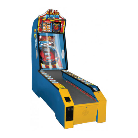
HOW TO PLAY Step right up and pick your game! Classic Roller or Ring of Fire, 1-4 players. Roll all nine balls into the targets, according to the directions displayed on the monitor. See frame-by-frame scores and compare with the other players! In Ring-of-Fire, aim for the lighted ring for Double Points! Grab your tickets and play again! -
Page 6: Specifications
GAME SPECIFICATIONS WEIGHT POWER REQUIREMENTS NET WEIGHT 450 LBS. INPUT VOLTAGE 100 to 120 220 to 240 RANGE SHIP WEIGHT 550 LBS. INPUT FREQUENCY 50 HZ 60 HZ DIMENSIONS RANGE WIDTH 30” MAX START UP OPERATING CURRENT CURRENT DEPTH 114” 2.6 AMPS @ 115 VAC 1.5 AMPS @ 115 VAC HEIGHT... -
Page 7: Dip Switch Settings
DIP SWITCH SETTINGS The dip switch bank is located on the mainboard, inside the front door of the game. *factory default settings are highlighted below THE DIPS MUST BE SET AS SHOWN FOR THE GAME TO FUNCTION PROPERLY SWITCH... -
Page 8: Quick Set Up Guide
QUICK SET UP GUIDE Place the target cabinet near its final location. Push the ramp cabinet to about a foot from the target cabinet, and plug in the six sets of from the front cables as shown. The phone cable linkage can be found in the cashbox of the game. - Page 9 QUICK SET UP GUIDE Drop the 9 balls (found in a box inside the target cabinet) into the playfield. Plug the power cable into the back of the target cabinet and into a standard 110V elec- trical outlet. Open the front doors of the ramp and switch the power strip to “on”.
-
Page 10: Main Menu Functions
MAIN MENU FUNCTIONS The menu access buttons are located inside the front door of the ramp. MENU/SELECT Press the button to enter the Main Menu. SCROLL Move through the menu with the button. MENU/SELECT Make your selection with the button. CLEAR CREDITS Press and hold the MENU/SELECT... -
Page 11: Game Setup Menu
GAME SETUP MENU Credits/ Game Ticket Pattern (see next page) Fixed Ticket DISABLED 1 TICKET 40 TICKETS Payout Attract 100 110 120 Volume Game 100 110 120 Volume... -
Page 12: Ticket Patterns
TICKET PATTERNS GAME SCORE (in thousands) TICKET PATTERN TICKETS 100 150 1000 100 1000 100 250 1000 100 1000 100 200 500 1000 100 1000 100 120 1000 100 200 500 1000 100 150 200 1000 100 200 240 2000 1000... -
Page 13: Diagnostics Menu
DIAGNOSTICS MENU This diagnostic mode will help in determining if all sensors and inputs are functioning correctly. Activating any input listed here should turn the display from OFF to ON. The game will automatically alternate lighting the targets in numerical order while diagnostic mode is on. -
Page 14: Troubleshooting Guide
TROUBLESHOOTING GUIDE Problem Probable Cause Remedy Unplugged. Check wall outlet to line filter in back of game. (A5FI9010) No power to the Connector loose Check connection between head game. between head and ramp and ramp. Power strip turned off, or Check rocker switch on power strip. - Page 15 TROUBLESHOOTING GUIDE Problem Probable Cause Remedy Ensure bill acceptor has 110 Acceptor should cycle stacker at game power up. Volts AC. If not, check cable connections to power strip. Caution – 110 Volts AC Note: Game will allow 12 Volt DBA to be installed.
- Page 16 TROUBLESHOOTING GUIDE PROBLEM PROBABLE CAUSE REMEDY Ticket tray empty due to faulty Fill ticket tray. Replace low ticket switch(AASW200). low ticket switch or broken/ Repair wiring. Clean ticket tray of dirt, loose tickets or loose wires. Switch stuck or debris. Bend switch wire to correct position under tickets. switch wire bent out of position.
- Page 17 TROUBLESHOOTING GUIDE Problem Probable Cause Remedy Ball release solenoid sticking. Check for free movement of assembly. Balls are not Check for 110 VAC pulse at solenoid. released. AC Driver Board defective. Check for green LED pulse on driver board If pulse ok: Replace fuse located in small box on AC driver board.
- Page 18 TROUBLESHOOTING GUIDE Problem Probable Cause Remedy Game starts with a score Opto is defective under score hole. Game scores already on display or scores Enter menu, go to Diagnostics Menu to check wrong. double points. sensors. Replace defective opto. (AACB2203) Main Board and wiring to coin switch OK.
- Page 19 TROUBLESHOOTING GUIDE Problem Probable Cause Remedy Small 12 Volt power connector unplugged on motherboard. Monitor VGA cable unplugged. Monitor says NO SIGNAL Large power connector unplugged on for 5 seconds Motherboard after power Faulty or loose RAM Then dark. Refer to Monitor/Motherboard Power Supply Diagnostics Section Monitor to check for f aulty power supply or motherboard.
- Page 20 DOLLAR BILL ACCEPTOR DIAGNOSTICS Note: There are many different models and brands of Bill Acceptors that are used on redemption games. Your Bill Acceptor may differ from the unit shown. First determine if Bill Acceptor has power: Turn game ON—The bill acceptor should make noise as stacker cycles and green lights on outside bezel should flash.
- Page 21 POWER SUPPLY DIAGNOSTICS 1.) Verify AC power to front of game. Check power strip in bottom front. Check for illuminated power switch. 2.) Verify AC power at power strip in top of game behind monitor Check for illuminated power switch. 3.) Check AC power connection to power supply.
-
Page 22: Updating Software
2) Locate USB software stick with the PC designator for Motherboard. 3) Remove existing USB stick and install the new USB stick with PC program. If you have any questions or need further assistance please contact Bay Tek Games. You may reach our Service Team at 920-822-3951 ext. 1102... -
Page 23: Wiring Diagrams
WIRING DIAGRAMS MAIN BOARD- AANEWGEN1-PJ... - Page 24 WIRING DIAGRAMS COUNTERS, RACK SENSOR, LEDS Front of Game To J22 on Main Board To J21 on Main Board AACE2035 Ticket Counter AACE2035 AACE2030 Game Push Counter Buttons Cable Rear of Ramp Piece Bottom of Head Piece AACE2041 AACE2036 AACE2036 AACB2203 Playfield LED’s: Playfield Diagram:...
- Page 25 WIRING DIAGRAMS AC & 12 VOLT POWER AAMB7 VGA Monitor Cable to VGA Monitor Cable to Motherboard Motherboard A5MO2200 Power Cord AACE2032 AACE2033 Playfield LED’s Power Cord to Power to Monitor Supply A5CORD5 A5CORD5 AACE2033 Playfield LED’s Power Supply A5PS1008 AACE2033 Playfield LED’s Top of Head Piece AACE2033 Playfield LED’s...
- Page 26 WIRING DIAGRAMS BALL RELEASE & TRACK SENSORS Ball Count Sensor AACB2203 Ball Release is controlled by signal to AC driver board. There is a 2 Amp fuse located in black box on board. Ball Count Sensor AACB2203 AACE2003 Connector is Left Disconnected Ball Release Signal...
- Page 27 WIRING DIAGRAMS COIN DOOR, TICKET DISPENSER, MENU BUTTONS, SPEAKERS To Ticket Dispense (A5TD1) 12 Volt Power Enable Signal Com Ground Notch Signal Low Ticket Switch Wired Normally Open AASW200 Speaker 1/4” Spacer A5SENY020 AACE2025 AACE8811 To Speaker AACE2006 From Green Audio Socket To J9 on on Motherboard To J5 on...
- Page 28 WIRING DIAGRAMS PLAYER GAME SELECT BUTTONS BLUE “CLASSIC ROLLER” A5CN1031 Adaptor to plug cable into Motherboard. From J22 Connector A5PB2002 (AACE2035) Push Buttons Cable From J24 Connector (AACE2003) Push Buttons Cable RED “RING OF FIRE” Button Wires AACE2030 Top of Head Piece A5CO2002 Coupler between AACE2011...
-
Page 29: Parts List
PARTS LIST PART NUMBER DESCRIPTION PART NUMBER DESCRIPTION A5BA2012 Natural Colored Balls (9 /Game) A5CEAU010 Cable, Audio, Stereo A5VF2002 Cash Box A5CN1031 Adapter from RJ45 to Motherboard A5CORD5 Computer Cord AACE2003 Ball Switch & Aux Drive Cable A5CO2002 Straight Coupler AACE2004 Coin Door Cable A5FI9010... -
Page 30: Parts Pictures
PARTS PICTURES A5CORD5 A5CO2002 A5FI9010 A5TD1 AABD5029 A5LK2000 A5LK5001 AACE8811 A5OU1000 A5PL9097 A5PB2001 A5VF2002 A5PS1008 AASW200 A5ME2018 A5ME2000-FF A5ME2001 -FF A5ME2002-FF A5ME2003-FF A5ME2004 -FF A5ME2005 A5ME2006 -FF A5ME2010-FF AACE2003 AACE2004 AACE2006 AACE2020 AACE2021 AACE2008 AACE2009 AACE2011 AACE2012 AACE2018... -
Page 31: Decal Identification
DECAL IDENTIFICATION A5DE2050_GFA_Marquee Front A5DE2051_GFA_Marquee Back A5DE2057_GFA_CabinetSideL A5DE2052_GFA_Playfield Backer A5DE2058_GFA_CabinetSideR (hidden in picture, right of cabinet) A5DE2053_GFA_Playfield A5DE2054_GFA_NumberSet A5DE2056_GFA_GutterCoverR A5DE2055_GFA_GutterCoverL A5DE2059_GFA_ControlPanelSet (around buttons) -
Page 32: Maintenance Log
MAINTENANCE LOG If repairs are necessary, it is good practice to keep a log of repairs done and parts ordered. The chart below will assist you in tracking your game’s maintenance. DATE MAINTENANCE PERFORMED PARTS ORDERED INITIALS... -
Page 33: Technical Support
Bay Tek games. Many of our games share the same main-board electronics. This means you can buy one set of spare electronics to support many of your Bay Tek games. Spare boards allow you to get your game up and running the quickest and provide you a valuable troubleshooting option. Call our... -
Page 34: Warranty
WARRANTY Bay Tek Games warrants to the original purchaser that all game components will be free of defects in workmanship and materials for a period of 6 months from the date of purchase. If you fill out the registration card in the cashbox of the game, Bay Tek will add another 3 months to your warranty, free of charge.
Need help?
Do you have a question about the GRAND FUN-ALLEY and is the answer not in the manual?
Questions and answers