Sign In
Upload
Manuals
Brands
Unipulse Manuals
Measuring Instruments
F325
Unipulse F325 Manuals
Manuals and User Guides for Unipulse F325. We have
1
Unipulse F325 manual available for free PDF download: Operation Manual
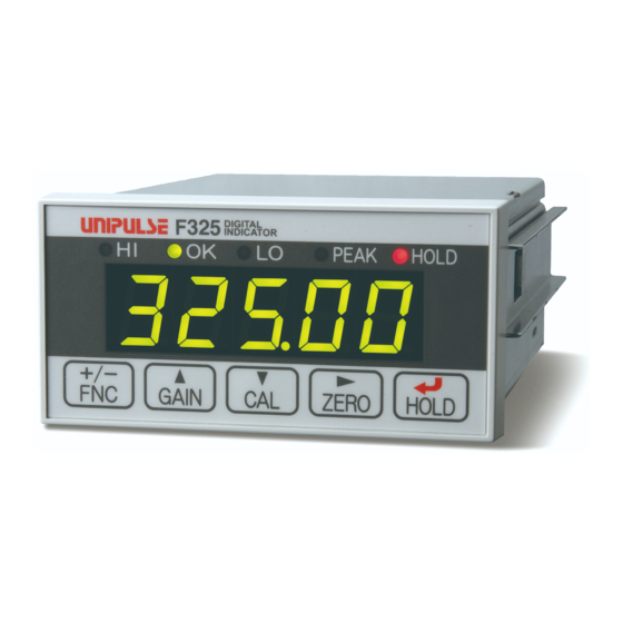
Unipulse F325 Operation Manual (160 pages)
digital indicator
Brand:
Unipulse
| Category:
Measuring Instruments
| Size: 3 MB
Table of Contents
Table of Contents
7
1 Outline
12
Package Contents
12
Connection with Other Devices
13
Name and Function of each Part
13
Front Panel
13
Rear Panel
16
Operating Procedures
19
2 Installation & Connection
20
Installation to Panel
21
Connection to the Signal I/O Terminal Block
22
Connection of Strain Gauge Type Sensors
23
Connection of Analog Monitor Output (VOL OUT)
24
Connection of Analog Monitor Output
24
Connection of RS-485 (RS-485 or SI/F Standard: Not Specified at the Time of Order)
25
Connection of
25
F Connection (RS-485 or SI/F Specified at the Time of Order: SIF)
26
External Output Connection
27
External Input Connection
28
Power Input Terminal Connection
30
AC Spec
30
DC Spec. (Specified at the Time of Order)
32
3 Setting Procedure
35
Setting Mode Configuration
35
Setting Items Display
37
Setting Procedure
39
4 Calibration
40
Calibration Method
40
Actual Load Calibration Procedures
41
Equivalent Input Calibration Procedures
41
Calibration LOCK Release
42
Calibration LOCK Setting Method
42
Excitation Voltage
42
Excitation Voltage Setting Method
42
Decimal Place Setting (Omit if There Is no Change.)
43
Decimal Place Setting Method
43
Min. Scale Division Setting (Omit if There Is no Change.)
43
Min. Scale Division Setting Method
43
Zero Calibration
44
Actual Load Calibration
44
4-10.Equivalent Input Calibration
45
Equivalent Input Calibration
45
4-11.Calibration LOCK
46
Calibration LOCK
46
Calibration LOCK Setting Method
46
5 Settings and Operations Related to Indicated Values
47
Display Frequency
47
Display Frequency Setting Method
47
Analog Filter
47
Analog Filter Setting Method
47
Moving Average Filter
48
Moving Average Filter Setting Method
48
Sampling Rate
48
Sampling Rate Setting Method
48
Digital Low-Pass Filter
49
Digital Low-Pass Filter Setting Method
49
Motion Detect
50
Motion Detect Setting Method
51
Zero Tracking
51
Zero Tracking Setting Method
51
Digital Zero
53
Digital Zero by Key Operation
53
Digital Zero by External Signal Input
53
Digital Offset
54
Digital Offset Setting Method
54
5-10.ZERO Key Valid/Invalid
54
ZERO Key Valid/Invalid Setting Method
54
6 Setting and Operation Related to Comparison
55
Output Selection
55
Output Selection Setting Method
55
HI Limit / lo Limit / HH Limit / LL Limit
56
HI Limit / lo Limit / HH Limit / LL Limit Setting Method
57
HI/LO Limit Comparison Mode
58
HI/LO Limit Comparison Mode Setting Method
59
Hysteresis
59
Hysteresis Setting Method
60
Alarm HI Limit, Alarm lo Limit
61
Alarm HI Limit and Alarm lo Limit Setting Method
61
Near Zero
62
Near Zero Setting Method
62
7 Settings and Operations Related to Hold
63
Hold Mode
63
Hold Mode Setting Method
63
Peak Hold (Maintaining a Maximum Point)
64
Sample Hold (Maintaining Arbitrary Points)
67
Peak Hold Selection
70
Peak Hold Selection Setting Method
70
Hold Fix Section
71
Hold Fix Section Setting Method
71
Renewal Timing of Hold Value
71
Renewal Timing of Hold Value Setting Method
71
Hold Detection Wait
72
Hold Detection Wait Setting Method
72
HOLD Key Valid/Invalid
73
HOLD Key Valid/Invalid Setting Method
73
8 Settings and Operations Related to SI/F Print
74
Automatic Printing Command
74
Automatic Printing Setting Method
75
Hold Value Printing
76
Hold Value Printing Setting Method
76
9 System Settings and Operations
77
Set Value LOCK
77
Set Value LOCK Setting Method
77
Password
78
Password Setting Method
78
Self-Check/Initialization
79
Self-Check
79
Initialization
80
I/O Input Check
81
I/O Output Check
81
BCD Input Check
81
BCD Output Check
82
RS-232C Check
83
Check
83
Interface
84
10 Analog Monitor Output (VOL OUT)
85
11 RUN Output
86
12 Interface
87
12-1.RS-485 Interface (RS-485 or Si/F Standard: Not Specified at the Time of Order)
87
Communication Specifications
87
Connection of RS-485
88
Setting Values Related to RS-485
89
UNI-Format Commands
91
Transmitting Format for Continuous Transmission/Printing
97
Modbus-RTU
98
12-2.SI/F (RS-485 or Si/Specified at the Time of Order: SIF)
118
Connection of SI/F
118
Regarding Indicated Values Transmitted by SI/F
118
13 Options
119
13-1.BCD Data Output
119
Setting Values Related to BCD Data Input
120
Sink Type (BCO Option)
121
Source Type (BSC Option)
124
13-2.D/A Converter
128
Voltage Output (DAV Option)
128
Current Output (DAI Option)
130
Setting Values Related to D/A Converter
132
13-3.RS-232C Interface
134
Communication Specifications
134
Cables
134
Setting Values Related to RS-232C
135
Communication Format for Commands
137
Setting Value Communication Format
140
Continuous Transmitting Format
143
14 Error Message Display
144
15 Specifications
145
Display Section
146
External I/O Signal
147
Interface
148
Options
149
General Performance
151
Dimensions
152
When BCO/BSC Option Is Selected
153
When DAV / DAI Option Is Selected
154
When RS-232C Option Is Selected
155
F325 Block Diagram
156
16 Setting Values List
157
Advertisement
Advertisement
Related Products
Unipulse F370
Unipulse F320
Unipulse F377A
Unipulse F701+
Unipulse FC400-DAC
Unipulse FS2000
Unipulse F340A
Unipulse f395
Unipulse F372A
Unipulse F371
Unipulse Categories
Measuring Instruments
Touch Panel
Controller
Monitor
Accessories
More Unipulse Manuals
Login
Sign In
OR
Sign in with Facebook
Sign in with Google
Upload manual
Upload from disk
Upload from URL