
Subscribe to Our Youtube Channel
Related Manuals for Weidmuller UR20-4COM-IO-LINK


Summary of Contents for Weidmuller UR20-4COM-IO-LINK
- Page 1 Remote-I/O-System u-remote UR20 Communication module UR20-4COM-IO-LINK Manual Letʼs connect.
-
Page 2: Table Of Contents
Reading and writing data objects on IO-Link devices 6.10 “IO_LINK_CALL” function block 6.11 I&M functions Manufacturer Weidmüller Interface GmbH & Co. KG Klingenbergstraße 26 D-32758 Detmold T +49 5231 14-0 +49 5231 14-292083 Document No. 2547720000 www.weidmueller.com Revision 03/September 2019 Manual Communication module UR20-4COM-IO-LINK 2547720000/03/09.2019... -
Page 3: About This Documentation
Notes with the signal word “Attention” warn you of hazards information and notes about the communication that may result in material damage. module UR20-4COM-IO-LINK. It supplements but does not replace the u-remote IP20 manual (document No. 1432790000). Text next to this arrow are notes that are... -
Page 4: Standard Data Structure
1334910000 UR20-FBC-EC, HW 02.xx.xx 01.11.00 1334910000 UR20-FBC-EC, HW 01.xx.xx 01.10.00 2476450000 UR20-FBC-MOD-TCP-V2 02.07.00 1334930000 UR20-FBC-MOD-TCP 02.07.00 1334920000 UR20-FBC-EIP, HW 02.xx.xx 02.08.00 1334920000 UR20-FBC-EIP, HW 01.xx.xx 01.08.00 1334900000 UR20-FBC-DN 01.07.00 1334890000 UR20-FBC-CAN 01.07.00 1334940000 UR20-FBC-PL 01.07.00 Manual Communication module UR20-4COM-IO-LINK 2547720000/03/09.2019... -
Page 5: Safety
Safety Open equipment This chapter includes general safety instructions for handling the communication module UR20-4COM-IO-LINK. Specific u-remote products are open equipment that may only be in- warning notices for specific tasks and situations are given at stalled and operated in lockable housings, cabinets or electri- the appropriate places in the documentation. -
Page 6: Intended Use
If u-remote products are used in potentially explosive atmos- pheres, the following notes are also applicable: The UR20-4COM-IO-LINK communication module is an I/O – Staff involved in assembly, installation and operation must module from the u-remote series. It is intended for use in a be qualified to perform safe work on electrical systems u-remote station. -
Page 7: Legal Notice
2 Safety | Legal notice Legal notice The communication module UR20-4COM-IO-LINK is CE- compliant in accordance with Directive 2014/30/EU (EMC Directive). It also meets the requirements of the ATEX Direc- tive 2014/34/EU. The results of the measurements according to CISPR 16-2- 3 should also be suitable to demonstrate the compliance of the u-remote devices to the limits for radiated emissions as defined by CFR 47 Part 15, Subpart B, §15.109, Class A... - Page 8 Manual Communication module UR20-4COM-IO-LINK 2547720000/03/09.2019...
-
Page 9: Io-Link Overview
You will find more information on IO-Link and An IO-Link device is connected with an IO-Link port of the IODDs at http://www.io-link.com. IO-Link master with 3-cable or 5-cable technology. 2547720000/03/09.2019 Manual Communication module UR20-4COM-IO-LINK... - Page 10 Manual Communication module UR20-4COM-IO-LINK 2547720000/03/09.2019...
-
Page 11: Module Description
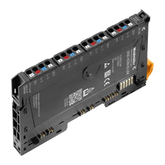
4 Module description Module description You can use the “u-remote IO-Link configurator” software to configure the IO-Link system for the UR20-4COM-IO-LINK. Digital communication module UR20-4COM-IO-LINK (order no. 1315740000) The digital communication module UR20-4COM-IO-LINK is an IO-Link master according to IO-Link specification V1.1.2. -
Page 12: Device Description
11 Channel status LED 12 Latching hook for latching onto module sides 13 DIN rail foot 14 Type plate I/O-Module components Base module Electronic unit Removal lever for electronic unit Connector frame Connector Plug-in unit Manual Communication module UR20-4COM-IO-LINK 2547720000/03/09.2019... -
Page 13: Connections
Connection Signal Function IO-Link communication GND IN 24 V DC IN Digital input (type 1) A description of how IO-Link devices for both port classes and standard field devices can be connected to the module is available in chapter 5. 2547720000/03/09.2019 Manual Communication module UR20-4COM-IO-LINK... -
Page 14: Block Diagram
IO-Link port as per the IO-Link specification. The following table shows the assignment of plug-in connectors and channels to IO-Link ports for the UR20-4COM-IO-LINK communication module. Plug-in connector IO-Link port Channel Manual Communication module UR20-4COM-IO-LINK 2547720000/03/09.2019... -
Page 15: Technical Data
1) If C/Q is used as digital input, the connected device shall only be supplied via the L+ and L- connections of the respective channel. 2) Higher altitudes are possible when particular deratings are considered. Please contact your responsible Weidmüller company as needed. 2547720000/03/09.2019 Manual Communication module UR20-4COM-IO-LINK... - Page 16 1) If C/Q is used as digital input, the connected device shall only be supplied via the L+ and L- connections of the respective channel. 2) Higher altitudes are possible when particular deratings are considered. Please contact your responsible Weidmüller company as needed. Manual Communication module UR20-4COM-IO-LINK 2547720000/03/09.2019...
-
Page 17: Editable Parameters
4 Module description | Editable parameters Editable parameters Overview of the editable parameter UR20-4COM-IO-LINK Channel Description Options Default 0 ... 3 Operating mode disabled (0) / DO (1) / DI (2) / IO-Link (3) disabled 0 ... 3 Port cycle Free running (0) / Fixed cycle (1) / Message sync (2) Free running 0 ... 3... - Page 18 IO-Link master is deleted. If the Data Storage function is enabled, do not connect any IO-Link devices with unknown parameters to avoid saving incorrect parameters. Reset IO-Link devices to factory settings before you connect them. Manual Communication module UR20-4COM-IO-LINK 2547720000/03/09.2019...
- Page 19 The cyclic output data of the IO-Link device connected occu- pies 0 … 32 bytes of the IO-Link master process output data. auto (default) The length of the cyclic output data is automatically set to match the IO-Link device connected. 2547720000/03/09.2019 Manual Communication module UR20-4COM-IO-LINK...
- Page 20 Manual Communication module UR20-4COM-IO-LINK 2547720000/03/09.2019...
-
Page 21: Assembly And Installation
▶ In addition, always refer to the complete doc- umentation in the u-remote IP20 manual. ▶ Carry out all work during the installation/removal and replacement of components as described in the u-remote manual. 2547720000/03/09.2019 Manual Communication module UR20-4COM-IO-LINK... -
Page 22: Connecting Standard Field Devices
▶ Connect the IO-Link device as shown in the figure. Connecting sensor to DI ▶ Connect the sensor as shown in the figure. Connect load to C/Q Connect load to C/Q ▶ Connect the load as shown in the figure. Manual Communication module UR20-4COM-IO-LINK 2547720000/03/09.2019... -
Page 23: Commissioning
The version number of an EDS file can be found from the file. wired. Open the file using a text editor. – The fieldbus coupler and UR20-4COM-IO-LINK module – Ethernet/IP: “Revision” entry in the “File” section must use the current firmware versions. -
Page 24: Procedure For Commissioning
This procedure ▶ Update the firmware of the fieldbus coupler and that of is suitable when you want to use the same configuration a the UR20-4COM-IO-LINK modules to the latest version. number of times. Configuring the IO-Link master ▶... -
Page 25: Commissioning With The Simatic Manager (Profinet)
IO-Link devices connected. ▶ When the installation is complete, click Close. ▶ In the device catalogue, select the UR20-4COM-IO-LINK ▶ Update the device catalogue via Extras / Update cata- module with a process data length greater than or equal logue. - Page 26 An IO-Link device is integrated using the suitable parameteri- zation of the associated IO-Link port. ▶ Double-click the module in the module list. The UR20-4COM-IO-LINK Properties window opens. ▶ Select the Parameters tab. ▶ Set the “Operating mode” parameter of the IO-Link port to the value “IO-Link”.
-
Page 27: Commissioning With The Tia Portal(Profinet)
IO-Link master, by adding the length of the input data and output data of the IO-Link devices connected. ▶ In the device catalogue, select the UR20-4COM-IO-LINK module with a process data length greater than or equal to the required length. - Page 28 ▶ Click the parameter that you would like to change and select the desired setting. ▶ Use this method to edit all of the parameters that you would like to change. All settings only take effect once they have been loaded into the component. Manual Communication module UR20-4COM-IO-LINK 2547720000/03/09.2019...
-
Page 29: Commissioning With Twincat (Ethercat)
▶ Click OK. ▶ Use this method to edit all of the parameters that you would like to change. All settings only take effect once they have been loaded into the component. IO-Link master in Solution Explorer 2547720000/03/09.2019 Manual Communication module UR20-4COM-IO-LINK... -
Page 30: Commissioning With Studio 5000(Ethernet/Ip)
▶ Scan the network. ▶ Right-click the fieldbus coupler. ▶ In the context menu, click Class Instance Editor. ▶ Read the warning message and confirm by clicking on Yes. The Class Instance Editor is opened. Manual Communication module UR20-4COM-IO-LINK 2547720000/03/09.2019... - Page 31 ▶ In the drop-down list Transmit data size, select Byte. ▶ Determine the required length of the input data of the UR20-4COM-IO-LINK module by adding the length of the input data of the connected IO-Link devices as well as 2 status bytes for the module.
- Page 32 Alternatively, you can parameterise IO-Link ports using acy- ance with the process data length of the fieldbus coupler. clic write accesses. ▶ Click OK. ▶ Download the changes to the controller. Setting the process data length of the coupler Manual Communication module UR20-4COM-IO-LINK 2547720000/03/09.2019...
-
Page 33: Commissioning With Automation Studio (Powerlink)
▶ Create a new project or open an existing project. ▶ Configure the control unit and the network as usual. ▶ Add the appropriate u-remote fieldbus coupler. ▶ Add the UR20-4COM-IO-LINK module from the hardware catalogue to the u-remote station. ▶ Connect the fieldbus coupler to the controller. - Page 34 ▶ Set the “Process data length output” parameter of the IO-Link port to the value “auto (default)”. ▶ Change the other parameters as required. All settings only take effect once they have been loaded into the component. Manual Communication module UR20-4COM-IO-LINK 2547720000/03/09.2019...
-
Page 35: Reading And Writing Data Objects On Io-Link Devices
– IO-Link Integration – Edition 2: Guideline for / without data PROFINET / Resource busy acyclic-read.res read.conf data / “resource busy“ / with data acyclic-read.req / without data data acyclic-read.res read_data.res / with data Reading a data object on an IO-Link device 2547720000/03/09.2019 Manual Communication module UR20-4COM-IO-LINK... - Page 36 IOL subindex IO-Link device data or port function 0x00 Read access: Data IOL data object 0 ... 232 Write access: – – Error incident: error code 1) Not for PROFIBUS and PROFINET 2) Not for PROFIBUS and PROFINET Manual Communication module UR20-4COM-IO-LINK 2547720000/03/09.2019...
- Page 37 Port 4: Length of process output data 0 x 03 Port 4: Pos OUT Port 4: Position process output data 0 x 09 1) Not for PROFIBUS and PROFINET 2) Not for PROFIBUS and PROFINET 2547720000/03/09.2019 Manual Communication module UR20-4COM-IO-LINK...
-
Page 38: 6.10 "Io_Link_Call" Function Block
Length of data to be written in bytes 2) Not for PROFIBUS and PROFINET Read access: not required Write access: 1 ... 232 ARRAY OF Read access: Target range for data RECORD_IOL_DATA BYTES Write access: Source range for data Manual Communication module UR20-4COM-IO-LINK 2547720000/03/09.2019... - Page 39 In the case of S7-300/400 CPUs, use the logical start address of the module inputs as ID. In the case of S7-1200/1500 CPUs, use the hard- ware address of the module as ID. 2547720000/03/09.2019 Manual Communication module UR20-4COM-IO-LINK...
-
Page 40: I&M Functions
REVISION_COUNTER Read Incremented for every static stored parameter change on IO-Link-Master (e.g. Device Name or IP-Address) PROFILE_ID Read 0x4E00 (IO-Link-Master) PROFILE_SPECIF- Read 0x0000 IC_TYPE IM_VERSION Read 0x0101 (I&M Version 1.1) IM_SUPPORTED Read 0x0001 (Profile specific) Manual Communication module UR20-4COM-IO-LINK 2547720000/03/09.2019... -
Page 41: Planning Io-Link Device Configurations
The licence conditions are displayed when the 12 Deactivating the IO-Link port program is started for the first time. 13 Activating an IO-Link port ▶ Read and confirm the licence conditions. 14 Displaying the context menu 2547720000/03/09.2019 Manual Communication module UR20-4COM-IO-LINK... - Page 42 What functions are displayed in the context menu depends on the current program context. The functions relate to the current displayed view in the program. Displaying the context menu ▶ Click ☰ to display the context menu. Manual Communication module UR20-4COM-IO-LINK 2547720000/03/09.2019...
- Page 43 An exported configuration only contains the IO- Link device parameters that you have activated. Therefore, only the activated parameters are over- written when you load the configuration to the u-remote station. 2547720000/03/09.2019 Manual Communication module UR20-4COM-IO-LINK...
-
Page 44: Editing Io-Link Device Configurations
▶ Navigate to the IO-Link port overview. ▶ Read the process data length of the current configuration. – PD IN: Length of the input data in bytes – PD OUT: Length of the output data in bytes Manual Communication module UR20-4COM-IO-LINK 2547720000/03/09.2019... -
Page 45: Editing Io-Link Device Configurations Online
▶ Repeat the procedure until all errors have been rectified. The online mode of the IO-Link Configurator is started. The fieldbus coupler with connected UR20-4COM-IO-LINK mod- ules is displayed in the device tree. ▶ Click in the device tree on the IO-Link master whose configuration you want to edit. - Page 46 ▶ For the IO-Link port to which the IO-Link device is con- nected, click Identify (magnifying class icon). If you want to update an individual parameter: ▶ Click the update icon next to the entry. Manual Communication module UR20-4COM-IO-LINK 2547720000/03/09.2019...
- Page 47 ▶ Edit the parameters of the IO-Link devices. ▶ Navigate to the IO-Link port overview of the IO-Link master. ▶ Open the context menu in the IO-Link port overview of the IO-Link master. ▶ Click Apply configuration. 2547720000/03/09.2019 Manual Communication module UR20-4COM-IO-LINK...
- Page 48 Manual Communication module UR20-4COM-IO-LINK 2547720000/03/09.2019...
-
Page 49: Process Data
Process data Process data mapping Example: Process data mapping (Configuration: UR20-4COM-IOL-16BYTE-INOUT) The process data length of the UR20-4COM-IO-LINK module is adjustable and can be adjusted to the respective IO-Link device configuration. The procedure for adjusting the pro- cess data length depends on which fieldbus coupler and which engineering tool you are using (see Chapter 6). -
Page 50: Process Input Data
8 Process data | Process input data Process input data Process output data Process data inputs UR20-4COM-IO-LINK Process data outputs UR20-4COM-IO-LINK Byte Description Byte Description IX0.0 DI 1 OX0.0 DO 1 IX0.1 DI 2 OX0.1 DO 2 IX0.2 DI 3 OX0.2 DO 3 IX0.3... -
Page 51: Fieldbus-Dependent Process Data Widths
Byte Byte Byte UR20-FBC-PB-DP Process data for IO-Link devices Fieldbus dependent data widths Input Output Input Output Byte Byte Byte Byte 1) incl. 2 Byte module process data 1) incl. 2 Byte module process data 2547720000/03/09.2019 Manual Communication module UR20-4COM-IO-LINK... - Page 52 Process data for IO-Link devices Fieldbus dependent data widths Input Output Input Output Byte Byte Byte Byte 0 ... 62 0 ... 62 2 ... 64 2 ... 64 1) incl. 2 Byte module process data 1) incl. 2 Byte module process data Manual Communication module UR20-4COM-IO-LINK 2547720000/03/09.2019...
- Page 53 Process data for IO-Link devices Fieldbus dependent data widths Input Output Input Output Byte Byte Byte Byte 0 ... 62 0 ... 62 2 ... 64 2 ... 64 1) incl. 2 Byte module process data 2547720000/03/09.2019 Manual Communication module UR20-4COM-IO-LINK...
- Page 54 Manual Communication module UR20-4COM-IO-LINK 2547720000/03/09.2019...
-
Page 55: Diagnostics And Troubleshooting
A DS parameter can‘t be accessed Error at channel 0 0xFF91 Request DS upload Error at channel 1 Error at channel 2 Channel error Error at channel 3 4 ... 7 Reserved 8 ... 10 8 ... 31 Reserved 2547720000/03/09.2019 Manual Communication module UR20-4COM-IO-LINK... -
Page 56: Led Indicators And Troubleshooting
– There is a new diagnostic message – Check the configuration Channel LED Yellow: – Status COM 1 ... COM 4 1.1 ... 4.1 – Red: – Fehler IO-Link port 1 ... IO-Link port 4 – Check the wiring 1.2 ...4.2 – Check the configuration Yellow: – Status DI 1 ... DI 4 1.4 ... 4.4 – Manual Communication module UR20-4COM-IO-LINK 2547720000/03/09.2019... -
Page 57: 10 Disassembly And Disposal
▶ Slide the module group to the right and remove it from the DIN rail. ▶ Repeat the above procedure for all remaining modules/ module groups. ▶ Please observe the instructions for proper disposal.. 2547720000/03/09.2019 Manual Communication module UR20-4COM-IO-LINK... - Page 58 Weidmüller – Your Partner in Industrial Connectivity As experienced experts we support our customers and partners around the world with products, solutions and services in the industrial environment of power, signal and data. We are at home in their industries and markets and know the technological challenges of tomorrow.
Need help?
Do you have a question about the UR20-4COM-IO-LINK and is the answer not in the manual?
Questions and answers