Table of Contents
Advertisement
Available languages
Available languages
Quick Links
INSTRUCTION
EN
RVAR5-24A
i
Read this instruction before installation
and wiring of the product
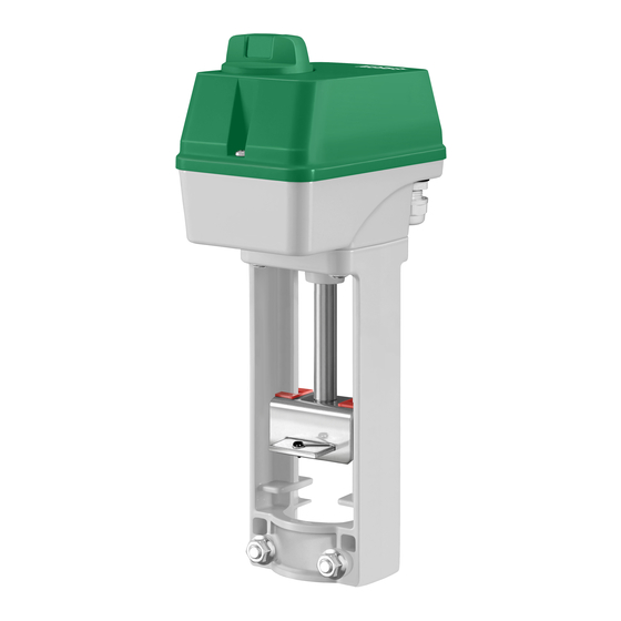
Valve actuator for 0(2)...10 V control
RVAR5-24A is a valve actuator designed for control of MMV and MMR
valves. The actuator has automatic self stroke adjustment and can be
operated manually.
Technical data
Supply voltage
24 V AC ±15 %, 50/60 Hz
or 24 V DC ±15 %
Control signal
0(2)...10 V DC
Max. power consumption
5.1 W / 13.9 VA
Stroke
10...30 mm
Stroke time
1.5 s/mm
Force
500 N
Ambient temperature
0...50°C
Storage temperature
-40...80°C
Ambient humidity
10...90 % RH
Dimensions (WxHxD)
150 x 295 x 85 mm
Protection class
IP54
If the valve stem adaptor and valve throat adaptor are not already mounted
on the valve, mount them. Pull the valve stem out as far as possible.
Mount the stem connector and fix it with the nut.
Remove the locking bolt (U-bolt) from the actuator yoke. Insert the valve
stem into the yoke and make sure that the stem adaptor engages the hole
in the angled iron of the actuator drive spindle.
The groove in the valve throat adaptor must be made to line up with the
U-bolt mounting holes on the actuator. If the spindle needs moving in or
out for this to happen, depress the central part of the manual button and
turn it clockwise for the actuator spindle to extend, and anti-clockwise for it
to retract (see Manual override). When the valve is in the correct position,
insert the U-bolt. Tighten the bolt nuts until the valve is firmly gripped.
Disassembly in reverse order.
Mounting positions
90º
Wiring
U
M
5
4
Measuring voltage
for position indication
U 0...10 V DC
Signal neutral
Y 0(2)...10 V DC
Control signal from
controller
Stroke and end position calibration
Stroke and end position calibration is not necessary due to a construction
utilizing end position stops. When the valve reaches the end position, a
force is generated. Once the force of the actuator reaches a predefined
level, the limit switch automatically halts the drive motor.
RVAR5-24A
Override
Activation of the override input will force the valve to the maximum
open position.
Manual override
90º
To manually set the valve position, first depress the central part of the
knob, until it clicks and remains depressed (1 in the figure). Then the
valve position can be changed manually by turning the knob (2 in the
figure). When the knob is turned clockwise, the drive rod is pushed
outwards and when the knob is turned anti-clockwise, the drive rod is
pulled inwards.
To return to normal operation, set the knob so that it is in line with the
text "Auto" on the cover. Then depress the outer parts of the knob (3
in the figure). The central depressed part will pop out, and the actua-
G0
G
Y
B
tor will return to normal operation.
6
3
2
1
Note: After any manual operation the actuator will always run through
a zero point calibration.
DIP switches
There are six DIP switches for setting different functions. Follow the
table below for setting the DIP switches.
Adjusted settings will be valid only after the next power-on.
SW1
24 V AC/DC
SW2
SW3
SW4
SW5
SW6
1 (On)
0 (Off)
Spindle down when the
Spindle up when the valve
valve is closed
is closed (FS=factory set-
ting)
LOG
LIN (FS)
Y = 2...10 V DC
Y = 0...10 V DC (FS)
Reverse operation
Direct operation (FS)
Y signal split in accordance
No split function (FS)
with the setting of SW6
5(6)...10 V = 0...100 %
0(2)...5(6) V = 0...100 %
(FS)
1
Advertisement
Table of Contents

Related Manuals for Regin RVAR5-24A


Summary of Contents for Regin RVAR5-24A
- Page 1 Note: After any manual operation the actuator will always run through RVAR5-24A is a valve actuator designed for control of MMV and MMR a zero point calibration. valves. The actuator has automatic self stroke adjustment and can be operated manually.
- Page 2 Tel: +46 31 720 02 00, Fax: +46 31 720 02 50 Off: Unchanged valve characteristics. The actuator moves linearly in www.regincontrols.com, info@regin.se relation to the control signal. RVAR5-24A är ett ventilställdon för styrning av MMV- och MMR- ventiler. Ställdonet har automatisk lyfthöjdsjustering och kan köras SW3 Control signal manuellt.
- Page 3 SW1 Ventilens arbetsriktning installationen felaktig eller så gick On: Ventilen är stängd när spindeln är i sitt nedre läge. ventilens slaglängd förlorad Off: Ventilen är stängd när spindeln är i sitt övre läge. Rött ljus som blinkar snabbt Manuellt överstyrningsläge RVAR5-24A...
- Page 4 AB Regin, Box 116, 428 22 Kållered, Sweden Tel: +46 31 720 02 00, Fax: +46 31 720 02 50 Anschluss www.regincontrols.com, info@regin.se RVAR5-24A ist ein Stellantrieb für die Ansteuerung von MMV- und MMR- Ventilen. Der Stellantrieb hat automatische Hubanpassung und Handbe- dienung. Technische Daten Versorgungsspannung 24 V AC ±15 %, 50/60 Hz...
- Page 5 (WE=Werkseinstellung) LIN (WE) Y = 2...10 V DC Y = 0...10 V DC (WE) Invertierte Stellrichtung Normale Stellrichtung (WE) Y-Signal-Splittung entspre- Keine Splittung (WE) chend Einstellung an SW6 5(6)...10 V = 0...100 % 0(2)...5(6) V = 0...100 % (WE) RVAR5-24A...
- Page 6 INSTRUCTION Positions de montage Commande manuelle RVAR5-24A Veuillez lire cette instruction avant de procéder à 90º 90º l'installation et au raccordement de l'appareil. Moteur de vanne pour contrôle 0(2)...10 V RVA5-24A est un actionneur pour les vannes MMV et MMR.
- Page 7 Contact Pour cela, il faut brancher une résistance de 500 Ω entre Regin France, 32 rue Delizy, 93500 Pantin l’entrée du signal de commande (borne 3) et le neutre (borne 2) Tél. : +33 (0)1 41 71 00 34, Fax : +33 (0)1 41 71 46 46 et régler SW3 sur On (2...10 V DC).
Need help?
Do you have a question about the RVAR5-24A and is the answer not in the manual?
Questions and answers