
Related Manuals for Atmel AVR Butterfly


Summary of Contents for Atmel AVR Butterfly
- Page 1 AVR Butterfly Evaluation Kit ..................... User Guide...
-
Page 3: Table Of Contents
Table of Contents Section 1 Introduction ................... 1-1 Resources Available on the AVR Butterfly Kit...........1-2 Section 2 How to Operate the Preprogrammed Application ......... 2-3 Included Firmware..................2-3 Joystick Input ....................2-4 Menu System ....................2-5 Bootloader....................2-7 Section 3 Using the AVR Butterfly ..............3-11 Connectors....................3-11... - Page 4 AVR Butterfly User Guide 4271B–AVR–11/03...
-
Page 5: Introduction
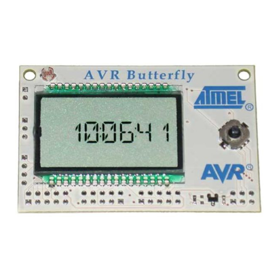
Section 1 Introduction The AVR Butterfly evaluation kit is designed to demonstrate the benefits and key fea- tures of the AVR microcontrollers. It is a stand alone microprocessor module that can be used in numerous applications: The AVR architecture in general and the ATmega169 in particular... -
Page 6: Resources Available On The Avr Butterfly Kit
Supported by AVR Studio 4. Pre-programmed with a demonstration application, including bootloader No external hardware is required to reprogram the AVR Butterfly The ATmega169 in the kit controls the external peripherals, and can also be used to do voltage readings from 0 to 5 volts. The kit can be reprogrammed a number of different ways including serial programming through the JTAG port. -
Page 7: How To Operate The Preprogrammed Application
Section 2 How to Operate the Pre-programmed Application The AVR Butterfly comes with a preprogrammed application. This section will go through the basics of this application. The firmware can be downloaded from the AVR Butterfly web-site, http://www.atmel.com/products/AVR/butterfly. Included These modules are preprogrammed with the AVR Butterfly:... -
Page 8: Joystick Input
Joystick Input To operate the AVR Butterfly a joystick is used as user input. It operates in five direc- tions, including center-push, see Figure 2-1. Figure 2-1. Joystick Input Using the joystick one can move around in the menu shown in Figure 2-2, and edit val- ues, entering name, etc. -
Page 9: Menu System
2.2.2 Entering Your Name 1. Connect a serial cable from the PC to the AVR Butterfly as described in Section Using a Terminal: 3.7 “Connect to PC”, Open a terminal on your PC (e.g. HyperTerminal) and con- figure the terminal to 19200 Baudrate, 8 Databits, none Parity and one stop bit. - Page 10 Figure 2-2. Application Menu AVR Butterfly User Guide 4271B–AVR–11/03...
-
Page 11: Bootloader
Figure 2-2 shows the menu system of the application that comes with the AVR Butterfly. The column to the left displays the main menu: “AVR Butterfly”, “Time”, “Music” etc… To shift between the alternatives in the menu, press the joystick UP or DOWN. To enter a sub-menu, press the joystick to the RIGHT. - Page 12 Extended Fuse Byte (0xFF) – None Fuse High Byte (0x98) – JTAGEN (JTAG Interface Enabled) – SPIEN (Serial Programming Enable) – BOOTSZ1 (1024 words Boot Size) – BOOTSZ0 – BOOTRST (Boot Reset vector Enabled) AVR Butterfly User Guide 4271B–AVR–11/03...
- Page 13 Lock Bit Byte (0xEF) – BLB11 (SPM is not allowed to write to the Boot Loader section) Note: For all fuses and lock bits, “1” means unprogrammed and “0” means pro- grammed.Using the AVR Butterfly AVR Butterfly User Guide 4271B–AVR–11/03...
- Page 14 AVR Butterfly User Guide 4271B–AVR–11/03...
-
Page 15: Using The Avr Butterfly
Section 3 Using the AVR Butterfly This section describes in detail how to use the AVR Butterfly evaluation kit. Connectors Some of the I/O-pins on the ATmega169 are available on the connectors of the AVR Butterfly. These connectors are for communication, programming and input to the ADC of the ATmega169. - Page 16 ISP-header, one can make contact just by pressing the header to the footprint. Make sure that pin 1 on the STK500 match with pin 1 on the AVR Butterfly. See Figure 3-3 for the pinout of the ISP Connector.
- Page 17 Figure 3-5. Reset, BSEL2 and XTAL1 cables Connect PROG DATA and PROG CTRL from the STK500 to respectively PORTB and PORTD on the AVR Butterfly. Make sure that pin 1 on the STK500 connects to pin 1 on the AVR Butterfly.
- Page 18 When the AVR Butterfly is configured in High-voltage Parallel Programming mode, the JTAG interface will not work, neither will the external crystal, causing the pre-programmed application that comes with the AVR Butterfly to not oper- ate correctly. AVR Butterfly User Guide...
-
Page 19: Jtag
Guide for information on how to use the STK500 front-end software in High-volt- age Programming mode. JTAG Figure 3-8 shows how to connect the JTAG ICE probe to the AVR Butterfly. Figure 3-8. JTAG connector Note: The JTAG connector must be mounted on the back-side of the AVR Butterfly. -
Page 20: Lcd Display
ADC[4:7]. See the ATmega169 datasheet for more information, available from www.atmel.com LCD Display The LCD display on the AVR Butterfly is the same as used on the STK502 available from Atmel. The connections between the ATmega169 and the LCD are also the same. See the STK502 User Guide at www.atmel.com... -
Page 21: Sensors
In addition is has a voltage-divider that is used to measure volt- ages from 0 to 5V. 3.6.1 Temperature Sensor The temperature sensor can be found at the back side of the AVR Butterfly. See Figure 3-12. AVR Butterfly User Guide 4271B–AVR–11/03... - Page 22 - - - - - - - - - - - - - - - - - - - - - ⎠ The AVR Butterfly is capable of measuring the temperature from –10ºC/+14ºF to +60ºC/140ºC with an accuracy of ±1ºC.
-
Page 23: Connect To Pc
3.6.2 Light Sensor The light sensor is located at the front of the AVR Butterfly, over the LCD. See Figure 3-15. Figure 3-15. Light Sensor An LDR (Light Dependent Resistor) is used to measure the light. An LDR is character- ised by the fact that when the light decreases the resistance goes up. -
Page 24: Usi
Pin 5 Figure 3-17. UART Connector The AVR Butterfly has connections for the USI-interface. Figure 3-18 shows the pin-out for the USI. Through the USI interface other modules can be connected, and the AVR Butterfly can serve as a top-module card. -
Page 25: External Dataflash
Pin 3 (DO) Pin 4 (GND) External An external dataflash is provided with the AVR Butterfly. This is the 4-megabit serial DataFlash from Atmel, type AT45DB041B. More information about the DataFlash can DataFlash be found in the datasheet available at the Atmel web site: http://www.atmel.com/products/DataFlash/... -
Page 26: Piezo Element
3.10 Piezo element A piezo element is used to be able to play sounds on the AVR Butterfly. The piezo is connected to PORTB5 on the ATmega169. And using the PWM, one can get the differ- ent frequencies required to play tunes. -
Page 27: Troubleshooting Guide
The update frequency is not correct. with the clock-source. Some segments on the LCD seems to Your fingers are touching the LCD pins or Hold the AVR Butterfly on the edge of the disappear PORTD PCB, without touching the LCD pins... - Page 28 AVR Butterfly User Guide 4271B–AVR–11/03...
-
Page 29: Technical Specifications
Section 5 Technical Specifications System Unit Physical Dimension ………………………………........…45 x 67 x 14 mm Weight...………………………………………………………………......28 g Operation Conditions Temperature…………………………………………………......…...0ºC - 50ºC If using external power……………………………………......……3,1V - 4,5V Temperature measurement accuracy……………………………….......…..±1ºC Voltage reading accuracy…………………………………………......….±0,1V AVR Butterfly User Guide 4271B–AVR–11/03... - Page 30 AVR Butterfly User Guide 4271B–AVR–11/03...
-
Page 31: Technical Support
Section 6 Technical Support For Technical support, please contact avr@atmel.com. When requesting technical sup- port, please include the following information: Which target AVR device is used (complete part number) Target voltage and speed Clock source and fuse setting of the AVR... - Page 32 AVR Butterfly User Guide 4271B–AVR–11/03...
- Page 33 Section 7 Schematics On the following pages the complete schematics and assembly drawing of the AVR But- terfly revision A are shown. AVR Butterfly User Guide 4271B–AVR–11/03...
- Page 34 Figure 7-1. Schematics, 1 of 4 AVR Butterfly User Guide 4271B–AVR–11/03...
- Page 35 Figure 7-2. Schematics, 2 of 4 AVR Butterfly User Guide 4271B–AVR–11/03...
- Page 36 Figure 7-3. Schematics, 3 of 4 AVR Butterfly User Guide 4271B–AVR–11/03...
- Page 37 Figure 7-4. Schematics, 4 of 4 AVR Butterfly User Guide 4271B–AVR–11/03...
- Page 38 Figure 7-5. Assembly Drawing, Top Side Figure 7-6. Assembly Drawing, Back Side AVR Butterfly User Guide 4271B–AVR–11/03...
-
Page 39: Bill Of Materials
BAT74 D300 PHILIPS BC847B Q200 PHILIPS NOT MOUNTED BC847BPN Q300 PHILIPS BLM-21A102S L100 BZX399-C1V8 D200 PHILIPS CR-2450 BT400 MAXELL H4042-DL U200 IQD32.768KHZ XC201 32,768kHz IQD Crystals ISP_CONNECTOR J403 SCOTT ELECT. NOT MOUNTED KEY-3008-TR J404 KEYSTONE AVR Butterfly User Guide 4271B–AVR–11/03... - Page 40 PH_2,54_3 X 1 J406 SCOTT ELECT. NOT MOUNTED PH_2,54_4 X 1 J405 SCOTT ELECT. NOT MOUNTED PH_2,54_5 X 2 J400 J401 SCOTT ELECT. NOT MOUNTED J402 SKRHABE010 SW200 ALPS KMT-1603 XC200 KINGSTATE VC080514A300 R300 R301 U562246 M500 AVR Butterfly User Guide 4271B–AVR–11/03...
- Page 41 No licenses to patents or other intellectual property of Atmel are granted by the Company in connection with the sale of Atmel products, expressly or by implication. Atmel’s products are not authorized for use as critical components in life support devices or systems.
Need help?
Do you have a question about the AVR Butterfly and is the answer not in the manual?
Questions and answers